Table des Matières
Publicité
Les langues disponibles
Les langues disponibles
Liens rapides
VENTILCONVETTORE PER INSTALLAZIONE CANALIZZATA, ORIZZONTALE E
FAN COIL FOR HORIZONTAL AND VERTICAL DUCTED INSTALLATION
VENTILO-CONVECTEUR POUR INSTALLATION CANALISÉE, HORIZONTALE
GEBLÄSEKONVEKTOR FÜR KANAL-, HORIZONTAL- UND VERTIKALEINBAU
FAN COIL PARA INSTALACIÓN CANALIZADA, HORIZONTAL Y VERTICAL -
VERTICALE - Manuale installazione
- Installation Manual
ET VERTICALE - Manuel d'installation
- Installationsanleitung
Manual de instalación
VES030
VES040
IT
GB
pag.6 pag.16 pag.26 pag.36 pag.46
VES130
VES140
FR
DE
ES
VES
VES230
VES330
VES240
VES340
IVES0LJ 1712 - 5799560_01
Publicité
Chapitres
Table des Matières

Manuels Connexes pour AERMEC VMF VES Série


Sommaire des Matières pour AERMEC VMF VES Série
- Page 1 VENTILCONVETTORE PER INSTALLAZIONE CANALIZZATA, ORIZZONTALE E VERTICALE - Manuale installazione FAN COIL FOR HORIZONTAL AND VERTICAL DUCTED INSTALLATION - Installation Manual VENTILO-CONVECTEUR POUR INSTALLATION CANALISÉE, HORIZONTALE ET VERTICALE - Manuel d’installation GEBLÄSEKONVEKTOR FÜR KANAL-, HORIZONTAL- UND VERTIKALEINBAU - Installationsanleitung FAN COIL PARA INSTALACIÓN CANALIZADA, HORIZONTAL Y VERTICAL - Manual de instalación VES030 VES130...
- Page 3 INDICE OSSERVAZIONI REMARKS REMARQUES HINWISE OBSERVACIONES DICHIARAZIONE DI CONFORMITÀ DECLARATION OF CONFORMITY DÉCLARATION DE CONFORMITÉ KONFORMITÄTSERKLÄRUNG DECLARACIÓN DE CONFORMIDAD TRASPORTO • SIMBOLI DI SICUREZZA CARRIAGE • SAFETY SYMBOL TRANSPORT • SIMBOLESES DE SECURITE TRANSPORT • SICHERHEITSSYMBOLE TRANSPORTE • SÍMBOLOS DE SEGURIDAD ITALIANO ENGLISH FRANÇAIS...
-
Page 4: Remarques
Nel quadro di una politica di miglioramento con- no 10 anni per eventuali riferimenti futuri. La garanzia dell'apparecchio non copre in ogni tinuo del prodotto, AERMEC S.p.A. si riserva la Leggere attentamente e completamente tutte le caso i costi dovuti ad autoscale, ponteggi o altri facoltà... - Page 5 TRASPORTO • TRANSPORT • TRANSPORT • TRANSPORT • TRANSPORTE N O N b a g n a r e . KEEP DRY. Keep out NE PAS mouiller. NICHT nass machen. NO mojar. Conservar Vor Regen geschützt Tenere al riparo dalla of the rain Tenir à...
-
Page 6: Table Des Matières
Realizzato con materiali di qualità superiore, nel rigoroso rispetto delle normative di sicurezza, VES è di facile utilizzo e vi accompagnerà a lungo nell'uso. La serie di ventilconvettori VES è progettata per essere integrata nel sistema VMF. VMF (Variable Multi Flow) è il sistema in grado di gestire in modo intelligente un impianto idronico completo, composto quindi da un chiller/pompa di calore, una caldaia, una rete di ventilconvettori (plurivelocità... -
Page 7: Informazioni Importanti • Manutenzione • Imballo • Uso
INFORMAZIONI IMPORTANTI E MANUTENZIONE ATTENZIONE: il ventilconvettore è ventilconvettore, ad ogni intervento di Durante il funzionamento si potrebbero collegato alla rete elettrica ed al manutenzione; ogni anomalia dovrà avvertire rumori e scricchiolii interni circuito idraulico, un intervento da essere comunicata al Servizio Assistenza. all'apparecchio dovuti alle diverse parte di personale non provvisto di dilatazioni termiche degli elementi... -
Page 8: Descrizione Dell'unità
DESCRIZIONE DELL’UNITÀ SCOPO DEI VENTILCONVETTORI VES I ventilconvettori VES, concepiti per adattarsi a qualsiasi esigenza negli impianti di tipo canalizzato, sono apparecchi non accessibili al pubblico. In particolare la possibilità di essere integrato nel sistema VMF permette il controllo dal singolo ventilconvettore con accessori fino alla gestione del VES inserito in reti complesse di ventilconvettori e dei loro accessori. -
Page 9: Esempi Di Impianto • Componenti Principali
ESEMPI DI IMPIANTO Legenda: Sonda temperatura acqua Sonda temperatura ambiente VC/F Valvola (Riscaldamento / Raffrescamento) Batteria (Riscaldamento / Raffrescamento) Valvola (Riscaldamento) Batteria (Riscaldamento) Impianto 2 tubi con sonda acqua Impianto 2 tubi senza sonda acqua VC/F VC/F VC/F VC/F Impianto 4 tubi con sonda acqua Impianto 4 tubi senza sonda acqua VC/F VC/F... -
Page 10: Ambiente Di Funzionamento
AMBIENTE DI FUNZIONAMENTO AVVERTENZE PER LA QUALITÀ DELL’ACQUA CIRCOLANTE NELLE BATTERIE Le unità sono state progettate per installazione in ambienti chiusi in condizioni di atmosfera ‘urbana’ non marina ed avente Si consiglia di fare eseguire un’analisi dell’acqua circolante nella caratteristiche di non corrosività e di non polverosità. Per nessun batteria focalizzata sulla ricerca dell’eventuale presenza di motivo devono esser superate le seguenti concentrazioni di batteri (rilevamento dei ferrobatteri e dei microrganismi che... -
Page 11: Limiti Di Funzionamento
LIMITI DI FUNZIONAMENTO Massima temperatura ingresso acqua °C Massima temperatura ingresso acqua consigliata °C Massima pressione d’esercizio (800000 Pa) Minima portata d'acqua (Batteria principale) Massima portata d'acqua (Batteria principale) 1500 1500 1500 1500 1500 1500 3000 4000 Minima portata d'acqua (Batteria Solo Riscaldamento) Massima portata d'acqua (Batteria Solo Riscaldamento) 1000 Limiti di temperatura ambiente (Ta) -
Page 12: Informazioni Per L'installazione • Installazione Dell'unità
INFORMAZIONI PER L'INSTALLAZIONE AT TENZIONE: prima di effettuare esigenze specifiche. con i collegamenti alle velocità standard. qualsiasi intervento, assicurarsi che E’ necessario che le condutture dell’acqua, Consultare lo schema elettrico prima di l’alimentazione elettrica sia disinserita. dello scarico condensa e il circuito modificare i collegamenti sul motore. -
Page 13: Collegamenti Idraulici • Collegamenti Scarico Condensa
INSTALLAZIONE DELLA FLANGIA DI MANDATA DELL'ARIA In caso di utilizzo della flangia di raccordo, • Montare per primo i due traversi laterali • Appoggiare i due traversi alla macchina e fornita a corredo della macchina, utilizzando 4 delle viti presenti nel attraverso le restanti 4 viti fissare i traversi a procedere come segue: sacchetto a corredo avvitandole ai 4 fori... -
Page 14: Collegamenti Elettrici
COLLEGAMENTI ELETTRICI L’ u n i t à d e v e e s s e r e c o l l e g a t a ATTENZIONE: Verificare che il pannello C A R AT T E R I S T I C H E D E I C AV I D I direttamente ad un attacco elettrico COLLEGAMENTO comandi sopporti il carico del motore... -
Page 15: Rotazione Della Batteria
VES 3 Velocità - Speed - Vitesse- Geschwindigkeit-Velocidad Collegamento Motore - Connection to Motor - Connexion à moteur- Verbindung zum Motor - Conexión a Motor STANDARD High High High High High ROTAZIONE DELLA BATTERIA Se per motivi di allacciamenti idraulici, si doves- SCHEMI DI ROTAZIONE DELLA BATTERIA se ruotare la batteria, dopo aver tolto il mobile VES030... - Page 16 Manufactured with superior quality materials, in strict compliance with safety standards, the VES is easy and durable in use. The VES fan coil series is designed to be integrated into the VMF system. VMF (Variable Multi Flow) is the system capable of controlling in an intelligent way a complete hydronic installation composed of a chiller/heat pump, a boiler, a network of fan coil units (multi-speed or continuous speed modulation) divided into zones (up to 64), the circulating pumps (up to 12) and the heat recovery units with air quality sensors (up to 3), optimising...
-
Page 17: Ordinary Maintenance
IMPORTANT INFORMATION AND MAINTENANCE WARNING: The fan coil unit is efficiency. and creaks inside the unit, due to connected to the power supply Visual inspection of the state of the the thermal expansion of the various network and the hydraulic circuit. fan coil unit for every maintenance components (plastic and metallic), but Any intervention by personnel not... -
Page 18: Horizontal Installation
UNIT DESCRIPTION SCOPE OF THE VES FAN COIL UNITS The fan VES, designed to fit any type of plants channeled devices are not accessible to the public. The possibility of integration into the VMF system allows the control from each fan coil unit with accessories up to the management of the VES inserted into a network of fan coil units and their accessories. -
Page 19: System Examples • Main Components
SYSTEM EXAMPLES Legend: Water temperature sensor Ambient temperature sensor VC/F Valve (Heat / Cool) Coil (Heat / Cool) Valve (Heat) Coil (Heat) 2 pipe system with water sensor 2 pipe system without water sensor VC/F VC/F VC/F VC/F 4 pipe system with water sensor 4 pipe system without water sensor VC/F VC/F... -
Page 20: Component Description
OPERATING ENVIRONMENT WARNINGS FOR THE QUALITY OF THE WATER CIRCULATING IN THE COILS The units are designed for installation in closed environments in conditions of ‘urban’, non-marine atmosphere with non-corrosive and non-dusty characteristics. It is recommended to perform an analysis of the water circulating in the coil focusing Under no circumstances the following concentrations of pollutants in the air, in on the research of the possible presence of bacteria (detection of iron bacteria and which the unit must operate, shall be exceeded:... -
Page 21: Operating Limits
OPERATING LIMITS Maximum water inlet temperature °C Maximum recommended water inlet temperature °C Maximum operating pressure (800 kPa) Minimum water flow rate (Main coil) Maximum water flow rate (Main coil) 1500 1500 1500 1500 1500 1500 3000 4000 Minimum water flow rate (Heating only coil) Maximum water flow rate (Heating only coil) 1000 Ambient temperature limits (Ta) -
Page 22: Installation Of The Unit
INSTALLATION INFORMATION WARNING: Disconnect the power The water piping, condensate discharge Refer to the wiring diagram before supply before carrying out any and electrical wiring must be installed modifying the motor connections. intervention. beforehand. If the valve is installed the minimum The fan coil unit must be installed in such temperature water sensor can be WA R N I N G : P r o v i d e a p p r o p r i a t e... -
Page 23: Hydraulic Connections • Condensate Discharge Connection
HYDRAULIC CONNECTIONS - Carry out the hydraulic connections. WARNING: Always use a spanner with counter-spanner to connect the piping. The positions, type and diameters of the hydraulic connections are shown in the dimensional data. It is recommended to properly insulate the water piping to avoid condensate drips during cooling operation. -
Page 24: Electrical Connections
ELECTRICAL CONNECTIONS The unit must be connected directly insulation rating enclosed inside a tube otherwise add the interface accessory t o a n e l e c t r i c a l o u t l e t o r a n or conduit. -
Page 25: Rotation Of The Coil
VES 3 Velocità - Speed - Vitesse- Geschwindigkeit-Velocidad Collegamento Motore - Connection to Motor - Connexion à moteur- Verbindung zum Motor - Conexión a Motor STANDARD High High High High High ROTATING THE COIL If the hydraulic connections require the COIL ROTATION DRAWING rotation of the coil, then after removal VES030... - Page 26 Réalisé avec des matériaux de qualité supérieure, dans le plus grand respect des règles de sécurité, le modèle VES est facile à utiliser et il a été conçu pour durer longtemps. La série de ventilo-convecteurs VES est conçue pour être intégrée dans le système VMF. VMF (Variable Multi Flow) est le système en mesure de gérer de manière intelligente une installation hydronique complète, il est composé...
-
Page 27: Dépose Et Remontage Du Filtre Àair
INFORMATIONS IMPORTANTES ET ENTRETIEN ATTENTION : le ventilo-convecteur est sur les surfaces externes ou internes du ANOMALIES DE FONCTIONNEMENT branché au réseau électrique et au cir- ventilo-convecteur (on risque des courts- En cas de mauvais fonctionnement, cou- cuit hydraulique: l’intervention de per- per le courant, puis le rétablir et redé- circuits). -
Page 28: Objet Des Ventilo-Convecteurs Ves
DESCRIPTION OBJET DES VENTILO-CONVECTEURS VES Le ventilateur VES, conçu pour adapter à tout type de plantes dispositifs canalisés ne sont pas accessibles au public. En particulier, la possibilité d'être intégré dans le système VMF permet le contrôle du ventilo-convecteur individuel avec accessoires à la gestion de l'unité... -
Page 29: Exemples D'installation • Composants Principaux
EXEMPLES D'INSTALLATION Legenda: Sonde de température de l'eau Sonde de température ambiante VC/F Vanne (chauffage/refroidissement) Batterie (chauffage/refroidissement) Vanne (chauffage) Batterie (chauffage) Installation à 2 tubes avec sonde d'eau Installation à 2 tubes sans sonde d'e VC/F VC/F VC/F VC/F Installation à 4 tubes avec sonde d'eau Installation à... -
Page 30: Description Des Composants
ENVIRONNEMENT DE FONCTIONNEMENT AVERTISSEMENTS POUR LA QUALITÉ DE L’EAU QUI CIRCULE DANS LES BATTERIES Les unités ont été conçues pour être installées dans des locaux fermés possédant les conditions d’une atmosphère « urbaine » et non pas Il est recommandé de faire réaliser une analyse de l’eau qui circule littorale, sans être corrosifs ni poussiéreux. -
Page 31: Limites De Fonctionnement
LIMITES DE FONCTIONNEMENT Température maximale de l'eau à l'entrée °C Température maximale conseillée de l'eau à l'entrée °C Pression de service maximale (800 kPa) Débit d'eau minimal (Batterie principale) Débit d'eau maximal (batterie principale) 1500 1500 1500 1500 1500 1500 3000 4000 Débit d'eau minimal (batterie chauffage seul) -
Page 32: Informations Pour L'installation • Installation De L'unité
INFORMATIONS POUR L'INSTALLATION ATTENTION : avant d'effectuer une quel- circuit électrique aient déjà été prévues. avant de modifier les connexions du conque intervention, vérifier si l'alimen- Le ventilo-convecteur doit être installé de moteur. tation électrique est débranchée. manière à ce que l'air soit distribué dans Si la vanne à... -
Page 33: Raccordements Hydrauliques • Raccordements Pour Évacuation Des Condensats
RACCORDEMENTS HYDRAULIQUES - Effectuer les raccordements hydrau- liques. ATTENTION : Utiliser toujours une clé et une contre-clé pour fixer les tuyaux. La position, le type et le diamètre des rac- cordements hydrauliques sont reportés dans les données dimensionnelles. Il est conseillé d'isoler de manière appro- priée les tuyaux de l'eau et/ou d'instal- ler le bac auxiliaire de récupération des condensats prévu, disponible comme... -
Page 34: Raccordements Électriques
RACCORDEMENTS ÉLECTRIQUES L'unité doit être branchée directement exigent l'association avec des compo- à un branchement électrique ou à un CARACTÉRISTIQUES DES CÂBLES sants fournis comme accessoires, véri- circuit indépendant. DE CONNEXION fier leur disponibilité. ATTENTION : il est obligatoire de bran- Utiliser des câbles de type H05V-K ou bien ATTENTION : Vérifier si le panneau de com- cher les câbles d'alimentation de... -
Page 35: Rotation De La Batterie
VES 3 Velocità - Speed - Vitesse- Geschwindigkeit-Velocidad Collegamento Motore - Connection to Motor - Connexion à moteur- Verbindung zum Motor - Conexión a Motor STANDARD High High High High High ROTATION DE LA BATTERIE Si à cause des raccords hydrauliques il faut SCHÉMA DE ROTATION DE LA BATTERIE tourner la batterie, effectuer les opérations VES030... - Page 36 Das Modell "VES", das aus erstklassigen Materialien und unter strenger Beachtung der Sicherheitsbestimmungen hergestellt wurde, ist benutzerfreundlich und zeichnet sich durch eine lange Lebensdauer aus. Die VES-Baureihe der Gebläsekonvektoren wurde für den Einbau in das VMF-System konzipiert. VMF (Variable Multi Flow) ist ein intelligentes Steuerungssystem für eine komplette hydronische Anlage und besteht aus einem Kaltwassersatz/Wärmepumpe, einem Heizkessel, einem Gebläsekonvektorennetz (mit mehrstufiger Drehzahl oder permanenter Drehzahlmodulation), das in (bis zu 64) Bereiche unterteilt ist, (bis zu 12) Umlaufpumpen und...
- Page 37 WICHTIGE INFORMATIONEN UND WARTUNG Lösemittel für die Reinigung des Geblä- und Metall) beruhen. Dies ist jedoch kein ACHTUNG: Der Gebläsekonvektor sekonvektors verwenden. Kein Wasser Anzeichen für eine Störung und bewirkt ist mit dem Stromnetz und dem Was- auf die Außen- oder Innenflächen des keine Schäden am Gerät, wenn die serkreis verbunden.
-
Page 38: Beschreibung Der Einheit • Erhältliche Größen
BESCHREIBUNG DER EINHEIT ZWECK DER VES-GEBLÄSEKONVEKTOREN Der Lüfter VES, entworfen, um jede Art von Anlagen ein Geräte passen nicht für die Öffentlichkeit zugänglich. Insbesondere die Möglichkeit in das VMF-System integriert zu werden, erlaubt die Steuerung von einzelnen Gebläsekonvektoren mit Zubehörteilen bis hin zur Steuerung eines VES, der in die komplexen Netze der Gebläsekonvektoren und ihrer Zubehörteile eingefügt ist. ERHÄLTLICHE GRÖSSEN Die Gebläsekonvektoren der Baureihe VES sind erhältlich in: 3-reihiger... -
Page 39: Anlagenbeispiele • Komponenten
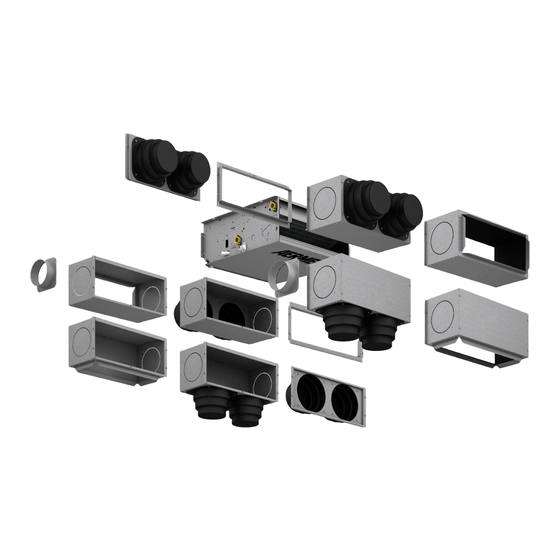
ANLAGENBEISPIELE Legende: Wassertemperatursonde Raumtemperatursonde VC/F Ventil (Heizung / Kühlung) Wärmetauscher (Heizung / Kühlung) Ventil (Heizung) Wärmetauscher (Heizung) 2-Leiter-Anlage mit Wassersonde 2-Leiter-Anlage ohne Wassersonde VC/F VC/F VC/F VC/F 4-Leiter-Anlage mit Wassersonde 4-Leiter-Anlage ohne Wassersonde VC/F VC/F VC/F VC/F VC/F HAUPTKOMPONENTEN 1 Luftzufuhr 9 Kondensatablass 17 Luftfilter (Ansaugung) 2 Frame (tragende Struktur) -
Page 40: Beschreibung Der Komponenten
EINSATZORT HINWEISE FÜR DIE QUALITÄT DES ZIRKULIERENDEN WASSERS IN DEN WÄRMETAUSCHERN Die Geräte wurden für die Installation in geschlossenen Räumen unter “städtischen”, nicht-marinen Bedingungen und mit nicht-ätzenden und nicht-staubenden Es wird empfohlen, eine Analyse des Wassers, das in dem Wärmetauscher zirkuliert, Eigenschaften entworfen. -
Page 41: Grenzwerte Für Den Gerätebetrieb
GRENZWERTE FÜR DEN GERÄTEBETRIEB Maximale Wassereintrittstemperatur °C Empfohlene maximale Wassereintrittstemperatur °C Maximaler Betriebsdruck (800 kPa) Mindestwasserdurchsatz (Hauptwärmetauscher) Maximaler Wasserdurchsatz (Hauptwärmetauscher) 1500 1500 1500 1500 1500 1500 3000 4000 Mindestwasserdurchsatz (Wärmetauscher für reinen Heizbetrieb) Maximaler Wasserdurchsatz (Wärmetauscher für reinen Heizbetrieb) 1000 Raumtemperaturgrenzen (Ta) °C 0°... -
Page 42: Hinweise Zur Installation
HINWEISE ZUR INSTALLATION und der elektrische Schaltkreis müssen sekonvektoren werden mit den Anschlüs- ACHTUNG: Vergewissern Sie sich, bereits vorbereitet sein. sen an die Standard-Drehzahlen geliefert. dass die Stromversorgung des Gerätes Der Gebläsekonvektor muss so installiert Ziehen Sie den Schaltplan zu Rate, bevor Sie unterbrochen ist, bevor Sie Eingriffe an werden, dass sich die Luft im ganzen Raum die Anschlüsse am Motor ändern. -
Page 43: Wasseranschlüsse • Kondensatablass
WASSERANSCHLÜSSE - Verlegen Sie die Wasseranschlüsse. ACHTUNG: Zum Befestigen der Rohr- leitungen immer einen Schrauben- schlüssel und Konterschlüssel verwen- den. Position, Typ und Durchmesser der Was- seranschlüsse finden Sie bei den Abmes- sungsangaben. Es empfiehlt sich die Wasserleitungen gut zu isolieren und / oder die als Zubehör erhältliche zusätzliche Kondensatauf- fangwanne zu installieren, um zu ver- meiden, dass während des Kühlbetriebs... -
Page 44: Elektrische Anschlüsse
ELEKTRISCHE ANSCHLÜSSE Das Gerät muss direkt an einen Strom- Verwenden Sie Kabel vom Typ H05V-K ACHTUNG: Überprüfen Sie, ob das anschluss oder an einen unabhängi- oder N07V-K mit Isolierung 300/500 V, die Bedienelement der Ladung des Elektro- gen Stromkreis angeschlossen wer- in Rohr oder Führungsschiene einge- motors standhält, ansonsten muss zwi- den. -
Page 45: Rotation Des Wärmetauschers
VES 3 Velocità - Speed - Vitesse- Geschwindigkeit-Velocidad Collegamento Motore - Connection to Motor - Connexion à moteur- Verbindung zum Motor - Conexión a Motor STANDARD High High High High High ROTATION DES WÄRMETAUSCHERS Ist bedingt durch die Anordnung der ROTATIONSSCHEMA DES WÄRMETAUSCHERS Wasseranschlüsse das Drehen des VES030... - Page 46 Fabricado con materiales de calidad superior y en total conformidad con las normativas de seguridad, VES es fácil de usar y podrá disfrutarlo durante mucho tiempo. La serie de fan coils VES está diseñada para ser integrada en el sistema VMF. VMF (Variable Multi Flow) es el sistema en condiciones de gestionar de modo inteligente una instalación hidrónica completa, compuesta por un refrigerador/bomba de calor, una caldera, una red de fan coils (multivelocidad o modulación continua de la velocidad) subdivididos...
-
Page 47: Información Importante • Mantenimiento • Embalaje • Uso
INFORMACIÓN IMPORTANTE Y MANTENIMIENTO ATENCIÓN: El fan coil está conectado a tes del fan coil. No vaporice agua en las metálicos), de todas formas, esto no indi- la red eléctrica y al circuito hidráulico: superficies externas ni en las internas ca un mal funcionamiento y no provo- cualquier intervención por parte de del aparato (podrían causarse cortocir-... -
Page 48: Descripción De La Unidad
DESCRIPCIÓN DE LA UNIDAD OBJETIVO DE LOS FAN COILS VES El ventilador de VES, diseñado para adaptarse a cualquier tipo de plantas dispositivos canalizados no son accesibles al público. Especialmente la posibilidad de integrarlos al sistema VMF permite controlar desde un único fan coil con accesorios hasta el VES incorporado a redes complejas de fan coils y sus accesorios. -
Page 49: Ejemplos De Instalación • Componentes Principales
EJEMPLOS DE INSTALACIÓN Leyenda: Sonda temperatura del agua Sonda temperatura ambiente VC/F Válvula (Calentamiento / Enfriamiento) Batería (Calentamiento / Enfriamiento) Válvula (Calentamiento) Batería (Calentamiento) Instalación 2 tubos sin sonda de agua Instalación 2 tubos con sonda de agua VC/F VC/F VC/F VC/F Instalación 4 tubos sin sonda de agua... -
Page 50: Descripción De Los Componentes
AMBIENTE DE FUNCIONAMIENTO ADVERTENCIAS SOBRE LA CALIDAD DEL AGUA QUE CIRCULA EN LAS BATERÍAS Las unidades están diseñadas para ser instaladas en ambientes cerrados, con atmósfera ‘urbana’ no marina, donde no haya corrosión ni polvo. Se aconseja efectuar un análisis del agua que circula en la batería Nunca se deben superar las siguientes concentraciones de factores apuntando a la presencia de bacterias (detección de bacterias del hierro contaminantes en el aire donde debe funcionar la unidad:... -
Page 51: Límites De Funcionamiento
LÍMITES DE FUNCIONAMIENTO Temperatura máxima de entrada de agua °C Máxima temperatura de entrada de agua recomendada °C Presión máxima de funcionamiento (800 kPa) Mínimo caudal de agua (Batería principal) Máximo caudal de agua (Batería principal) 1500 1500 1500 1500 1500 1500 3000... -
Page 52: Información Para La Instalación • Instalación De La Unidad
INFORMACIÓN PARA LA INSTALACIÓN ATENCIÓN: antes de realizar cualquier tuberías del agua, de la descarga del conexiones correspondientes a las velo- intervención, controlar que esté des- agua de condensación y del circuito cidades estándar. Consultar el esquema conectada la alimentación eléctrica. eléctrico. -
Page 53: Conexiones Hidráulicas • Conexiones Para Descarga De Condensación
CONEXIONES HIDRÁULICAS - Hacer las conexiones hidráulicas. ATENCIÓN: Utilizar siempre llave y contra- llave para fijar las tuberías. La posición, el tipo y el diámetro de las conexiones hidráulicas se indican en los datos de las dimensiones. Se recomienda aislar adecuadamente las tuberías del agua y/o instalar la correspon- diente cubeta auxiliar de recolección del agua de condensación, disponible como... -
Page 54: Conexiones Eléctricas
CONEXIONES ELÉCTRICAS La unidad se debe conectar directa- CARACTERÍSTICAS DE LOS CABLES DE ATENCIÓN: Controlar que el tablero de mente a una red eléctrica o a un cir- CONEXIÓN mandos soporte la carga del motor cuito independiente. Utilizar cables H05V-K o N07V-K con aisla- eléctrico, caso contrario colocar una ATENCIÓN: es obligatorio conectar miento para 300/500 V, tendidos dentro... -
Page 55: Rotación De La Batería
VES 3 Velocità - Speed - Vitesse- Geschwindigkeit-Velocidad Collegamento Motore - Connection to Motor - Connexion à moteur- Verbindung zum Motor - Conexión a Motor STANDARD High High High High High ROTACIÓN DE LA BATERÍA Si se debiese girar la batería para facilitar las ESQUEMA DE ROTACIÓN DE LA BATERÍA conexiones hidráulicas, proceder como se VES030... -
Page 56: Dimensions
DIMENSIONI • DIMENSIONS • DIMENSIONS • ABMESSUNGEN • DIMENSIONES [mm] Attacchi idraulici batteria principale (femmina) Main coil water connections (female) Raccords hydrauliques de la batterie principale (femelle) Wasseranschlüsse für Hauptwärmetauscher (Innengewinde) Conexiones hidráulicas batería principal (hembra) Ø 3/4"G 3/4"G 3/4"G 3/4"G 3/4"G 3/4"G... -
Page 57: Wiring Diagrams
SCHEMI ELETTRICI • WIRING DIAGRAMS • SCHEMAS ELECTRIQUES • SCHALTPLÄNE • ESQUEMAS ELÉCTRICOS LEGENDA • READING KEY • LEGENDE • LEGENDE • LEYENDA AL = Alimentatore 12V MV = Motore ventilatore • Fan motor VF = Valvola solenoide freddo Power supply 12V Moteur ventilateur •... - Page 58 SCHEMI ELETTRICI • WIRING DIAGRAMS • SCHEMAS ELECTRIQUES • SCHALTPLÄNE • ESQUEMAS ELÉCTRICOS VES 030 - 040 - 130 - 140 - 230 - 240 VES 330 - 340 SCHEMA DI COLLEGAMENTO MOTORE SCHEMA DI COLLEGAMENTO MOTORE MOTOR CONNECTION DIAGRAM MOTOR CONNECTION DIAGRAM SCHEMA DE RACCORDEMENT MOTEUR SCHEMA DE RACCORDEMENT MOTEUR...
- Page 59 SCHEMI ELETTRICI • WIRING DIAGRAMS • SCHEMAS ELECTRIQUES • SCHALTPLÄNE • ESQUEMAS ELÉCTRICOS VMF_E1 + VMF-E2/E4 VMF-E1 + VMF-E5 + VMF-E2/E4 MODBUS VMF-E4 12Vdc (E5) 0Vdc VMF-E4 CN27 CN17 CN16 CN27 CN17 CN16 SLOT EXPANSION SLOT EXPANSION CN23 CN22 CN25 CN26 CN23 CN22...
- Page 60 SCHEMI ELETTRICI • WIRING DIAGRAMS • SCHEMAS ELECTRIQUES • SCHALTPLÄNE • ESQUEMAS ELÉCTRICOS VMF-E4 CN27 CN17 VMF-E0 CN7-B CN7-A BL NE MA RO VC/F 230V 50Hz VMF-E0 (master + slave) (---------------------------------------------------------------------------------------------------------- 30 m MAX ------------------------------------------------------------------------------------------------------) E0/1 Slave VMF-E4 Master Slave 1 E0 Master E0 Master CN27...
- Page 61 SCHEMI ELETTRICI • WIRING DIAGRAMS • SCHEMAS ELECTRIQUES • SCHALTPLÄNE • ESQUEMAS ELÉCTRICOS WMT10 + VCF 2 tubi 2 tube 2 tuyaux 2 Röhren 2 tubos WMT10 + VF + VC 4 tubi 4 tube 4 tuyaux 4 Röhren 4 tubos Gli schemi elettrici sono soggetti ad un continuo aggiornamento, è...
- Page 62 SCHEMI ELETTRICI • WIRING DIAGRAMS • SCHEMAS ELECTRIQUES • SCHALTPLÄNE • ESQUEMAS ELÉCTRICOS FMT10 + VCF 2 tubi 2 tube 2 tuyaux 2 Röhren 2 tubos FMT10 + VF + VC 4 tubi 4 tube 4 tuyaux 4 Röhren 4 tubos Gli schemi elettrici sono soggetti ad un continuo aggiornamento, è...
- Page 63 SCHEMI ELETTRICI • WIRING DIAGRAMS • SCHEMAS ELECTRIQUES • SCHALTPLÄNE • ESQUEMAS ELÉCTRICOS FMT20AW + VCF 2 tubi 2 tube 2 tuyaux 2 Röhren 2 tubos FMT20AW + VF + VC 4 tubi 4 tube 4 tuyaux 4 Röhren 4 tubos Gli schemi elettrici sono soggetti ad un continuo aggiornamento, è...
- Page 64 SCHEMI ELETTRICI • WIRING DIAGRAMS • SCHEMAS ELECTRIQUES • SCHALTPLÄNE • ESQUEMAS ELÉCTRICOS PXAE Gli schemi elettrici sono soggetti ad un continuo aggiornamento, è obbligatorio quindi fare riferimento a quelli a bordo macchina. A l l w i r i n g d i a g r a m s a r e c o n s t a n t l y...
- Page 65 SCHEMI ELETTRICI • WIRING DIAGRAMS • SCHEMAS ELECTRIQUES • SCHALTPLÄNE • ESQUEMAS ELÉCTRICOS PXAE SIT3 + SIT5 Gli schemi elettrici sono soggetti ad un continuo aggiornamento, è obbligatorio quindi fare riferimento a quelli a bordo macchina. A l l w i r i n g d i a g r a m s a r e c o n s t a n t l y...
-
Page 66: Soluzione Dei Problemi
PROBLEMA • PROBLEM PROBABILE CAUSA • PROBABLE CAUSE SOLUZIONE • REMEDY PROBLEME • PROBLEM CAUSE PROBABLE • MÖGLICHE URSACHE SOLUTION • ABHILFE PROBLEMA CAUSA PROBABLE SOLUCIÓN Poca aria in uscita. Errata impostazione della velocità sul pannello comandi. Scegliere la velocità corretta sul pannello comandi. Feeble air discharge. -
Page 67: Mise Hors Service Et Démantèlement Des Composants De La Machine
DATI IN ACCORDO CON IL REGOLAMENTO EU 2016/2281 • DATA IN ACCORDANCE WITH EU REGULATION 2016/2281 • DONNÉES SELON LA RÉGLE- MENTATION DE L’UE 2016/2281 • DATEN GEMÄSS EU 2016/2281-VERORDNUNG • DATOS SEGÚN LA REGULACIÓN DE LA UE 2016/2281 VES 030-340 IMPIANTO A DUE TUBI - TWO-PIPE-SYSTEM - SYSTÈME À... -
Page 68: Garanzia Di 3 Anni
Aermec reserves the right to make all modification deemed necessary for improving the product at any time with any modification of technical data. L’Aermec se réserve la faculté d’apporter à tout moment toutes les modifications estimées nécessaires pour l’amélioration du produit avec éventuelle modifi- cation des données techniques.