Table des Matières
Publicité
Les langues disponibles
Les langues disponibles
Liens rapides
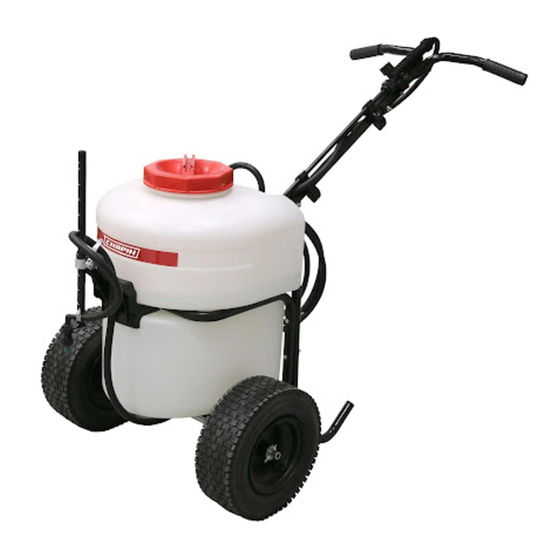
12 Gallon Battery-Operated Push Sprayer
See website for
warranty details
Model
97902
DO NOT RETURN TO STORE. CALL
CHAPIN CUSTOMER SERVICE:
800-950-4458
www.chapinmfg.com
Due to our ongoing product improvement process, product specifications may change without notice. U.S. and foreign patents pending.
016243 R0918
Publicité
Table des Matières

Manuels Connexes pour Chapin 97902


Sommaire des Matières pour Chapin 97902
-
Page 25: Pulvérisateur À Pousser Alimenté Par Batterie De 12 Galons
Modèle 97902 NE PAS RETOURNER EN MAGASIN APPELER LE SERVICE À LA CLIENTÈLE DE CHAPIN : 800-950-4458 www.chapinmfg.com À cause de notre processus d’amélioration continue de produits, les spécifications de produits pourraient changer sans préavis. Brevets américains et étrangers en instance. - Page 26 REMARQUE : la cuve et le boyau peuvent contenir de l’eau résiduelle suite au test de qualité du pulvérisateur. AVERTISSEMENT Ce vaporisateur est conçu pour être utilisé SEULEMENT avec la batterie au lithium-ion de 24 V de Chapin. Toute autre batterie peut causer des blessures graves à l’utilisateur et d’importants dommages au pulvérisateur.
-
Page 27: Indicateur Du Niveau De Charge De La Batterie
2. Un entreposage prolongé ne nuira pas à la batterie ou au chargeur. PROCÉDURE DE CHARGEMENT Les chargeurs Chapin sont conçus pour charger les batteries Chapin en 3,5 à 4 heures, selon celle qu’on recharge. 1. Brancher le chargeur dans une prise qui convient avant d’insérer la batterie. -
Page 28: Installer Et Enlever La Batterie Du Pulvérisateur
AVERTISSEMENT : Risque de décharge électrique. Ne laisser aucun liquide pénétrer le chargeur. AVERTISSEMENT : Risque de brûlure. Pour réduire le risque de blessure, ne charger que les batteries désignées par Chapin. Les autres types de batterie risquent d’exploser, ce qui pourrait causer des blessures personnelles et des dommages. -
Page 29: Installation Du Pied Du Cadre
INSTALLATION DU PIED DU CADRE Fixez le pied du cadre (C-8 et C-9) à l’aide des boulons et écrous (H-1) au réservoir (C-2). Installez les capuchons d’extrémité (H-12) dans les pieds du cadre (C-8 et C-9). H-12 H-12 INSTALLATION DU GUIDON Passer le faisceau de câbles de l’interrupteur marche/arrêt (C-4) dans le tube du guidon (C-5). -
Page 30: Assembler L'élément Filtrant Et Le Couvercle
Verrouillez les boulons pinces de tube (H-9) sur le tube du guidon (C-5). ASSEMBLER L’ÉLÉMENT FILTRANT ET LE COUVERCLE Insérer l’élément filtrant (C-16) et visser le couvercle (C-17). C-17 C-16... -
Page 31: Assembler Les Poignées Et L'interrupteur Marche/Arrêt
ASSEMBLER LES POIGNÉES ET L’INTERRUPTEUR MARCHE/ARRÊT Connectez le faisceau de câbles marche/arrêt (C-4) à l’interrupteur et insérez le support de l’interrupteur (H-10) dans le tube de guidon carré (C-5). Boulonnez les poignées droite (C-10) et gauche (C-11) au tube du guidon à l’aide des boulons (H-1). Pour terminer, insérez les manchons antidérapants (H-11) sur les poignées (C-10 et C-11). -
Page 32: Assembler Le Support De Buse Réglable
ASSEMBLER LE SUPPORT DE BUSE RÉGLABLE Assemblez le support de blocage de came (H-4) avec les écrous et boulons fournis de (H-4) au support de buse (C-7). Fixez ensuite le porte-buse (H-2) à la barre de buse (C-6) comme indiqué.). Assembled ATTACHEZ LE SUPPORT DE BUSE ET LA BUSE RÉGLABLE AU RÉSERVOIR À... -
Page 33: Assembler La Décharge À La Vanne De Répartition
ASSEMBLER LA DÉCHARGE À LA VANNE DE RÉPARTITION Raccordez la décharge avec le tuyau (C-15) à la vanne de dérivation, comme indiqué. Passez le tuyau dans le collier de serrage (H-8) (Figure A). Assemblez le collet à vis sans fin (H-5) au tuyau (Figure B). Assemblez le tuyau à la vanne de répartition (Figure C). Serrer la pince à vis sans fin et la pince à... -
Page 34: Remplir Le Pulvérisateur
REMPLIR LE PULVÉRISATEUR Assurez-vous que le panier-filtre est en place pour empêcher les débris d’entrer dans le réservoir. Déterminez la quantité de mélange nécessaire pour votre application. Ajoutez la bonne quantité d’eau au réservoir. Ajoutez la bonne quantité de produits chimiques au réservoir (vérifiez l’étiquette des produits chimiques pour connaître le bon rapport des produits). Remuez le mélange dans le réservoir avec un accessoire propre (comme un agitateur de peinture). -
Page 35: Passez De La Pulvérisation À Rampe À La Pulvérisation Localisée
PASSEZ DE LA PULVÉRISATION À RAMPE À LA PULVÉRISATION LOCALISÉE Placez l’interrupteur à l’option de pulvérisation souhaitée. B O O M S P O T RÉGLAGE DU SCHÉMA DE PULVÉRISATION POUR LA PULVÉRISATION POUSSÉE Pulvérisez facilement à gauche ou à droite avec le porte-lance positionnable intégré dans le bouchon. Spray Right Spray left AJUSTEZ LA HAUTEUR DE LA BUSE... -
Page 36: Replacement Parts Partes De Repuesto Pièces De Rechange
24V Battery, Batería 24V, Batterie 24V 800-950-4458 CHAPIN CUSTOMER SERVICE: CHAPIN INTERNATIONAL, INC. P.O. BOX 549 700 ELLICOTT ST. BATAVIA, NY 14021-0549 Due to our ongoing product improvement process, product specifications may change without notice. U.S. and foreign patents pending.