Télécharger Imprimer la page

Publicité

Les langues disponibles

Les langues disponibles

Liens rapides

Montageanleitung
Installation instructions
Notice de montage
AS-i Modul
AS-i module
Module AS-i
AC2518
AC2519

Publicité

loading

Sommaire des Matières pour IFM Electronic AS-interface AC2518

  • Page 1 Montageanleitung Installation instructions Notice de montage AS-i Modul AS-i module Module AS-i AC2518 AC2519...
  • Page 2 Bestimmungsgemäße Verwendung Der Slave bekommt Daten über das AS-Interface und wandelt diese in analoge Ausgangssignale. Das AS-i Modul fungiert als Slave mit bidirektionalem Datenverkehr im AS-i Netz. Die Datenübertragung zum Host erfolgt asynchron nach dem AS-i Profil S-7.3, gemäß AS-i Spezifikation V2.1. •...
  • Page 3 LED Infrarot-Empfänger Fixierung IR-Adapter LED rot FAULT LED grün PWR Beschriftungsfeld M12 Buchse LED grün AUX 4x LED gelb Analogausgänge Pin 1: AO+ Analogausgang Pin 2: n.c. Pin 3: AO- Analogausgang 0V Pin 4: n.c. Pin 5: Funktionserde Elektrischer Anschluß Das Analogmodul wird über die standardisierte EMS (Versorgung aus AS-i) oder aus der E-EMS (Versorgung aus ext.
  • Page 4 Anschlußbelegungen Bei allen folgenden Anschlußbelegungen bezieht sich die dargestellte Pinbelegung auf das Analogmodul. Die Analogausgänge AO- dürfen weder direkt noch indirekt (über den angeschlossenen Aktuator) miteinander verbunden werden. Anschluß eines Aktuators mit Stromausgang (AC2518) Analogmodul 2-Draht Aktuator Pin 1: AO+ Analogausgang Pin 2: n.c.
  • Page 5 Betrieb Prüfen Sie, ob das Gerät sicher funktioniert. Anzeige durch LEDs: • LED gelb AO1...AO4 an: Analoges Signal im Messbereich bzw. kein Aktuator angeschlos- sen. Es ist keine Unterscheidung möglich, ob das 0V/0mA-Signal anliegt oder kein Aktuator ange- schlossen ist. •...
  • Page 6 Analogausgangsmodul 0 ... 10V - AC2519 Bereich Einheiten Einheiten LED AO1...AO4 Bedeutung 0 ... 10V dez. hex. Analog 0 ... 10V 0000 ... 10000 0000 ... 2710 Nennbereich 10,001V ... 10001 ... 11500 2711 ... 2CEC Übersteuerungs- 11,5V bereich > 11,5V 11500 >...
  • Page 7 Function and features The slave converts analogue input signals and transfers them to the AS-i master via the AS-Interface. The AS-i module operates as a slave with bidirectional data transfer in the AS-i network. The data transfer to the host is asynchronous according to the AS-i pro- file S-7.3 and the AS-i specification V2.1.
  • Page 8 LED infrared reciever fixture infrared adapter LED red FAULT LED green PWR label M12 socket LED green AUX 4x LED yellow analogue outputs Pin 1: AO+ analogue output Pin 2: n.c. (not connected) Pin 3: AO- analogue output 0V Pin 4: n.c. (not connected) Pin 5: functional earth Electrical connection The analogue module is connected to the AS-Interface via the stan-...
  • Page 9 Wiring For all the following wiring diagrams the indicated pin connection refers to the analogue module. The analogue outputs AO- must neither directly nor indirectly (via the connected actuator) be connected to each other. Connection of an actuator with current output (AC2518) Analogue module 2-wire actuator Pin 1: AO+ analogue output...
  • Page 10 Operation Check the safe functioning of the unit. Display by LEDs: • LED yellow AO1...AO4 on: analogue signal in the measuring rangeor no actuator connected. It cannot be differentiated whether the 0V signal is applied or whether an actuator is con- nected •LED yellow AO1...AO4 flashes: analogue signal outside the...
  • Page 11 Analogue output module 0 ... 10V - AC2519 Range Units Units LED AO1...AO4 Meaning 0 ... 20mA dec. hex. analogue 0mA ... 20mA 0000 ... 20000 0000 ... 4E20 nominal range 20.001mA ... 20001 ... 23000 4E21 ... 59D8 above nominal 23mA range >...
  • Page 12 Fonctionnement et caractéristiques L'esclave convertit les signaux d'entrée analogiques et les transmet au maître AS-i via l'interface AS-i. Le module AS-i est un esclave avec transmission bidirectionnelle des données via le réseau AS-i. La transmission des données à l'hôte est asynchrone selon le profil AS-i S-7.3, selon la spécification AS-i V2.1.
  • Page 13 
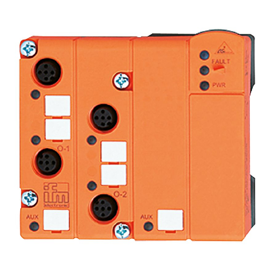
LED récepteur infrarouge fixation adaptateur infrarouge LED rouge FAULT LED verte PWR étiquettes prise M12 LED verte AUX 4x LED jaune entrée analogique broche 1: sortie analogique broche 2: n.c. broche 3: sortie analogique 0V broche 4: n.c. broche 5: terre fonctionnelle Raccordement électrique Le module analogique est raccordé...
  • Page 14 Raccordement Pour tous les raccordements suivants le raccordement indiqué se réfè- re au module analogique. Les sorties analogiques 0V ne doivent pas être interconnectées ni directement ni indirectement (via l'actionneur raccordé). Raccordement d'un actionneur avec sortie courant (AC2518) module analogique Actionneur 2 fils broche 1: sortie analogique broche 2: n.c.
  • Page 15 Fonctionnement Vérifier le bon fonctionnement du module. Affichage par LED: • LED jaune AS1...AS4 allumée: signal analogique dans la plage de mesure ou pas d'actionneur raccordé. Il ne peut être distin- gué si le signal 0V est présent ou si un actionneur est raccordé. •...
  • Page 16 Module de sortie analogique 0 ... 10V - AC2519 Plage Unités déc. Unités hexa LED AO1...AO4 Signification 0 ... 10V analogique 0 ... 10V 0000 ... 10000 0000 ... 2710 allumée plage nominale 10,001V ... 10001 ... 11500 2711 ... 2CEC allumée au-dessus de la 11,5V...

Ce manuel est également adapté pour:

As-interface ac2519