Publicité

Les langues disponibles

Les langues disponibles

Liens rapides

Montageanleitung
Installation instructions
Notice de montage
AS-i Modul
AS-i module
Module AS-i
AC2509 / AC2559

Publicité

Table des Matières
loading

Sommaire des Matières pour IFM Electronic AS interface AC2509

  • Page 1 Montageanleitung Installation instructions Notice de montage AS-i Modul AS-i module Module AS-i AC2509 / AC2559...
  • Page 2: Bestimmungsgemäße Verwendung

    Bestimmungsgemäße Verwendung • AS-i-Profil S-7.0.E • maximale Anzahl von Modulen pro Master: 31 • AS-Interface Version 2.1 Bedien- und Anzeigeelemente LEDs Fixierung für IR-Adapter 8 Buchsen M12 Beschriftungsfelder Montage Montieren Sie das Modul auf ein verdrahtetes Modul-Unterteil des AS-i Netzes, Anzugsdrehmoment 0,8Nm. Technische Daten Sie können das Datenblatt bei Bedarf unter der Internetadresse www.ifm.com herunterladen.
  • Page 3 LED3 Infrarot-Empfänger LED2 rot FAULT Fixierung IR-Adapter LED grün PWR Spannungs- 8x LED1 gelb versorgung o.k LED grün Hilfsspannung Ausgänge Eingänge M12-Buchse M12-Buchse Schaltausgang + Sensorversorgung L+ Externe Spannung - Sensorversorgung L- Funktionserde Dateneingang n.c. Funktionserde Adressieren Vergeben Sie eine freie Adresse zwischen 1 und 31, Auslieferungs- adresse ist 0.
  • Page 4 Das Modul kann in Verbindung mit dem FK-E Unterteil AC5011 (mit Adressierbuchse) über das Adressierkabel (E70213) in montiertem und verdrahtetem Zustand adressiert werden. In Verbindung mit dem FK-E Unterteil AC5003 (ohne Adressierbuchse) muss das Modul erst über das Adressiergerät AC1144 adressiert und dann montiert werden.
  • Page 5: Function And Features

    Function and features • AS-i profile: S-7.0.E • maximum number of modules per master: 31 • AS-interface version 2.1 Operating and display elements LEDs fixture infrared adapter 8 sockets M12 labels Mounting Mount the module onto the wired module lower part of the AS-i net- work, tightening torque 0.8Nm.
  • Page 6 LED3 infrared reciever LED2 red FAULT fixture infrared adapter LED green PWR sensor 8x LED1 supply o.k yellow LED green auxiliary voltage outputs inputs Socket M12 Socket M12 switching output + sensor supply L+ external power - sensor supply L- functional earth data input not connected...
  • Page 7 If the mounted and wired module is used with the FC-E lower part AC5011 (with addressing socket), it can be addressed via the address- ing cable (E70213). If it is used with the FC-E lower part AC5003 (without addressing sock- et) the module must first be addressed via the addressing unit AC1144 and then mounted onto the lower part.
  • Page 8: Fonctionnement Et Caractéristiques

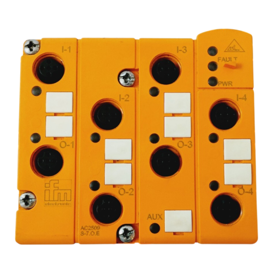
    Fonctionnement et caractéristiques • Profil AS-i S-7.0.E • nombre maximal de modules par maître: 31 • version AS-interface 2.1 Eléments de service et d’indication fixation adaptateur infrarouge 8 prises M12 étiquettes Montage Monter le module sur l'embase de câblage raccordé au réseau AS-i, couple de serrage 0,8Nm.
  • Page 9: Adressage

    LED3 récepteur infrarouge LED2 rouge FAULT fixation adapta- teur infrarouge LED verte PWR alimentation 8x LED1 capteur o.k jaunes LED verte tension auxiliaire sorties entrées Prise M12 broche Prise M12 broche alimentation capteur L+ sortie de commutation + alimentation capteur L- alimentation externe - entrée données terre fonctionelle...
  • Page 10: Adressage Infrarouge

    Si le module monté et câblé est utilisé avec l'embase pour câble plat FK-E AC5011 (avec prise d'adressage), il peut être adressé via le cor- don d'adressage (E70213). Si le module est utilisé avec l'embase pour câble plat FK-E AC5003 (sans prise d'adressage) il doit d'abord être adressé...
  • Page 11 Electrical ratings I/O ClassicLine module (AC2509) Power supply Input Rating Output Rating 30V DC, 200mA 4 channels 31.6V DC 10...30V DC 30V DC, 700mA 250mA per channel / 2A total load...

Ce manuel est également adapté pour:

As interface ac2559

Table des Matières