Télécharger Imprimer la page

Publicité

Les langues disponibles

Les langues disponibles

Liens rapides

Montageanleitung
Installation Instructions
Notice de Montage
AS-i Modul
AS-i module
Module AS-i
AC2520 / AC2570

Publicité

loading

Sommaire des Matières pour IFM Electronic AS-interface AC2520

  • Page 1 Montageanleitung Installation Instructions Notice de Montage AS-i Modul AS-i module Module AS-i AC2520 / AC2570...
  • Page 2 Bestimmungsgemäße Verwendung Der AS-i Slave wandelt analoge Signale (Temperaturwerte) in digitale Werte um und überträgt diese zum Host. Die Datenübertragung erfolgt asynchron nach dem AS-i Profil S-7.3, gemäß AS-i Spezifikation V2.1. – • Sensorversorgung aus AS-i • Messwertwandlung für 4 Kanäle: 480 ms •...
  • Page 3 LED Infrarot-Empfänger Fixierung IR-Adapter LED rot FAULT LED grün PWR Beschriftungsfeld M12 Buchse 4x LED gelb Analogeingänge Pin 1: S + Pin 2: AI + Pin 3: S - Pin 4: AI - Pin 5: Abschirmung (Funktionserde) Elektrischer Anschluss Das Analogmodul wird über die standardisierte EMS (Versorgung aus AS-i) an das AS-Interface angeschlossen.
  • Page 4 Anschluss eines 4-Draht-Pt100-Elementes an das AS-i Modul 4-Draht Pt100 Analogmodul Pin 1: S + Pin 2: 1+ ... 4+ Pin 3: S - Pin 4: 1 - ... 4 - Pin 5: Abschirmung Pt100 (Funktionserde) 4-Draht-Pt100-Sensoren liefern genauere Resultate als 2-Draht-Senso- ren, vorausgesetzt, dass die Zuleitungen in ihrem Widerstand gleich sind.
  • Page 5 Parametrierung der Analogmodule Parameterbit/ Beschreibung Bemerkungen Bezeichnung 50 Hz Filter im A/D Wandler aktiv Das 50 Hz Filter gilt für ganz Europa Filter 60 Hz Filter im A/D Wandler aktiv Peripheriefehler kann ausgelöst Parameterbit werden von P1, P2 Peripheriefehler 2-Leiter Modus Typ des 4-Leiter Modus Pt100 Element...
  • Page 6 • LED rot FAULT AS-i Kommunikationsfehler, z. B. Slaveadresse 0 blinkend: Peripheriefehler * * Peripheriefehler Ein Peripheriefehler wird angezeigt, wenn mindestens eines der Signa- le AI1, AI2, AI3 oder AI4 außerhalb des Messbereiches ist oder an min- destens einem analogen Kanal nichts angeschlossen ist. Messbereich des Pt100-Moduls Die Messbereiche, das Verhalten der LEDs und deren Bedeutung ent- nehmen Sie bitte der folgenden Tabelle:...
  • Page 7 Function and features The AS-i slave converts analogue signals (temperature values) into dig- ital values and transfers them to the host. The data transfer is asynchronous according to the AS-i profile S-7.3 and the AS-i specification V2.1. • Sensor supply from AS-i •...
  • Page 8 LED Infrared reciever fixture infrared adapter LED red FAULT LED green PWR label M12 socket 4x LED yellow analogue inputs Pin 1: S + Pin 2: AI + Pin 3: S - Pin 4: AI - Pin 5: screen (functional earth) Electrical connection The analogue module is connected to the AS-Interface via the stan- dardised EMS [(supply from AS-i) (also in this case the Pt100 sensors...
  • Page 9 Connection of a 4-wire Pt100 element to the AS-i module Analogue modul 4-wire Pt100 Pin 1: S + Pin 2: AI + Pin 3: S - Pin 4: AI - Pin 5: screen (functional earth) Pt100 4-wire Pt100 sensors supply more exact results than 2-wire sensors provided that the wire resistance is the same.
  • Page 10 Parameter setting of the analogue modules Parameter bit/ Description Comments Designation 50 Hz filter in the A/D converter active The 50 Hz filter applies filter to the whole of Europe 60 Hz filter in the A/D converter active Periphery fault can be triggered by Parameter bit P1, P2 periphery fault...
  • Page 11 • LED rot FAULT AS-i communication error e.g. slave address 0 flashing: periphery fault * * periphery fault A periphery fault is indicated if at least one of the signals AI1, AI2, AI3 or AI4 is outside the measuring range or if nothing is connected to at least one analogue channel.
  • Page 12 Fonctionnement et caractéristiques L'esclave AS-i convertit les signaux analogiques (valeurs de température) en valeurs numériques et les transmet au maître AS-i. La transmission des données est asynchrone selon le profil AS-i S-7.3, selon la spécification AS-i V2.1. • alimentation des capteurs via AS-i •...
  • Page 13 
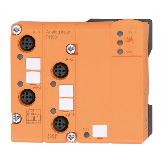
LED récepteur infrarouge fixation adaptateur infrarouge LED rouge FAULT LED verte PWR étiquettes prise M12 4x LED jaune entrée analogique broche 1: S + broche 2: 1+ ... 4+ broche 3: S - broche 4: 1 - ... 4 - broche 5: blindage (terre fonctionnelle) Raccordement électrique Le module analogique est raccordé...
  • Page 14 Raccordement d'un élément Pt100 4 fils au module AS-i 4 fils Pt100 module analogique Pin 1: S + Pin 2: AI + Pin 3: S - Pin 4: AI - Pin 5: blindage Pt100 (terre fonctionnelle) Les capteurs Pt100 4 fils fournissent des résultats plus exacts que les capteurs 2 fils si les fils ont la même résistance.
  • Page 15 Paramétrage des modules analogiques Bits de paramètres/ Description Remarques Désignation filtre 50 Hz actif dans le convertisseur A/N Le filtre 50 Hz est utilisé filtre dans toute l'Europe filtre 60 Hz actif dans le convertisseur A/N Défaut de périphérie peut être bits de paramètres déclenché...
  • Page 16 • LED rouge FAULT allumée: erreur de communication AS-i par ex. adresse d'esclave 0 clignotant: défaut de périphérie * * défaut de périphérie Un défaut de périphérie est affiché si au moins l'un des signaux AI1, AI2, AI3 ou AI4 est en dehors de la plage de mesure ou si rien n'est raccordé...

Ce manuel est également adapté pour:

As-interface ac2570