Table des Matières
Publicité
Les langues disponibles
Les langues disponibles
Liens rapides
Publicité
Table des Matières

Sommaire des Matières pour Autophix OBDMATE OM123
- Page 2 Table of Contents Engli h 6-17 Deutsch 18-28 Français 29-38 Español 39-50...
-
Page 3: Table Des Matières
2.1 On-Board Diagnostics (OBD) II 2.2 Diagnostic Trouble Codes (DTCs) 2.3 Location of the Data Link Connector (DLC) 2.4 OBD II Definitions 3. Using the Scan Tool 3.1 Tool Description OBDMATE OM123 3.2 Specifications 3.3 Included 3.4 Language 3.5 Contrast 3.6 Unit of Measure... - Page 4 1. Beschreibung und Funktion 2. Bestimmungsgemäßer Einsatz 3. Sicherheits-, Service- und Betriebshinweise 4. Bedien-, Anschluss- und Anzeigeelemente 5. Fehlercodes, Erklärungen und Aufbau (DTC) 6. Inbetriebnahme und Betrieb 6.1 Inbetriebnahme, OBD-Schnittstelle 6.2 Gerät individuell einstellen (Setup), Geräteinfo, Selbsttest 6.3 Fehlercodes auslesen 6.4 Fehlercodes löschen 6.5 Abgassystem-Überprüfung (I/M Readiness) 6.6 Echtzeitdaten auslesen (Data Stream)
- Page 5 1. Précautions d’usage............2. Informations ..............29 2 .1 (OBD) II diagnostic de bord............29 2 .2 Diagnostic des Codes erreurs (DTC) ..........30 2 .3 Localisation de la prise de diagnostic (DLC)........30 2 .4 OBD II Définitions..............31 3 . Utilisation de l’outil de diagnostic......32 3.1 Description de l’OM123.............32 3.2 Spécifications.
- Page 6 2.2 Códigos de diagnóstico de fallas (DTCs)........2.3 Ubicación del conector Data Link (DLC)........2.4 Definiciones de OBD II............3. Uso de la herramienta de escaneo ....... 3.1 Descripción de la herramienta OBDMATE OM123..... 3.2 Especificaciones..............3.3 Incluido................. 3.4 Idioma................... 3.5 Contraste................
-
Page 7: Safety Precautions And Warnings
1. Safety Precautions and Warnings To prevent personal injury or damage to vehicles and/or the scan tool, read this instruction manual first and observe the following safety precautions at a minimum whenever working on a vehicle: Always perform automotive testing in a safe environment Do not attempt to operate or observe the tool while driving a vehicle. -
Page 8: Diagnostic Trouble Codes (Dtcs)
system turns on a warning lamp (MIL) on the vehicle instrument panel to alert the driver typically by the phrase “Check Engine” or “Service Engine Soon”. The system will also store important information about the detected malfunction so that a technician can accurately find and fix the problem. Here below follow three pieces of such valuable Information: 1) Whether the Malfunction Indicator Light (MIL) is commanded “on”... -
Page 9: Location Of The Data Link Connector (Dlc)
2.3 Location of the Data Link Connector (DLC) The DLC (Data Link Connector or Diagnostic Link Connector) is the standardized 16-cavity connector where diagnostic scan tools interface with the vehicle's on-board computer. The DLC is usually located 12 inches from the center of the instrument panel (dash), under or around the driver's side for most vehicles. -
Page 10: Using The Scan Tool
DTC -Diagnostic Trouble Codes (DTC) these identify which section of the emission control system has malfunctioned. Freeze Frame Data -When an emissions related fault occurs, the OBD II system not only sets a code, but also records a snapshot of the vehicle operating parameters to help in identifying the problem. -
Page 11: Specifications
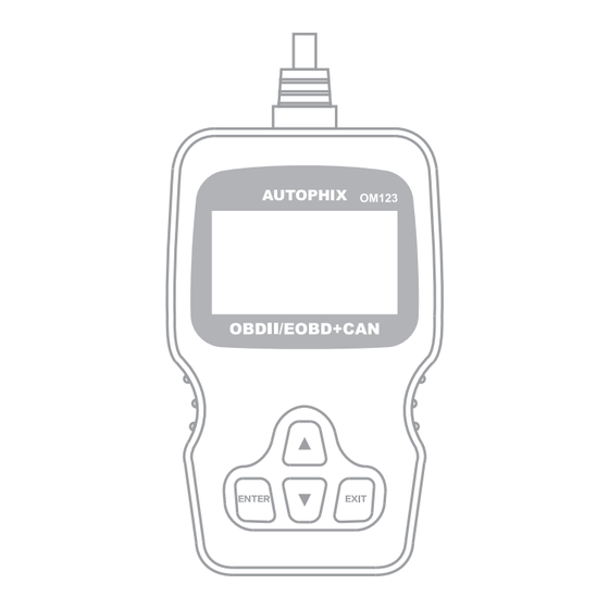
1. LCD DISPLAY – Indicates test results. Backlit, 128 x 64 pixel display with contrast adjustment. 2. ENTER BUTTON – Confirms a selection (or action) from a menu. 3. EXIT BUTTON – Cancels a selection (or action) from a menu or returns to the menu. -
Page 12: Language
3.4 Language 1) From the Main Menu, use the UP/DOWN scroll button to select the Language and press the ENTER button. 1) From the Main Menu, use the UP/DOWN scroll button to select Contrast, and press ENTER. 2) From the Contrast menu, use the UP/DOWN scroll button to increase or decrease contrast. - Page 13 1) From the Main Menu, use the UP/DOWN scroll button to select Unit of Measure, and press ENTER. 2) From the Unit of Measure menu, use the UP/DOWN scroll button to select the desired Unit of Measure. 3) Press the ENTER button to save your selection and return to the previousmenu.
-
Page 14: Read Codes
6) Press ENTER to confirm. A sequence of messages displaying the OBD II protocols will be observed on the display until the vehicle protocol is detected. If the scan tool fails to communicate with the vehicle's ECU (Engine Control Unit), a "LINKING ERROR!" message shows up on the display. Verify that the ignition is ON;... -
Page 15: Erase Codes
4.2 Erase Codes Notes: This function is performed with key on engine off . Do not start the engine. Before performing this function, make sure to retrieve and record the trouble codes. After clearing, you should retrieve trouble codes once more or turn ignition on and retrieve codes again. - Page 16 if DTCs were erased, View Freeze Data may not be stored in vehicle memory depending on vehicle. Use the UP/DOWN scroll button for more PIDs if an arrow appears on the screen. Press EXIT to return to Diagnostic Menu. I/M refers to Inspection and Maintenance, that is legislated by the Government to meet federal clean-air standards.
-
Page 17: Warranty And Service
Final determination of defects shall be made by AUTOPHIX in accordance with procedures established by AUTOPHIX. No agent, employee, or representative of AUTOPHIX has any authority to bind AUTOPHIX to any... -
Page 18: Faq
6.FAQ 1.Support what kind of car It support for the 12v voltage,16pin interface,after1996 OBD2compliant US,European and Asian vehicles. 2.Why the product is connected to vehicle,but still can not read the data? After plug product into vehicle OBDII interface,put key to the On location or start engine to test again.(if you do not do like that,even if the screen bright,it can not read the data) 3.Why we erased the fault codes,the trouble light still bright? -
Page 19: Beschreibung Und Funktion
1. Beschreibung und Funktion Das OBD-System ist für die Onboard-Diagnose von elektronischen Systemen in Kraftfahrzeugen geeignet, die über eine standardisierte OBD-Buchse verfügen. Dies sind alle Fahrzeuge mit Ottomotor ab Bj. 2000 (zum Teil ab Bj. 1996) und alle Fahrzeuge mit Dieselmotor ab Baujahr 2003. Das Diagnosegerät ist in der Lage, die in den Fehlerspeichern der Bordelektronik gespeicherten Fehlermel- dungen über Fehlfunktionen, z. -
Page 20: Sicherheits-, Service- Und Betriebshinweise
3. Sicherheits- und Betriebshinweise · Beachten Sie die Nutzungsbedingungen im Kapitel 2. Die Missachtung dieser Nutzungsbedingungen kann zu Unfällen, Sach- und Personenschäden führen. · Das Gerät ist kein Spielzeug, es gehört nicht in Kinderhände. Es enthält hei- ße, kleine und verschluckbare Teile sowie Kabel, die Strangulierungsgefahren bergen. -
Page 21: Bedien-, Anschluss- Und Anzeigeelemente
4. Bedien-, Anschluss- und Anzeigeelemente 1 - Display 2 - Enter-Taste zur Auswahl von Menüfunktionen 3 - Exit-Taste zum Verlassen von Menüs und für spezielle Setup-Funktionen 4 - T aste Hoch zum Bewegen in Menüs und in Anzeigen mit mehreren Bildschirmseiten 5 - Taste Herunter zum Bewegen in Menüs und in Anzeigen mit mehreren Bildschirmseiten... -
Page 22: Inbetriebnahme Und Betrieb
5. DTC DTC-Beispiel: Fehlercode: P 0 2 0 2 Konkreter Fehlercode im jeweiligen Bordsystem: Subsysteme: System B - Karosserie 1 - Kraftstoff/Luft C - Fahrwerk 2 - Einspritzsystem P - Abtriebssystem 3 - Zündungssystem DTC : U - Bordnetz, Bus 4 - Abgassystem Diagnostic 5 - Geschwindigkeitskontroll-... -
Page 23: Fehlercodes Auslesen
Sprache einstellen: · Wählen Sie „Language” an, dann ENTER betätigen und die Sprache auswählen. Kontrast einstellen · Wählen Sie „Contrast” an, dann ENTER betätigen und mit den Pfeiltasten denDisplaykontrast einstellen. Maßeinheiten wählen: · Wählen Sie „Unit of Measure” an, dann ENTER betätigen und zwischen Metrisch oder Englisch wählen 6.3 Fehlercodes auslesen Bitte beachten! - Page 24 Im Fahrzeug-Steuergerät gespeicherte Codes werden als „Permanent bzw. Stored Codes” bezeichnet. Sie können je nach Relevanz für die Funktion des Abgassys- tems dazu führen, dass die Motorkontrollleuchte (MIL) aufl euchtet. So genannte „Pending Codes” sind nur vorläufi g gespeichert, weil sie nur einma- lig oder sehr selten auftreten.
-
Page 25: Fehlercodes Löschen
durch die Liste, um den richtigen Hersteller anzuwählen. Bestätigen Sie diese Auswahl mit ENTER. Erscheint Ihr Hersteller nicht in dieser Liste, wählen Sie „Other” an. · Zum Abschluss verlassen Sie die Codeanzeige mit der Taste EXIT. 6.4 Fehlercodes löschen Bitte beachten! Das Löschen der DTC löst auch das Löschen weiterer Fehlerdaten im System aus, so auch die Freeze Frame Daten (weitere Daten, die bei Auftreten des Fehlers im System erfasst wurden, z. -
Page 26: Abgassystem-Überprüfung (I/M Readiness)
6.5 Abgassystem-Überprüfung (I/M Readiness) Bitte beachten! Diese Funktion wird eingesetzt, um die Zustände und die Funktion des Abgas- systems zu überprüfen. Es eignet sich gut zur Vorabkontrolle vor einer regulä- ren AU oder zur Funktionskontrolle nach einer Reparatur. Bitte beachten Sie, dass ein negatives Resultat nicht unbedingt anzeigt, dass das Abgassystem keine AU bestehen würde. -
Page 27: Fehlerumgebung Anzeigen (Freeze Frame)
6.7 Fehlerumgebung anzeigen (Freeze Frame) Hier werden die zu einem Fehlercode als Momentaufnahme zum Zeitpunkt der Speicherung des Fehlercodes mit erfassten Daten für eine genauere Feh- lersuche angezeigt. Beachten Sie, dass diese Daten je nach Fahrzeug bei ei- nem Löschen des Fehlercodes mit gelöscht werden. ·... -
Page 28: Garantie Und Service
Reparatur oder der Ersatz, und AUTOPKIX ist nicht haftbar für nachfolgende oder zufällige Schäden. Letztliche Entscheidung über den Schaden fällt AUTOPHIX gemäss den Verfahren die AUTOPHIX erstellt hat. Kein Vertreter Angestellter oder Repräsentant der AUTOPHIX hat die Autorität AUTOPHIX zu einer Bestätigung, Repräsentation oder Garantie zu verpflichten die AUTOPHIX... -
Page 29: Faq
10.FAQ 1.Welche Fahrzeuge unterstützten? Die mit der 12V-Spannung, 16 Pin-Anschluss und entsprechend der Protokolle von OBD2 ab 1996 hergestellten Benzinautos unterstützten 2. Warum das Produkt mit dem Fahrzeug verbunden ist, aber keine Daten gelesen? Nachdem das Produkt in den OBDII-Anschluss vom Fahrzeug eingesteckt wird, testen Sie mit dem Schlüssel auf die Position AN wiedermal, oder nachdem dem Starten des Motors wieder testen (falls kein Schlüssel auf die Position AN gesteht, oder der Motor nicht gestartet wird, kann man... - Page 30 1. Précautions d’usage Veuillez lire ce manuel d’instruction avant l’usage afin d’éviter tout dommage corporel ou sur le véhicule. 1.Il faut toujours utiliser l’outil dans un environnement sûr. 2.N’essayez jamais d’utiliser l’outil ou de lire en conduisant le véhicule !La distraction est l’un des facteurs d’accident les plus importants.
- Page 31 2.2 Codes erreurs (DTCs) Les codes d’erreurs OBDII sont des codes stockés sur l’ordinateur de bord suite à un problème relevé sur le véhicule. Ces codes identifient un problème particulier et vous guide sur l’origine possible du problème. Ces codes sont constitués de 5 caractères alphanumériques. Le 1 caractère : LETTRE = quel système de contrôle a déclenché.
- Page 32 2.4 OBD II Définitions P C M c o n t r ô l e d u g r o u p e m o t o p r o p u l s e u r . E n c a s d e m a u v a i s fonctionnement, le témoin MIL (de couleur orange) reste allumé, ce qui signifie que l’un ou plusieurs des d’émissions incorrectes et en général de mauvais fonctionnement, le véhicule peut continuer à...
- Page 33 3. Utilisation de l’outil de diagnostique 3.1 modèle OM 123 - description 1. LCD DISPLAY – Ecran rétro éclairé 128 x 64 pixels avec ajustement du contraste. 2. ENTER BUTTON – Confirme la sélection. 3. EXIT BUTTON – Annule la sélection ou revient au Menu précédent. Aussi utiliser pour les paramétrages systèmes.
-
Page 34: Obd Ii Diagnostic
3.2 Spécifications 1)Ecran rétro éclairé 128 x 64 pixels avec ajustement du contraste. 2)Température de fonctionnement : 0 to 60°C. 3)Courant d’entrée :8.0 à 18.0 V fourni par la batterie du véhicule. 4)Dimensions: L 125mm x 70mm X MENUS 22mm 4. - Page 35 4.1 Lire les codes défauts. Les codes stockés sont aussi appelés ‘codes permanents’. Ces codes provoquent l’allumage des témoins (MIL) lorsque qu’un problème lié aux émissions est détecté Les codes en attente aussi appelés ‘codes de contrôle en continu’ indiquent des problèmes qui surviennent lors des cycles de conduite ou à...
-
Page 36: Préparation Inspection/Maintenance
Ces informations incluent les données (volts, tours/min, température, vitesse…) et les statuts des systèmes ( combustibles, air/co…) générés par les différentes sondes, capteurs. Menu Diagnostique Lecture codes Effacement codes Flux de donnee Visu Freeze Frame Préparation I/M Info Vehicule 4.4 Visualiser les données figées Lorsque un code défaut lié... - Page 37 Menu Diagnostique Lecture codes Effacement codes Flux de donnee Visu Freeze Frame Préparation I/M Info Vehicule 4.6 Info Véhicule Sélectionner info véhicule et vous verrez apparaître sur l’écran des informations du type : VIN (Vehicle Identification Number), CID (Calibration ID) and CVN (Calibration verify number). Menu Diagnostique Lecture codes Effacement codes...
-
Page 38: Garantie Et Service
5.Garantie et Service 5.1Limitée à un An de Garantie CETTE GARANTIE EST SPECIALEMENT LIMITÉE AUX PERSONNES QUI ACHÈTENT DES PRODUITS AUTOPHIX A DES FINS DE LA REVENTE OU L'UTILISATION DANS LE COURS NORMAL DE L'AFFAIRE DE L'ACHETEUR. Le produit électronique AUTOPHIX est garanti contre toute défectuosité... -
Page 39: Faq
6.FAQ 1. Quels véhicules sont compatibles ? Compatible avec les véhicules à essence en conformité avec l’accord OBD2 de la production après l’an 1996 d’une tension électrique de 12V et d’interface 16pin 2.Pourquoi lorsque le produit est connecté au véhicule, mais aucune donnée est trouvée ? Brancher le produit dans l’interface OBDII de véhicule, veuillez tourner la clé... - Page 41 P 0 5 2 0 U=Red P1, P2 B1, B2 C1, C2 U1, U2...
- Page 45 Menu Principal Diagnosis Lengua Contraste Unidad de medidas Menu Principal Diagnosis Lengua Contraste Unidad de medidas 3) Presione ENTER para guardar su configuración y regresar al menú anterior...
- Page 46 Menu Principal Diagnosis Lengua Contraste Unidad de medidas Unidad de medidas Ingles Metrico...
- Page 47 Menu Principal Diagnosis Lengua Contraste Unidad de medidas Menu Diagnosis Lectura codigos Borrar codigos Datos en vivo Vista Freeze Frame Preparaci n I/M Ó Info. Vehiculo...
- Page 48 Menu Diagnosis Lectura codigos Borrar codigos Datos en vivo Vista Freeze Frame Preparaci n I/M Ó Info. Vehiculo Menu Diagnosis Lectura codigos Borrar codigos Datos en vivo Vista Freeze Frame Preparaci n I/M Ó Info. Vehiculo...
- Page 49 Menu Diagnosis Lectura codigos Borrar codigos Datos en vivo Vista Freeze Frame Preparaci n I/M Ó Info. Vehiculo Menu Diagnosis Lectura codigos Borrar codigos Datos en vivo Vista Freeze Frame Preparaci n I/M Ó Info. Vehiculo...
- Page 50 La única solución para cualquier medidor automotriz que se encuentre defectuoso es la reparación o reemplazo, y AUTOPHIX no será responsable por ningún daño consecuente o incidental. La determinación final de defectos la efectuará AUTOPHIX de conformidad con los procedimientos establecidos por AUTOPHIX.
- Page 51 6. FAQ 1. A qué vehículos se adapta? ¿ Se adapta a vehículos a gasolina con voltaje de 12V e interfaz de 16pin fabricados después del año 1996 que cumplen con el acuerdo OBD2. 2. Por qué no se logra leer los datos al conectar el producto al vehículo? ¿...