Table des Matières

Publicité

Les langues disponibles

Les langues disponibles

Liens rapides

English - Instructions manual
EN
Italiano - Manuale di istruzioni
IT
Français - Manuel d'instructions
FR
Deutsch - Bedienungslanleitung
DE
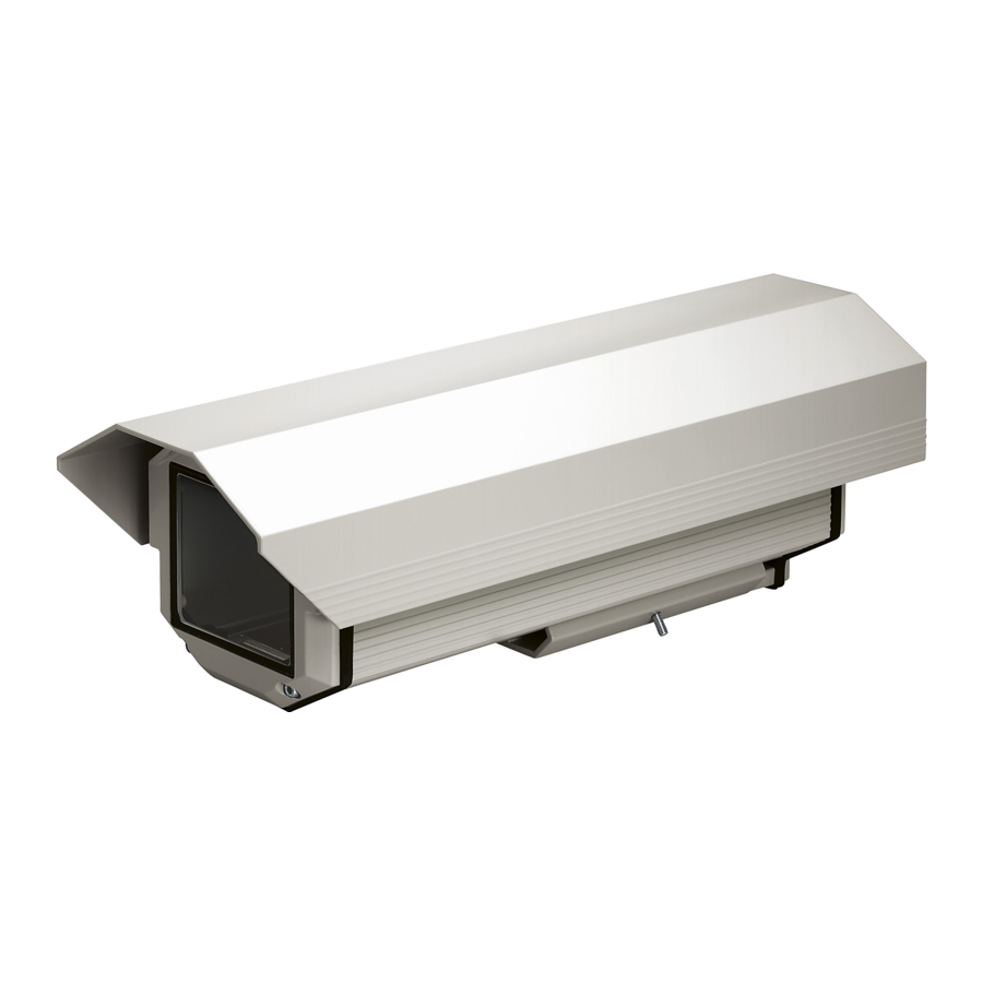
Middle-dimensions weatherproof housing
HEA

Publicité

Table des Matières
loading

Sommaire des Matières pour Videotec HEA26

  • Page 1 Middle-dimensions weatherproof housing English - Instructions manual Italiano - Manuale di istruzioni Français - Manuel d'instructions Deutsch - Bedienungslanleitung...
  • Page 3 Middle-dimensions weatherproof housing English - Instructions manual...
  • Page 4: Table Des Matières

    Contents ENGLISH 1 About this manual ......................3 1.1 Typographical conventions ..........................3 2 Notes on copyright and information on trademarks ..........3 3 Safety rules ........................3 4 Identification ........................ 3 4.1 Product description and type designation ....................3 4.2 Product markings ..............................
  • Page 5: About This Manual

    1  About this manual • The device must be installed only and exclusively by qualified technical personnel. Before installing and using this unit, please read this • Before any technical work on the appliance, manual carefully. Be sure to keep it handy for later disconnect the power supply.
  • Page 6: Preparing The Product For Use

    5  Preparing the product  6  Assembling and  for use installing Any change that is not expressly approved Only specialised personnel should be by the manufacturer will invalidate the allowed to assemble and install the device. guarantee. 6.1 Installation 5.1 Contents and unpacking 6.1.1 How to open the housing When the product is delivered, make sure that the To open the housing, unscrew the 2 screws (01) package is intact and that there are no signs that it...
  • Page 7: How To Install The Camera

    6.1.2 How to install the camera Fix the printed circuit on the slide’s pre-arranged side near the rear cover plate (Fig. 01, 03). This chapter describes how to install the camera into Connect the wires of the heating element to the the housing.
  • Page 8: 12Vdc Power Supply

    6.1.4.1 12Vdc power supply n the circuit there is also the possibility of drawing power supply for a camera. Fix the blower kit on the bottom, with the air flow towards the inside, by means of the relevant IN 24Vac OUT 24Vac screws supplied with the kit.
  • Page 9: How To Install The Camera Power Supply

    Carry out the connections of the circuit to the Fix the camera power supply circuit in the available external source of power. position of the internal slide in the bottom rear of the housing (03). The dustproof housings are pre-arranged for fixing possible ground connections to be carried out in compliance with the legislation in force.
  • Page 10: Maintaining And Cleaning

    Glass window (WxH): 86x 70mm (3.4x2.8in) 8  Disposal of waste  Internal usable area (WxH): 84x70mm (3.3x2.7in) materials Internal usable length without accessories HEA26 260mm (10.2in) This symbol mark and recycle system HEA30 300mm (11.8in) are applied only to EU countries and not...
  • Page 11: Technical Drawings

    10  Technical drawings The values are in millimeters. 260 / 300 331 / 371 377 / 420 Fig. 13...
  • Page 12 VIDEOTEC S.p.A. www.videotec.com Printed in Italy MNVCHEAA_0946_EN...
  • Page 13 Custodia stagna di medie dimensioni Italiano - Manuale di istruzioni...
  • Page 14 Sommario ITALIANO 1 Informazioni sul presente manuale ................3 1.1 Convenzioni tipografiche ............................ 3 2 Note sul copyright e informazioni sui marchi commerciali ........3 3 Norme di sicurezza ....................... 3 4 Identificazione ......................3 4.1 Descrizione e designazione del prodotto ..................... 3 4.2 Marcatura del prodotto ............................
  • Page 15: Informazioni Sul Presente Manuale

    1  Informazioni sul presente  • L'installazione e la manutenzione del dispositivo deve essere eseguita solo da personale tecnico manuale qualificato. • Prima di effettuare interventi tecnici Prima di installare e utilizzare questa unità, leggere sull'apparecchio togliere l'alimentazione elettrica. attentamente questo manuale. Conservare questo •...
  • Page 16: Preparazione Del Prodotto Per L'utilizzo

    5  Preparazione del  6  Assemblaggio e  prodotto per l'utilizzo installazione Qualsiasi cambiamento non espressamente L'assemblaggio e l'installazione vanno approvato dal costruttore fa decadere la eseguiti solo da personale specializzato. garanzia. 6.1 Installazione 5.1 Contenuto e disimballaggio 6.1.1 Apertura della custodia Alla consegna del prodotto verificare che l'imballo Per l’apertura della custodia, svitare le 2 viti (01) poste sia integro e non abbia segni evidenti di cadute o lateralmente a metà...
  • Page 17: Installazione Della Telecamera

    6.1.2 Installazione della telecamera Fissare il circuito stampato sulla predisposizione della slitta nei pressi del fondo posteriore (Fig. 01, 03). Questa sezione descrive come installare la Connettere i fili dell’elemento riscaldante al circuito telecamera all’interno della custodia. Si ricorda che sul morsetto indicato con HEATER.
  • Page 18: Alimentazione 12Vdc

    6.1.4.1 Alimentazione 12Vdc Nel circuito c’è anche la possibilità di prelevare l’alimentazione per una telecamera. Fissare il ventilatore sul fondo tramite le apposite viti in dotazione. Si ricorda che normalmente i fondi, IN 24Vac OUT 24Vac dedicati all’utilizzo con ventilatore, sono forniti con un foro aggiuntivo con relativo filtro per la presa dell’aria.
  • Page 19: Installazione Dell'alimentatore Per Telecamera

    Eseguire le connessioni del circuito alla fonte di Fissare il circuito dell’alimentatore sulla alimentazione esterna. predisposizione della slitta interna nei pressi del fondo posteriore (03). Le custodie del tipo antipolvere hanno la predisposizione per il fissaggio delle eventuali connessioni di terra da eseguire secondo le norme vigenti.
  • Page 20: Manutenzione E Pulizia

    Finestra in vetro (WxH): 86x70mm 8  Smaltimento dei rifiuti Dimensioni utili interne (WxH): 84x70mm Lunghezza utile interna senza accessori Questo simbolo e il sistema di riciclaggio HEA26 260mm sono validi solo nei paesi dell'EU e non trovano applicazione in altri paesi del HEA30 300mm mondo.
  • Page 21: Disegni Tecnici

    10  Disegni tecnici I valori espressi sono in millimetri. 260 / 300 331 / 371 377 / 420 Fig. 13...
  • Page 22 VIDEOTEC S.p.A. www.videotec.com Printed in Italy MNVCHEAA_0946_IT...
  • Page 23 Caisson étanche de dimensions moyennes Français - Manuel d'instructions...
  • Page 24 Sommaire FRANÇAIS 1 À propos de ce mode d’emploi ..................3 1.1 Conventions typographiques ..........................3 2 Notes sur le copyright et informations sur les marques de commerce ....3 3 Normes de securité ....................... 3 4 Identification ........................ 3 4.1 Description et désignation du produit ......................
  • Page 25: Propos De Ce Mode D'emploi

    1  À propos de ce mode  • L’installation et l’entretien du dispositif doivent être exclusivement être effectués par un personnel d’emploi technique qualifié. • Sectionner l’alimentation électrique avant toute Avant d’installer et d’utiliser cet appareil, veuillez intervention technique sur l’appareil. lire attentivement ce mode d’emploi. Conservez-le à •...
  • Page 26: Préparation Du Produit En Vue De L'utilisation

    5  Préparation du produit  6  Assemblage et  en vue de l’utilisation installation Toute modification non approuvée L’assemblage et l’installation doivent expressément par le fabricant entraînera exclusivement être effectués par un l’annulation de la garantie. personnel spécialisé. 5.1 Contenu et déballage 6.1 Installation Lors de la livraison du produit, vérifier que 6.1.1 Ouverture du caisson l’emballage est en bon état et l’absence de tout signe Pour ouvrir le caisson il faut dévisser les 2 vis (01)
  • Page 27: Installation De La Camera

    6.1.2 Installation de la camera Fixez le circuit imprimé sur l’emplacement du chariot situé près du fond postérieur (Fig. 01, 03). Cette section explique comment installer la caméra Connectez les fils de l’élément chauffant au circuit à l’intérieur du caisson. A noter que l’alimentation sur la borne marquée par HEATER (Fig.
  • Page 28: Alimentation 12Vdc

    6.1.4.1 Alimentation 12Vdc Le circuit permet également de prélever l’alimentation pour une caméra. Au moyen des vis fournies, fixez le ventilateur sur le fond, avec l’écoulement d’air vers l’intérieur. IN 24Vac OUT 24Vac A noter que les fonds, prévus pour l’emploi avec ventilateur, sont normalement livrés avec un trou supplémentaire équipé...
  • Page 29: Installation De L'alimentateur Pour Camera

    Effectuez les connexions du circuit à la source Fixer le circuit de l’alimentateur sur le chariot interne, d’alimentation externe (Fig. 10, 02). à l’endroit prévu à cet effet, qui se trouve dans le fond postérieur (03). Les caissons anti-poussière sont équipés d’un emplacement pour la fixation d’éventuelles connexions à...
  • Page 30: Entretien Et Nettoyage

    2 presse-étoupes M16 traitée. Fenêtre en verre (WxH): 86x70mm Surface intérieure utile (WxH): 84x70mm 8  Élimination des déchets Longueur intérieure utile sans accessoires HEA26 260mm Ce symbole et le système de recyclage ne sont appliqués que dans les pays UE et non HEA30 300mm dans les autres pays du monde.
  • Page 31: Dessins Techniques

    10  Dessins techniques Les valeurs sont entendues en millimètres. 260 / 300 331 / 371 377 / 420 Fig. 13...
  • Page 32 VIDEOTEC S.p.A. www.videotec.com Printed in Italy MNVCHEAA_0946_FR...
  • Page 33 Wasserdichtes mittelgroßes Gehäuse Deutsch - Bedienungslanleitung...
  • Page 34 Inhaltsverzeichnis DEUTSCH 1 Allgemeines ........................3 1.1 Schreibweisen ................................. 3 2 Anmerkungen zum Copyright und Informationen zu den Handelsmarken .... 3 3 Sicherheitsnormen ....................... 3 4 Identifizierung ......................3 4.1 Beschreibung und Bezeichnung des Produktes ..................3 4.2 Kennzeichnung des Produkts ..........................3 5 Vorbereitung des Produktes auf den Gebrauch ............
  • Page 35: Allgemeines

    1  Allgemeines • Die Installation und Wartung der Vorrichtung ist technischen Fachleuten vorbehalten. Lesen Sie bitte vor dem Installieren und dem • Vor technischen Eingriffen am Gerät muss die Verwenden dieses Gerätes die Bedienungsanleitung Stromversorgung unterbrochen werden. sorgfältig durch. Bewahren Sie sie zum späteren •...
  • Page 36: Vorbereitung Des Produktes Auf Den Gebrauch

    5  Vorbereitung des  6  Zusammenbau Und  Produktes auf den  Installation Gebrauch Zusammenbau und Installation sind Fachleuten vorbehalten. Jede vom Hersteller nicht ausdrücklich genehmigte Veränderung führt zum Verfall 6.1 Installation der Gewährleistungsrechte. 6.1.1 Öffnung des Gehäuses 5.1 Inhalt und Entfernen der Zum Öffnen des Gehäuses die an der Rückwand auf Verpackung halber Höhe seitlich angebrachten 2 Schrauben (01) lösen und den Körper (02) herausziehen.
  • Page 37: Installation Der Kamera

    6.1.2 Installation der Kamera Die gedruckte Schaltung an der auf dem Schlitten vorgesehenen Stelle in der Nähe der Rückwand In diesem Abschnitt wird beschrieben, wie die befestigen (Fig. 01, 03). Kamera im Inneren des Gehäuses installiert wird. Die Drähte des Heizelements an den Schaltkreis an Es wird daran erinnert, daß...
  • Page 38: Betriebsspannung 12Vdc

    6.1.4.1 Betriebsspannung 12Vdc Der Schaltkreis bietet auch die Möglichkeit, die Betriebsspannung für eine Kamera zu entnehmen. Den Lüfter mit den mitgelieferten Schrauben mit nach innen gerichtetem Luftfluß am Boden befestigen. IN 24Vac OUT 24Vac Normalerweise sind die Böden, die für den Einbau des Ventilators vorgesehen sind, mit einem zusätzlichen Loch für die Luftans-augung und dem zugehörigen Filter ausgestattet.
  • Page 39: Installation Der Netzteil Für Kamera

    Die Anschlüsse der Schaltung an die äußere Schaltung der Speiseleitung an der Auslegung der Versorgungsquelle durchführen (Fig. 10, 02). internen Führung am Rückgrund befestigen (03). Die staubdichten Gehäuse sind für die Befestigung der eventuellen Erdanschlüsse, die den geltenden Bestimmungen entsprechend auszuführen sind, vorbereitet.
  • Page 40: Wartung Und Reinigung

    8  Müllentsorgungsstellen Glasfenster (WxH): 86x70mm Innere Nutzabmessungen (WxH): 84x70mm Dieses Symbol und das entsprechende Innere Nutzlänge ohne Zubehör Recycling-System gelten nur für EULänder HEA26 260mm und finden in den anderen Ländern der HEA30 300mm Welt keine Anwendung. Innere Nutzlänge mit Zubehör...
  • Page 41: Technische Zeichnungen

    10  Technische Zeichnungen Maßangabe in Millimeter. 260 / 300 331 / 371 377 / 420 Fig. 13...
  • Page 42 VIDEOTEC S.p.A. www.videotec.com Printed in Italy MNVCHEAA_0946_DE...
  • Page 44 VIDEOTEC S.p.A. www.videotec.com Printed in Italy MNVCHEAA_0946...

Ce manuel est également adapté pour:

Hea30Hea26k1Hea30k1

Table des Matières