Publicité
Les langues disponibles
Les langues disponibles
Liens rapides
S p l i t - t y p e A i r- C o n d i t i o n e r
M X Z - 2 C 2 0 N A H Z 3
M X Z - 3 C 2 4 N A H Z 3
M X Z - 3 C 3 0 N A H Z 3
M X Z - 5 C 4 2 N A 3
I n s t a l l a t i o n M a n u a l
• This manual only describes the installation of outdoor unit.
When installing the indoor unit, refer to the installation manual of indoor unit.
Any structural alterations necessary for installation must comply w ith local build-
ing code requirements.
N o t i c e d ' i n s t a l l a t i o n
• Cette notice ne décrit que l'installation de l'appareil extérieur.
Lors de l'installation de l'appareil intérieur, consultez la notice d'installation de cet
appareil.
Toute altération structurelle requise pour l'installation doit être conforme aux exi-
gences du code du bâtiment local.
M a n u a l d e i n s t a l a c i ó n
• En este manual só lo se describe la instalació n de la unidad exterior.
Para instalar la unidad interior, consulte el manual de instalació n de dicha unidad.
Cualquier modificaci n estructural necesaria para llevar a cabo la instalaci n de-
ber cumplir las normas de edificaci n locales.
For INSTALLER
Destinée à l'INSTALLATEUR
Para el INSTALADOR
E n g l i s h
F ra n ç a i s
E s p a ñ o l
Publicité

Manuels Connexes pour Mitsubishi Electric MXZ-2C20NAHZ3


Sommaire des Matières pour Mitsubishi Electric MXZ-2C20NAHZ3
- Page 1 S p l i t - t y p e A i r- C o n d i t i o n e r M X Z - 2 C 2 0 N A H Z 3 M X Z - 3 C 2 4 N A H Z 3 M X Z - 3 C 3 0 N A H Z 3 M X Z - 5 C 4 2 N A 3 For INSTALLER...
-
Page 2: Table Des Matières
Refrigerant Rated Voltage Frequency for multi-system difference for multi system adjustment A *7 MXZ-2C20NAHZ3 82 ft. (25 m) / 164 ft. (50 m) 25 / 50 MXZ-3C24NAHZ3 1.08 oz each 5 ft. 208 / 230 V 60 Hz 82 ft. (25 m) / 230 ft. (70 m) 49 ft. - Page 3 1 - 3 . S E L E C T I N G O P T I O N A L D I F F E R E N T - D I A M E T E R J O I N T S If the diameter of connection pipe does not match the port size of outdoor unit, use optional different-diameter joints according to the follow ing table.
-
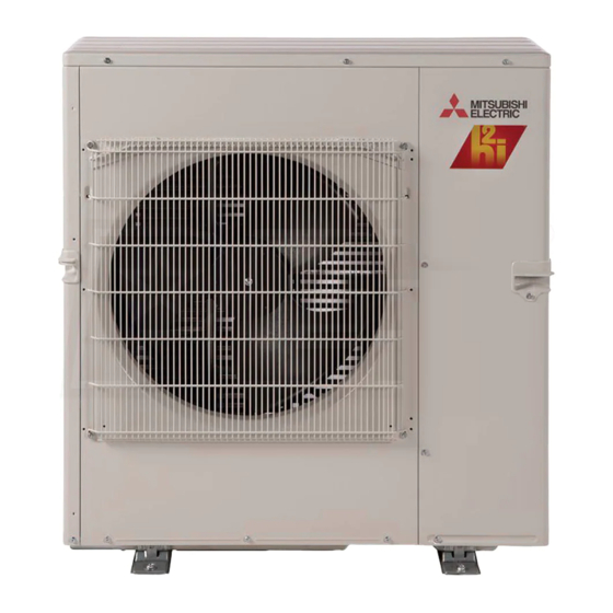
Page 4: Outdoor Unit Installation
• Refer to the figure in the right for concrete foundation. • In case of MXZ-2C20NAHZ3, MXZ-3C24/30NAHZ3, do not use the drain socket and the drain caps. • In case of MXZ-5C42NA3, do not use the drain socket and the drain caps in the cold region. Drain may freeze and it makes the fan stop. - Page 5 • Be sure to use special circuits for room air conditioner. ELECTRICAL SPECIFICATIONS • Wiring w ork should be based on applicable technical standards. OUTDOOR UNIT MXZ-2C20NAHZ3 MXZ-3C24NAHZ3 MXZ-3C30NAHZ3 MXZ-5C42NA3 • Wiring connections should be made follow ing the diagram.
-
Page 6: Flaring Work And Pipe Connection
3 . F L A R I N G W O R K A N D P I P E C O N N E C T I O N 3 - 1 . F L A R I N G W O R K 1) Cut the copper pipe correctly w ith pipe cutter. -
Page 7: Purging Procedures, Leak Test, And Test Run
4 . P U R G I N G P R O C E D U R E S , L E A K T E S T , A N D T E S T R U N 4 - 1 . P U R G I N G P R O C E D U R E S A N D L E A K T E S T Compound pressure 1) Remove service port cap of stop valve on the side of the outdoor unit gas pipe. -
Page 8: Pumping Down
4 - 3 . T E S T R U N Be sure to also check the follow ing. The outdoor unit is not faulty. When the outdoor unit fails, LED outdoor unit control panel blinks. L ED Both the gas and liquid stop valves are completely open. •... - Page 9 / pour système à nominale hauteur max. A *7 plusieurs appareils plusieurs appareils MXZ-2C20NAHZ3 82 pi. (25 m) / 164 pi. (50 m) 25 / 50 MXZ-3C24NAHZ3 1,08 once tous les 5 pi. 208 / 230 V 60 Hz 82 pi.
- Page 10 1 - 3 . S É L E C T I O N D E J O I N T S D E D I A M È T R E D I F F É R E N T E N O P T I O N Si le diamètre des tuyaux de connexion ne correspond pas au diamètre de passage de l’appareil extérieur, utiliser des joints de diamètre différent en option selon le tableau suivant.
- Page 11 • Se référer à la figure ci-à droite pour les fondations. • Pour les modèles MXZ-2C20NAHZ3 et MXZ-3C24/30NAHZ3, ne pas utiliser la douille d’évacuation ni les bouchons d’évacuation. • Pour le modèle MXZ-5C42NA3, ne pas utiliser la douille d’évacuation ni les bouchons d’évacuation en région froide. Le liquide vidangé pourrait geler et provoquer l’arrêt du ventilateur.
- Page 12 2 - 2 . B R A N C H E M E N T D E S C Â B L E S D E L ’ A P P A R E I L E X T É R I E U R •...
- Page 13 3 . T R A V A U X D ’ E V A S E M E N T E T R A C C O R D E M E N T D E S T U Y A U X 3 - 1 .
- Page 14 4. P R O C E D U R E S D E P U R G E , T E S T D E C O N T R O L E D E S F U I T E S E T E S S A I D E F O N C T I O N N E M E N T 4-1.
- Page 15 4-3. ESSAI S’assurer de vérifier les points suivants. L’appareil extérieur n’est pas défectueux. Lorsque l’appareil extérieur connaît une erreur, un L ED voyant DEL clignote sur le panneau de commande de l’appareil extérieur. Les vannes de gaz et d’arrêt du liquide sont toutes les deux complètement ouvertes. •...
- Page 16 H e rra m i e n t a s n e c e s a ri a s p a ra l a i n s t a l a c i ó n Í N D I C E Abocardador para R410A Destornillador Phillips Nivel...
- Page 17 1 - 3 . S E L E C C I Ó N D E L A S J U N T A S P A R A D I S T I N T O S D I Á M E T R O S O P C I O N A L E S Si el diá...
- Page 18 1 - 5 . D I A G R A M A D E I N S T A L A C I Ó N Después de la prueba de fugas, aplique C O M P O N E N T E S Q U E D E B E R Á A D Q U I R I R material aislante de modo que no queden huecos.
- Page 19 2 - 2 . C A B L E S D E C O N E X I Ó N P A R A L A U N I D A D E X T E R I O R •...
- Page 20 3 . T R A B A J O S D E A B O C A R D A D O Y C O N E X I Ó N D E T U B E R Í A S 3 - 1 .
- Page 21 4. PROCEDIMIENTOS DE PURGADO, PRUE A DE FUGAS FUNCIONAMIENTO DE PRUE A 4-1. PROCEDIMIENTO DE PURGADO PRUE A DE FUGAS 1) Retire la tapa de la abertura de servicio de la vá lvula de retenció n situada en Indicador de presió n compuesto (para R410A) el lado de la tuber a de gas de la unidad exterior.
- Page 22 4-3. COMPRO ACI N DE FUNCIONAMIENTO Aseg rese, asimismo, de comprobar lo siguiente: La unidad exterior no está defectuosa. Cuando se produce un error en la unidad exterior, los indicadores luminosos del panel de control de la unidad exterior parpadean. L ED Indicador Las v lvulas de retenci n de gas y l quido permanecen completamente abiertas.
- Page 24 HEAD OFFICE: TOKYO BUILDING, 2-7-3, MARUNOUCHI, CHIYODA-KU, TOKYO 100-8310, JAPAN VG79N001H01...