Publicité

Les langues disponibles
  • FR

Les langues disponibles

  • FRANÇAIS, page 39

Liens rapides

Kurzbeschreibung
Ventilinsel Typ
CPV-... mit
AS-interface Typ
CPV..-GE-ASI-4E4A-...
Notice simplifiee
Terminal de
distributeurs
type CPV-... avec
interface AS type
CPV..-GE-ASI-4E4A-...
Brief description
Valve terminal type
CPV-... with
AS interface type
CPV..-GE-ASI-4E4A-...
Breve descrizione
Unità di valvole
tipo CPV-... con
interfaccia AS
CPV..-GE-ASI-4E4A-...
Breve descripción
Terminal de válvulas
tipo CPV-... con
Interface tipo AS
CPV..-GE-ASI-4E4A-...
Beskrivning
Ventilterminal
typ CPV-... med
AS-interface
typ
CPV..-GE-ASI-4E4A-...
9807a

Publicité

Table des Matières
loading

Sommaire des Matières pour Festo CPV-GE-ASI-4E4A Serie

  • Page 1 Brief description Breve descripción Kurzbeschreibung Valve terminal type Terminal de válvulas Ventilinsel Typ CPV-... mit CPV-... with tipo CPV-... con AS-interface Typ AS interface type Interface tipo AS CPV..-GE-ASI-4E4A-... CPV..-GE-ASI-4E4A-... CPV..-GE-ASI-4E4A-... Notice simplifiee Breve descrizione Beskrivning Terminal de Unità di valvole Ventilterminal tipo CPV-...
  • Page 2 Svenska ........63 © (Festo AG & Co., D-73726 Esslingen, 1998) 9807a...
  • Page 3 CPV..-GE-ASI-4E4A-... Benutzerhinweise Die AS-i-Ventilinsel Typ 10 ist ausschließlich zur Steuerung von pneumatischen Aktuatoren bestimmt und nur für den Einsatz in Bussystemen gemäß der AS-i-Spezifikation geeignet. Beim An- schluß handelsüblicher Zusatzkomponenten, wie Sensoren und Aktoren sind die angegebenen Grenzwerte für Drücke, Tempe- raturen, elektrische Daten, Momente usw.
  • Page 4 CPV..-GE-ASI-4E4A-... Anschluß- und Anzeigeelemente AS-i-Busanschluß LED-Zustandsanzeige LED-Zustandsanzeige für Eingänge (grün) für Ventile (gelb) Sensoranschlüsse (PNP) Lastspannungsanschluß Anschluß Funktionserde für Ventile *) Typenschild (ID- und IO-Code) BUS-LED 1 (grün) Beschriftungsfeld für AS-i-Adresse BUS-LED 2 (rot) *) Nur bei Typ CPV..-GE-ASI-4E4A-Z: Ventile bei NOT-AUS abschaltbbar, keine Spannungsversorgung der Ventile über AS-i-Bus BUS-LED 1 BUS-LED 2...
  • Page 5 CPV..-GE-ASI-4E4A-... Installationshinweise 3.1 Zuweisen der AS-i-Adresse Empfehlung: Verwenden Festo-Adressiergerät ASI-PRG-ADR Bestell-Nr. 18959 mit Adapterkabel Bestell-Nr. 18960 (oder Siemens PSG). Vor dem Anschließen eines AS-i-Slaves an den Bus: Weisen Sie jedem AS-i-Slave eine noch nicht belegte AS-i-Adresse zu. Stellen Sie Ihre gewünschte Adresse mit dem AS-i-Adressierge- rät ein.
  • Page 6 CPV..-GE-ASI-4E4A-... 3.2 Sensoren anschließen (PNP-Eingänge) Verwenden Sie zum Anschluß von Sensoren Kabel vom Typ KM8-M8-GSGD-... und Stecker mit Überwurfmutter, Gewinde M8x1. Fixieren Sie die Stecker mit Hilfe der Überwurfmutter, um unbe- absichtigtes Lösen z. B. durch Erschütterungen zu vermeiden. Verschließen Sie ungenutzte Sensoranschlüsse mit den mitge- lieferten Schutzkappen.
  • Page 7 CPV..-GE-ASI-4E4A-... 3.3 Festo-Installationszubehör Empfehlung: Verwenden Sie für den Anschluß der Ventilinseln Typ 10 die Festo-Kabeldosen ASI-SD-FK, Bestell-Nr. 18785. Sie erreichen damit Schutzart IP65. Gehen Sie wie folgt vor: 1. Kabeldose anschließen gemäß separater Kurzbeschreibung. 2. AS-i-Kabel zugfrei ausrichten. 3. Kabeldose aufstecken und festschrauben.
  • Page 8 CPV..-GE-ASI-4E4A-... 3.4 AS-i-Bus und Lastspannung anschließen HINWEIS: Über den AS-i-Bus wird die Sensorversorgung für die Ein- gänge bereit gestellt. Eine Spannungsversorgung der Ausgänge über den AS-i- Bus ist nur bei Typ CPV...-GE-ASI-4E4A möglich. Typ CPV...-...-Z ist immer getrennt über den Lastspannungs- anschluß...
  • Page 9 CPV..-GE-ASI-4E4A-... Pin 2 = AS-i + (braun) Pin 2 = + 24V *) Pin 1 = AS-i - (hellblau) Pin 1 = 0 V *) *) Nur bei CPV...-GE-ASI-4E4A-Z Festo-Zubehör: AS-i-Kombinetzteil ASI-CNT-115/230VAC, Bestell-Nr. 18949 AS-i-Buskabel (gelb) KASI-1.5-Y-100, Bestell-Nr. 18940 Zusatzversorgungs- KASI-1.5-Z-100,...
  • Page 10 CPV..-GE-ASI-4E4A-... 3.5 Anschlußbeispiel Ventilinsel Typ 10 ohne/mit NOT-AUS AS-i-Master NOT-AUS-Relais Festo-Kombinetzteil 9807a...
  • Page 11 CPV..-GE-ASI-4E4A-... 3.6 Adreßbelegung der Magnetspulen (Draufsicht) Insel mit 2 bistabilen Insel mit 4 Insel mit 1 bistab. und Ventilen monostabilen Ventilen 2 monostab. Ventilen Adressbelegung der Magnetspulen 9807a...
  • Page 12 CPV..-GE-ASI-4E4A-... 3.7 Umbau der CP-Ventilinsel Die CP-Ventilinsel kann mit bistabilen und/oder mit monostabi- len Ventilen bestückt werden. Bei Umbau ist die neue Ventilin- selkonfiguration an einem DIP-Schalter auf der Unterseite der Anschlußplatte einzustellen. Hinweise zum Lösen der An- schlußplatte finden Sie in der Pneumatik-Beschreibung. DIP-Schalter auf der Unterseite der Anschlußplatte Insel mit 2 bistabilen Insel mit 4 mono-...
  • Page 13: Technische Daten

    CPV..-GE-ASI-4E4A-... Technische Daten CPV...-GE-ASI-4E4A... M8 Schutzart (nach DIN 40050) IP 65 (komplett montiert) Temperatur: – bei Betrieb - 5° bis + 50° C – bei Lagerung/Transport - 20° bis + 70° C Elektromagnetische Verträglichkeit – Störaussendung – geprüft nach EN 55011, Grenzwertklasse B –...
  • Page 14 CPV..-GE-ASI-4E4A-... CPV...-GE-ASI-4E4A... M8 Lastspannungsanschluß (nur Typ ...-4E4A-Z) – Nennwert (verpolungssicher) DC 20,4 V ... 26,4 V – Restwelligkeit 4 Vss – Stromaufnahme für 4 Ventile (bei 24 V) CPV10-... CPV14-... – beim Einschalten 108 mA 176 mA – nach Stromabsenkung (stationär) 42 mA 72 mA Ventile...
  • Page 15 CPV..-GE-ASI-4E4A-... User instructions The AS-i valve terminal type 10 is designed exclusively for con- trolling pneumatic actuators and may only be used in bus systems in accordance with the AS-i specifications. The speci- fied limit values for pressures, temperatures, electrical data, moments, etc.
  • Page 16 CPV..-GE-ASI-4E4A-... Connecting and display elements AS-i bus connection LED status display for LED status display for inputs (green) valves (yellow) Sensor connections (PNP) Load voltage Functional earth connection connection for valves *) Type plate (ID and IO codes) BUS LED 1 (green) Inscription field for AS-i address BUS LED 2 (red) *) Only with type CPV..-GE-ASI-4E4A-Z: Valves can be switched off during...
  • Page 17: Installation Instructions

    CPV..-GE-ASI-4E4A-... Installation instructions 3.1 Assigning the AS-i address We recommend that you use the Festo addresser ASI-PRG- ADR (part no. 18959) with adapter cable (part no. 18960 or Siemens PSG). Before connecting an AS-i slave to the bus, you should assign a non-reserved AS-i address to each AS-i slave.
  • Page 18 CPV..-GE-ASI-4E4A-... 3.2 Connecting sensors (PNP inputs) Use cable type KM8-M8-GSGD-... and plugs with union nuts, thread M8x1, for connecting sensors. Fasten the plugs with the aid of the union nuts in order to pre- vent unintentional loosening (e.g. due to vibration). Seal unused sensor connections with the protective caps supplied.
  • Page 19 – An open-ended cable should be fitted with a Festo cable cap type ASI-KK-FK (part no. 18787) or with a cable bushing type ASI-KT-FK (part no. 165 593). You thereby avoid leakage currents and comply with protection class IP65.
  • Page 20 CPV..-GE-ASI-4E4A-... 3.4 Connecting the AS-i bus and load voltages PLEASE NOTE The sensor supply for the inputs is provided via the AS-i bus. Voltage suppply of the outputs via the AS-i bus is only possible with type CPV...-GE-ASI-4E4A. Type CPV...-...-Z must always be supplied with 24 V via the load voltage connection.
  • Page 21 Pin 2 = AS-i + (brown) Pin 2 = + 24V *) Pin 1 = AS-i - (light blue) Pin 1 = 0 V *) *) Only with CPV...-GE-ASI-4E4A-Z Festo accessories: AS-i combi power unit ASI-CNT-115/230V AC, part no. 18949 AS-i bus cable (yellow) KASI-1.5-Y-100,...
  • Page 22 CPV..-GE-ASI-4E4A-... 3.5 Example of connections for valve terminal type 10 with/without EMERGENCY STOP AS-i master EMERGENCY STOP relay Festo combi power unit 9807a...
  • Page 23 CPV..-GE-ASI-4E4A-... 3.6 Address assignment of the solenoid coils (top view) Terminal with two Terminal with 4 single- Terminal with 1 double- double-solenoid valves solenoid valves solenoid and 2 single- solenoid valves Address assignment of the solenoid coils 9807a...
  • Page 24 CPV..-GE-ASI-4E4A-... 3.7 Conversion of the CP valve terminal The CP valve terminal can be fitted with double-solenoid valves and/or with single-solenoid valves. If the valve terminal is con- verted, the new configuration must be set by means of a DIP switch on the bottom of the sub-base.
  • Page 25: Technical Specifications

    CPV..-GE-ASI-4E4A-... Technical specifications Type CPV...-GE-ASI-4E4A... M8 Protection class (as per DIN 40050) IP 65 (fully mounted) Temperature: – operation - 5° bis + 50° C – storage/transport - 20° bis + 70° C Electromagnetic compatibility – interference emission – tested as per EN 55011, limit value class B –...
  • Page 26 CPV..-GE-ASI-4E4A-... Type CPV...-GE-ASI-4E4A... M8 Load voltage connection (only type ...-4E4A-Z) – rated value 20.4 V ... 26.4 V DC (protected against incorrect polarity) – residual ripple 4 Vpp – Current consumption for 4 valves (at 24 V) CPV10-... CPV14-... – when switching on 108 mA 176 mA –...
  • Page 27 CPV..-GE-ASI-4E4A-... Instrucciones para el usuario El terminal de válvulas AS-i tipo 10 está diseñado exclusiva- mente para el control de actuadores neumáticos y sólo puede ser utilizado en sistemas de bus que cumplan con las especifi- caciones AS-i. Cuando se conecten componentes adicionales disponibles en el comercio, tales como sensores y actuadores, deberán observarse los valores límite especificados para pre- siones, temperaturas, datos eléctricos, momentos, etc.
  • Page 28: Elementos De Conexión E Indicación

    CPV..-GE-ASI-4E4A-... Elementos de conexión e indicación Conexión al bus AS-i LED indicador de LED indicador de estado estado para válvulas para inputs (verde) (amarillo) Conexiones para sensores (PNP) Conexión de la tensión Conexión de tierra para válvulas *) Placa del tipo (códigos ID e IO ) BUS LED 1 (verde) Campo de inscripción para direcciones AS-i BUS LED 2 (rojo)
  • Page 29 CPV..-GE-ASI-4E4A-... Instrucciones de instalación 3.1 Asignación de direcciones AS-i Recomendamos la utilización del direccionador Festo ASI-PRG- ADR (Nº de artículo 18959) con el cable de adaptación (Nº de artículo 18960 o el PSG de Siemens). Antes de conectar un slave AS-i al bus, debe reservar una di- rección AS-i no asignada a cada slave AS-i.
  • Page 30 CPV..-GE-ASI-4E4A-... 3.2 Conexión de sensores (Inputs PNP) Para conectar los sensores, utilice el cable tipo KM8-M8- GSGD-... y clavijas con tuercas de unión, rosca M8x1. Apriete las clavijas con la ayuda de las tuercas de unión para evitar que se aflojen accidentalmente (p. ej. por las vibracio- nes).
  • Page 31 CPV..-GE-ASI-4E4A-... 3.3 Accesorios de instalación Festo Le recomendamos que utilice los zócalos para cable Festo ASI- SD-FK (nº de artículo 18785) para la conexión de terminales de válvulas del tipo 10. Con ello se cumplirá el grado de protec- ción IP65.
  • Page 32 CPV..-GE-ASI-4E4A-... 3.4 Conexión de las tensiones de carga y del bus AS-i POR FAVOR, OBSERVAR: La alimentación a los sensores para las entradas es suminis- trada a través del bus AS-i. La alimentación de tensión a las salidas a través del bus AS- i sólo es posible con el tipo CPV...-GE-ASI-4E4A.
  • Page 33 Pin 2 = AS-i + (marrón) Pin 2 = + 24V *) Pin 1 = AS-i - (azul claro) Pin 1 = 0 V *) *) Sólo con CPV...-GE-ASI-4E4A-Z Accesorios Festo: Fuente de alimentación AS-i combi ASI-CNT-115/230V AC, Nº art. 18949 Cable del bus AS-i (amarillo) KASI-1.5-Y-100,...
  • Page 34 CPV..-GE-ASI-4E4A-... 3.5 Ejemplo de conexiones para el terminal de válvulas tipo 10 con/sin PARO DE EMERGENCIA Master AS-i Relé de PARO DE Fuente de alimentación EMERGENCIA Festo combi 9807a...
  • Page 35 CPV..-GE-ASI-4E4A-... 3.6 Asignación de direcciones a las bobinas de electroválvulas (vista superior) Terminal con Terminal con Terminal con 2 electroválvulas dobles 4 electroválvulas 1 electroválvula doble simples y 2 de simples Asignación de direcciones de las bobinas de electroválvulas 9807a...
  • Page 36 CPV..-GE-ASI-4E4A-... 3.7 Conversión del terminal de válvulas CP El terminal de válvulas CP puede equiparse con electroválvulas de doble o de simple bobina. Si el terminal se convierte poste- riormente, debe establecerse la nueva configuración por medio del interruptor DIP en el fondo de la placa base. En el manual de la parte neumática hallará...
  • Page 37: Especificaciones Técnicas

    CPV..-GE-ASI-4E4A-... Especificaciones técnicas Tipo CPV...-GE-ASI-4E4A... M8 Clase de protección (según DIN 40050) IP 65 (completamente montado) Temperatura: – funcionamiento - 5° bis + 50° C – almacenaje/transporte - 20° bis + 70° C Compatibilidad electromagnética – emisión de interferencias – verificado según EN 55011, valor límite clase B –...
  • Page 38 CPV..-GE-ASI-4E4A-... Tipo CPV...-GE-ASI-4E4A... M8 Conexión de la tensión de carga (sólo Tipo ...-4E4A-Z) – valor nominal (protegido contra DC 20,4 V ... 26,4 V polaridad incorrecta) – rizado residual 4 Vss – Consumo de corriente para 4 válvulas (a 24 V) CPV10-...
  • Page 39 CPV..-GE-ASI-4E4A-... Instructions d’utilisation Le terminal de distributeurs AS-i type 10 est exclusivement des- tiné à la commande d’actionneurs pneumatiques sur le bus ré- pondant aux spécifications AS-i. Lors de la connexion de com- posants courants du commerce, comme des capteurs et des actionneurs, respecter impérativement les valeurs limites de pressions, températures, caractéristiques électriques, couples, etc.
  • Page 40: Eléments De Signalisation Et De Raccordement

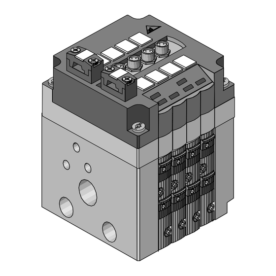
    CPV..-GE-ASI-4E4A-... Eléments de signalisation et de raccordement Connecteur du bus AS-i LED-témoins d’état des LED-témoins d’état des entrées (vert) distributeurs (jaunes) Connecteurs pour capteurs (PNP) Connecteurs Borne de terre d’alimentation pour Plaque signalétique (codes ID et IO) distributeurs *) Zone de repérage de l’adresse AS-i LED BUS 1 (verte) LED BUS 2 (rouge) *) Uniquement pour le type CPV..-GE-ASI-4E4A-Z : Distributeurs pouvant être...
  • Page 41: Attribution Des Adresses As-I

    Instructions d’installation 3.1 Attribution des adresses AS-i Recommandation : utiliser la console d’adressage Festo ASI-PRG-ADR réf. 18959 avec le câble d’adaptation de réf. 18960 (ou Siemens PSG). Avant de connecter un esclave AS-i sur le bus, lui attribuer une adresse AS-i non encore affectée. Spécifier l’adresse choisie sur la console d’adressage AS-i.
  • Page 42: Connexion De Capteurs (Entrées Pnp)

    CPV..-GE-ASI-4E4A-... 3.2 Connexion de capteurs (entrées PNP) Effectuer la connexion des capteurs à l’aide de câbles du type KM8-M8-GSGD-... et de connecteurs munis d’écrous-raccords, de filetage M8x1. Fixer le connecteur à l’aide de l’écrou-raccord, pour éviter son desserrage intempestif sous l’effet des vibrations. Obturer les connecteurs non utilisés à...
  • Page 43: Accessoires D'installation Festo

    CPV..-GE-ASI-4E4A-... 3.3 Accessoires d’installation Festo Recommandation : effectuer la connexion des terminaux de dis- tributeurs type 10 à l’aide de connecteurs Festo ASI-SD-FK, de réf. 18785. L’indice de protection IP 65 est ainsi garanti. Procéder de la manière suivante : 1.
  • Page 44: Connexion Du Bus As-I Et De L'alimentation Des Actionneurs

    CPV..-GE-ASI-4E4A-... 3.4 Connexion du bus AS-i et de l’alimentation des actionneurs REMARQUE : Le bus AS-i permet l’alimentation des capteurs au niveau des entrées. Une alimentation des sorties par le bus AS-i est possible uni- quement avec le type CPV...-GE-ASI-4E4A. Le type CPV...-...-Z doit toujours être alimenté...
  • Page 45 Broche 2 = AS-i + (marron) Broche 2 = + 24V *) Broche 1 = AS-i - (bleu clair) Broche 1 = 0 V *) *) Uniquement pour CPV..-GE-ASI-4E4A-Z Accessoires Festo : Bloc d’alimentation combiné AS-i ASI-CNT-115/230VAC, Réf. 18949 Câble de bus AS-i (jaune) KASI-1.5-Y-100, Réf.
  • Page 46: Exemple De Connexion D'un Terminal De Distributeurs

    CPV..-GE-ASI-4E4A-... 3.5 Exemple de connexion d’un terminal de distributeurs type 10 sans/avec ARRET D’URGENCE Maître AS-i Relais d’ARRET Bloc d’alimentation combiné D’URGENCE Festo 9807a...
  • Page 47: Affectation Des Adresses Des Bobines De Pilotage (Vue De Dessus)

    CPV..-GE-ASI-4E4A-... 3.6 Affectation des adresses des bobines de pilotage (vue de dessus) Terminal avec Terminal avec Terminal avec 2 distributeurs 4 distributeurs 1 distr. bistable et bistables monostables 2 distr. monostables Affectation des adresses des bobines de pilotage 9807a...
  • Page 48: Transformation D'un Terminal De Distributeurs Cp

    CPV..-GE-ASI-4E4A-... 3.7 Transformation d’un terminal de distributeurs CP Un terminal CP peut être équipé de distributeurs bistables et/ou monostables. En cas de transformation, le nouvel équipement du terminal doit être spécifié à l’aide des commutateurs DIP situés sur le dessous de la plaque de connexion. Le manuel Pneumatique fournit les instructions nécessaires pour décrocher la plaque de connexion.
  • Page 49: Caractéristiques Techniques

    CPV..-GE-ASI-4E4A-... Caractéristiques techniques Type CPV...-GE-ASI-4E4A... M8 Indice de protection (selon DIN 40050) IP 65 (montage terminé) Température : – de service - 5° à + 50° C – de stockage/transport - 20° à + 70° C Compatibilité électromagnétique – Emission de perturbations –...
  • Page 50 CPV..-GE-ASI-4E4A-... Type CPV...-GE-ASI-4E4A... M8 Alimentation des actionneurs (uniquement type ...-4E4A-Z) – Tension nominale (protégé DC 20,4 V ... 26,4 V contre l’inversion de polarité) – Ondulation résiduelle 4 Vss – Consommation de courant de 4 distributeurs (pour 24 V) CPV10-... CPV14-... –...
  • Page 51: Indicazioni Per L'utilizzatore

    CPV..-GE-ASI-4E4A-... Indicazioni per l’utilizzatore Le unità di valvole AS-i tipo 10 sono destinate esclusivamente all’azionamento degli attuatori pneumatici all’interno di sistemi bus secondo le specifiche AS-i. Per il collegamento dei compo- nenti commerciali, quali i sensori e gli attuatori, si devono ri- spettare i limiti di pressione, temperatura, parametri elettrici, coppie ecc.
  • Page 52 CPV..-GE-ASI-4E4A-... Elementi di collegamento e segnalazione Connettore bus AS-i LED segnalazione LED segnalazione stato ingressi (verde) stato valvole (giallo) Connettore sensori (PNP) Connettore tensione di Connettore di terra carico valvole *) Targhetta di identificazione (codici ID e IO) LED di bus 1 (verde) Targhetta di identificazione per indirizzo AS-i LED di bus 2 (rosso) *) Solo per il tipo CPV..-GE-ASI-4E4A-Z: possibilità...
  • Page 53: Indicazioni Per L'installazione

    CPV..-GE-ASI-4E4A-... Indicazioni per l’installazione 3.1 Assegnazione dell’indirizzo AS-i Si consiglia di utilizzare l’unità di indirizzamento Festo ASI-PRG-ADR, cod. ord. 18959, completa del relativo cavo adattatore, cod. ord. 18960 (in alternativa utilizzare Siemens PSG). Prima di collegare uno Slave AS-i al sistema bus, è opportuno associarlo a un indirizzo AS-i non ancora occupato, impostando con l’unità...
  • Page 54 CPV..-GE-ASI-4E4A-... 3.2 Collegamento dei sensori (ingressi PNP) Per il collegamento dei sensori, utilizzare cavi di tipo KM8-M8- GSGD-... e connettori maschio con ghiera (filetto M8x1). Per il fissaggio dei connettori utilizzare la ghiera, in modo da impedire l’allentamento accidentale a causa ad es. delle vibra- zioni.
  • Page 55 CPV..-GE-ASI-4E4A-... 3.3 Accessori per l’installazione Festo Per il collegamento delle unità di valvole tipo 10, si raccomanda di utilizzare i connettori Festo ASI-SD-FK (cod. ord. 18785). Solo questi componenti possono infatti garantire il grado di pro- tezione IP 65. Procedere nel seguente modo: 1.
  • Page 56 CPV..-GE-ASI-4E4A-... 3.4 Collegamento del bus AS-i/tensione di carico NOTA: I sensori degli ingressi vengono alimentati attraverso il bus AS-i. E’ possibile predisporre l’alimentazione di tensione alle usci- te attraverso il bus AS-i solamente nell’unità di valvole tipo CPV...-GE-ASI-4E4A. Per l’unità di valvole tipo CPV...-...-Z si deve prevedere sem- pre un’alimentazione separata a 24 V attraverso il connetto- re della tensione di carico.
  • Page 57 Pin 2 = AS-i + (marrone) Pin 2 = + 24 V *) Pin 1 = AS-i - (azzurro) Pin 1 = 0 V *) *) Solo per CPV...-GE-ASI-4E4A-Z Accessori Festo: Alimentatore Combi AS-i ASI-CNT-115/230VAC, cod. ord. 18949 Cavo bus AS-i (giallo) KASI-1.5-Y-100, cod.
  • Page 58 CPV..-GE-ASI-4E4A-... 3.5 Esempio di collegamento dell’unità di valvole tipo 10 ohne/con circuito di emergenza Master AS-i Relè di emergenza Alimentatore Combi Festo 9807a...
  • Page 59 CPV..-GE-ASI-4E4A-... 3.6 Occupazione degli indirizzi dei solenoidi (vista dall’alto) Unità con Unità con Unità con 2 valvole bistabili 4 valvole monostabili 1 valvola bistabile e 2 valvole monostabili Occupazione degli indirizzi dei solenoidi 9807a...
  • Page 60 CPV..-GE-ASI-4E4A-... 3.7 Modifica delle unità di valvole CP Le unità di valvole CP possono essere equipaggiate con valvole bistabili e/o monostabili. In caso di modifica della composizione dell’unità di valvole è necessario reimpostarne anche la configu- razione nel dip-switch posto nel lato inferiore della sottobase. Le istruzioni per lo smontaggio della sottobase sono contenute nella descrizione della pneumatica.
  • Page 61: Dati Tecnici

    CPV..-GE-ASI-4E4A-... Dati tecnici Tipo CPV...-GE-ASI-4E4A... M8 Grado di protezione (a norme DIN 40050) IP 65 (compl. assemblata) Temperatura: – di esercizio - 5° bis + 50° C – di stoccaggio/trasporto - 20° bis + 70° C Compatibilità elettromagnetica – emissione di interferenze –...
  • Page 62 CPV..-GE-ASI-4E4A-... Tipo CPV...-GE-ASI-4E4A... M8 Connettore della tensione di carico (solo tipo ...-4E4A-Z) – valore nominale (a prova di DC 20,4 V ... 26,4 V inversione di polarità) – ondulazione residua (Ripple) 4 Vss – assorbimento elettrico per 4 valvole (a 24 V) CPV10-...
  • Page 63 CPV..-GE-ASI-4E4A-... Anvisningar AS-i ventilterminal typ 10 är enbart avsedd för styrning av pneu- matiska arbetselement och enbart för användning i bussystem med AS-interface. Vid anslutning av på marknaden förekom- mande tillsatskomponenter såsom givare och aktorer, skall an- givna gränsvärden för tryck, temperaturer, elektriska data, mo- ment etc respekteras.
  • Page 64: Anslutnings- Och Indikeringselement

    CPV..-GE-ASI-4E4A-... Anslutnings- och indikeringselement AS-i bussanslutning LED-statusindikering för LED-statusindikering för ingångar (grön) ventiler (gul) Givaranslutningar (PNP) Strömförsörjning till Anslutning funktionsjord utgångar för ventilerna Typskylt (ID- och IO-kod) BUSS-LED 1 (grön) Textfält för AS-i adress BUSS-LED 2 (röd) *) Endast CPV..-GE-ASI-4E4A-Z: Ventilerna kan kopplas från vid NÖDSTOPP, ingen spänningsförsörjning till ventilerna via AS-i buss BUSS-LED 1 BUSS-LED 2...
  • Page 65 CPV..-GE-ASI-4E4A-... Installationsanvisningar 3.1 Tilldelning av AS-i adress Rekommendation: Använd Festo adresseringsenhet ASI-PRG-ADR art.nr. 18959 med adapterkabel art.nr. 18960 (el- ler Siemens PSG). Före anslutning av en AS-i slav till bussen: Tilldela varje AS-i slav en ännu ej belagd AS-i adress. Ställ in önskad adress med AS-i adresseringsenheten.
  • Page 66 CPV..-GE-ASI-4E4A-... 3.2 Ansluta givare (PNP-ingångar) Använd kabel KM8-M8-GSGD-... eller kontakter med överfalls- mutter och gänga M8x1 för anslutning av sensorerna. Fixera kontakterna med hjälp av överfallsmuttern för att hindra dem från att lossna pga t ex vibrationer. Förslut oanvända givar- anslutningar med bifogade pluggar.
  • Page 67 – AS-i bussens maximala totallängd: 100 m. – Den separata spänningsmatningens kabellängd (beroende av ventilterminalens strömförbrukning och svängningar i spän- ningen). – Avsluta den öppna kabelända med Festo kabelplugg ASI-KK- (art.nr 18787) eller kabelplugg ASI-KT-FK (art.nr 165 593). Detta eliminerar krypströmmar och garanterar kapslingsklass IP 65.
  • Page 68 CPV..-GE-ASI-4E4A-... 3.4 Ansluta AS-i buss och separat spänningsmatning ANMÄRKNING: Via AS-i bussen tillhandahålls givarförsörjningen till ingångar- Spänningsförsörjning till utgångarna via AS-i bussen är en- dast möjlig med CPV...-GE-ASI-4E4A. CPV...-...-Z skall alltid förses med 24 V spänning separat via spänningsanslutningen. AS-interfacemodulen typ CPV..-GE-ASI-4I4O-... har en inte- grerad watchdog-funktion, som återställer utgångarna vid bortfall av busskommunikationen.
  • Page 69 Stift 2 = AS-i + (brun) Stift 2 = + 24V *) Stift 1 = AS-i - (ljusblå) Stift 1 = 0 V *) *) Endast CPV...-GE-ASI-4E4A-Z Festo tillbehör: AS-i kombinätdel ASI-CNT-115/230VAC, art.nr 18949 AS-i busskabel (gul) KASI-1.5-Y-100, art.nr 18940 Separat matnings- KASI-1.5-Z-100,...
  • Page 70 CPV..-GE-ASI-4E4A-... 3.5 Anslutningsexempel ventilterminal typ 10/CPV ohne/med NÖDSTOPP AS-i master NÖDSTOPP-relä Festo kombinätdel 9807a...
  • Page 71 CPV..-GE-ASI-4E4A-... 3.6 Magnetspolarnas adressbeläggning (översikt) Terminal med 2 Terminal med 4 Terminal med 1 bistab. bistabila ventiler monostabila ventiler 2 monostab. ventiler Magnetspolarnas adressbeläggning 9807a...
  • Page 72 CPV..-GE-ASI-4E4A-... 3.7 Ombyggnad av CPV-ventilterminalen CPV-ventilterminalen kan bestyckas med bistabila och/eller med monostabila ventiler. ombyggnad skall ventilterminalkonfigurationen ställas in med en DIP-kontakt på anslutningslockets undersida. Anvisningar om hur man lossar anslutningslocket finns i pneumatikmanualen. DIP-kontakt på anslutningslockets undersida Terminal med 2 Terminal med 4 mono- Terminal med 1 bistabila ventiler...
  • Page 73: Tekniska Data

    CPV..-GE-ASI-4E4A-... Tekniska data CPV...-GE-ASI-4E4A... M8 Kapslingsklass (enligt DIN 40050) IP 65 (komplett monterad) Temperatur: – vid drift - 5° bis + 50° C – vid lagring/transport - 20° bis + 70° C Elektromagnetisk kompatibilitet – testad enligt EN 55011, – Radiostörning gränsvärdesklass B –...
  • Page 74 CPV..-GE-ASI-4E4A-... CPV...-GE-ASI-4E4A... M8 Separat spänningsanslutning (endast ...-4E4A-Z) – normvärde (polomkastningssäkert) DC 20,4 V ... 26,4 V – rippel 4 Vss – strömförbrukning för 4 ventiler (vid 24 V) CPV10-... CPV14-... – vid tillkoppling 108 mA 176 mA – vid strömsänkning (stationär) 42 mA 72 mA Ventiler...

Table des Matières