Table des Matières

Publicité

Les langues disponibles
  • FR

Les langues disponibles

Liens rapides

Installation and maintenance manual
Manuel d'installation et de maintenance
Installations- und Wartungshandbuch
Manuale di installazione e di manutenzione
Manual de instalación y de mantenimiento
405 - 505 - 605
755 - 905
English
19
CONDENSING OUTDOOR UNIT FOR SPLIT UNIT AIR CONDITIONING SYSTEMS
Ü
UNITE DE CONDENSATION POUR CENTRALE DE CLIMATISATION SPLITS SYSTEMES
83 kW
VERFLüSSIGEREINhEITEN FüR KLIMATISIERUNGSZENTRALE SPLIT SYSTEM
UNITà DI CONDENSAZIONE PER CENTRALE DI CONDIZIONAMENTO D'ARIA SPLIT SISTEMA
UNIDADES DE CONDENSACIóN PARA CENTRAL DE CLIMATIZACIóN SPLIT SISTEMA
IOM CDN 01-N-9
IOM CDN
Part number / Code / Teil Nummer / Codice / Código : 3990221
Supersedes / Annule et remplace / Annulliert und ersetzt /
Annulla e sostituisce / Anula y sustituye : IOM CDN 01-N-8
Annulla e sostituisce / Anula y sustituye : IOM CDN
CDN
Français
01-N-9ALL
205 - 305 - 405M
Deutsch
01-N-8ALL
Italiano
Español

Publicité

Table des Matières
loading

Sommaire des Matières pour Airwell CDN 205

  • Page 1 Installation and maintenance manual Manuel d’installation et de maintenance Installations- und Wartungshandbuch Manuale di installazione e di manutenzione Manual de instalación y de mantenimiento 205 - 305 - 405M 405 - 505 - 605 755 - 905 English Français Deutsch Italiano Español CONDENSING OUTDOOR UNIT FOR SPLIT UNIT AIR CONDITIONING SYSTEMS...
  • Page 3 INSTALLATION AND SELECTION MANUAL NOTICE D’INSTALLATION ET DE SELECTION INSTALLATION UND VORWÄHLER-HANDBUCH MANUALE DI SELEZIONE E DELL’INSTALLAZIONE MANUAL DE LA INSTALACIÓN Y DE LA SELECCIÓN...
  • Page 4: Table Des Matières

    CONTENTS GENERAL RECOMMENDATIONS .......................3 SAFETY DIRECTIONS ................................3 WARNING ....................................3 GENERAL ..............................4 COMpRESSOR ..................................4 EVApORATOR ..................................4 AIR COOLED CONDENSERS ..............................4 CONDENSER FAN AND MOTOR .............................. 4 ELECTRICAL pANEL ................................... 4 TEChNICAL SPECIFICATIONS ........................5 SINGLE CIRCUIT ..................................5 DUAL CIRCUIT ..................................
  • Page 5: General Recommendations

    POWER SUPPLY MUST BE SWITChED OFF BEFORE STARTING TO WORK IN ThE ELECTRIC CONTROL BOX! GENERAL RECOMMENDATIONS please read the following safety precautions very carefully before installing the unit. SAFETY DIRECTIONS Follow the safety rules in forces when you are working on your appliance. The installation, commissioning and maintenance of these units should be performed by qualified personnel having a good knowledge of standards and local regulations, as well as experience of this type of equipment.
  • Page 6: General

    GENERAL The condensing unit CDN 205 to 905 offer 8 models with cooling capacities from 19 to 83 kW allowing to suit, in this capacity range, the air conditioning applications required for tertiary or industrial sectors. In a compact shape, these condensing units have a very small space requirement.
  • Page 7: Technical Specifications

    TEChNICAL SPECIFICATIONS SINGLE CIRCUIT Models 405M 18.6 27.8 35.1 Cooling capacity (1) BTU/h 63466 94857 119766 power input (1) 6.49 12.4 Dimensions Outdoor Unit CDN Lenght 1003 1004 Width 1003 1004 Height 1060 1094 1250 Weight Diameter connection brazed "Gas" pipe inch 1"...
  • Page 8: Dual Circuit

    DUAL CIRCUIT Models 44.4 55.6 69.1 Cooling capacity (1) BTU/h 122837 151500 189715 235779 283208 power input (1) 16.1 22.9 27.5 Dimensions Outdoor Unit CDN Lenght 1708 1708 1708 2213 2213 Width 1123 1123 1123 1345 1345 Height 1171 1171 1304 1454 Weight...
  • Page 9: Single Circuit

    REFRIGERANT CIRCUIT DIAGRAM SEE APPENDIX ACOUSTIC CAPACITY SPECTRUMS ACOUSTIC CAPACITY LEVEL SINGLE CIRCUIT MODEL 405M dB(A) dB(A) dB(A) 61.1 64.5 68.0 68.3 71.6 73.0 Sound power 69.9 76.1 76.4 level by frequency 1000 76.9 77.4 77.7 band 2000 72.6 75.5 74.7 4000 69.4...
  • Page 10: Selection Procedure

    SELECTION PROCEDURE For conditions differents from those indicated in performance tables, interpolations is allowed; however, extrapolation is not permitted. Ambient air temperature ≤25 (3) Models Temp. Temp. evap. Dew point Cool. power Cool. power Cool. power Cool. power Cool. power capa input capa...
  • Page 11: Unit Installation

    UNIT INSTALLATION Minimum free clearance for maintenance access. 800 mm Minimum free clearance (mm) MODEL 305 405M 405 LOCATION The unit must be installed on a firm level foundation,of adequate strength to support its full operating weight. Vibration isolation such as rubber waffle pads should be installed between the unit and the supporting structure. The unit must not be located where it will be subjected to heavy downpour of roof drainage and must be above ground level in areas that are prone to stormwater flooding.
  • Page 12: Outdoor Unit At A Higher Level

    OUTDOOR UNIT AT A hIGhER LEVEL 205 - 305 - 405 - 505 - 605 - 755 - 905 30m maxi 25m maxi Install a siphon on the Gas pipe every 5 m 405M 30m maxi 10m maxi OUTDOOR UNIT AT A LOWER LEVEL The pipe links should have a minimum slope of 1/250 towards the outdoor unit.
  • Page 13: Wiring Diagram

    WIRING DIAGRAM SEE APPENDIX N 722 WIRING DIAGRAM LEGEND SE :3214 CDN 205 /305 3-phase 400/230 V+/-10% 50Hz SE :3492 CDN 405M 3-phase 400/230 V+/-10% 50Hz SE :3215 CDN 405 / 505 / 605 3-phase 400/230 V+/-10% 50Hz SE :3494...
  • Page 14: Electrical Diagrams Abbreviations

    FO1/FO2 : motor MO1/2 thermal cut-out (auto reset overload protection) Sp1/Sp2 : electronic fan speed pressure controller TABLE 2 CAPACITOR VALUE CDN 205/305 15 µF CDN 405/505/605 15 µF SPECIFIC COMPONENTS FOR MOD. 405M / 755 / 905 ACS1/AS2 : Three phase frequency converter...
  • Page 15: Range And Setting Of Compressor Thermal Relays,Current Rating Of Unit Contactors (Class Ac3)

    RANGE AND SETTING OF COMPRESSOR ThERMAL RELAYS,CURRENT RATING OF UNIT CONTACTORS (CLASS AC3) SINGLE CIRCUIT MODEL 405M THERMAL RELAYS ADJUSTMENT FT1/ FT2 Range 12 –18A 16 – 24A 12 –18A Adjustment 20.7A F1 (gG) 1.6A 1.6A 1.6A F3 (gG) Contactor AC3 DUAL CIRCUIT MODEL THERMAL RELAYS ADJUSTMENT...
  • Page 16: Electrical Connections

    ELECTRICAL CONNECTIONS As standard, these units are equipped with a local switch acting as a mains supply terminal block. This switch can be padlocked. A trip switch or a fuse holder (not supplied) must be installed upstream of the unit, in accordance with the wiring diagram.Refer to the electrical specifications for the fuse ratings .
  • Page 17: Frequency Drive

    FREQUENCY DRIVE This equipment is installed on external units 405M, 755 and 905. WARNING FREQUENCY DRIVE When the building power supply is of an IT (ungrounded) type or corner grounded TN type, disconnect the internal EMC filter by removing the screw at EMC. WARNING! If a drive whose EMC filter is not disconnected is installed on an IT system [an ungrounded power system or a high resistance-grounded (over 30 ohms) power system], the system will be connected to earth potential through the EMC filter capacitors of the drive.
  • Page 18: Maintenance

    MAINTENANCE GENERAL INSTALLATION perform a visual inspection of the complete installation in operation. Check the general cleanliness of the installation and check that the condensate evacuation pipes are not blocked, particularly the evaporator coil pipe, before the summer season. Check the condition of the condensate tray. Check the condition and tension of the belt(s) of the indoor units if necessary.
  • Page 19 INSTALLATION AND SELECTION MANUAL NOTICE D’INSTALLATION ET DE SELECTION INSTALLATION UND VORWÄHLER-HANDBUCH MANUALE DI SELEZIONE E DELL’INSTALLAZIONE MANUAL DE LA INSTALACIÓN Y DE LA SELECCIÓN...
  • Page 20 SOMMAIRE RECOMMANDATIONS GENERALES ......................3 CONSEILS DE SECURITE................................3 AVERTISSEMENT ..................................3 GéNéRALITéS ............................4 COMpRESSEUR ..................................4 EVApORATEUR ..................................4 CONDENSEURS à AIR ................................4 ARMOIRE éLECTRIQUE................................4 SPéCIFICATIONS TEChNIQUES .........................5 MONO CIRCUIT ..................................5 BI CIRCUITS ..................................... 6 SPéCIFICATIONS FRIGORIFIQUES ......................6 MONO CIRCUIT ..................................
  • Page 21: Recommandations Generales

    MISE hORS TENSION OBLIGATOIRE AVANT TOUTES INTERVENTIONS DANS LES BOITIERS ELECTRIQUES RECOMMANDATIONS GENERALES Lire attentivement les consignes de sécurité suivantes avant l’installation de l’appareil. CONSEILS DE SECURITE Lorsque vous intervenez sur votre matériel, suivez les règles de sécurité en vigueur. L’installation, l’utilisation et l’entretien doivent être exécutés par du personnel qualifié...
  • Page 22: Généralités

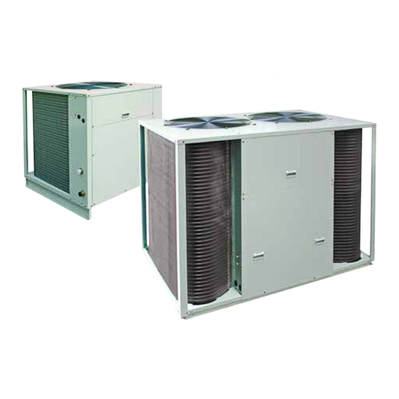
    GéNéRALITéS Les unités de condensation CDN 205 à 905 offrent 8 modèles pour des puissances frigorifiques de 19 à 83 kW permettant de répondre, dans cette gamme de puissance, aux applications de climatisation à caractère tertiaire ou industriel. De forme compacte, ces unités de condensation possèdent un très faible encombrement.
  • Page 23: Spécifications Techniques

    SPéCIFICATIONS TEChNIQUES MONO CIRCUIT Modèles 405M 18.6 27.8 35.1 Capacité frigorifique nominale (1) BTU/h 63466 94857 119766 puissance totale absorbée 6.49 12.4 en froid (1) Dimensions Unité Extérieure CDN Largeur 1003 1004 profondeur 1003 1004 Hauteur 1060 1094 1250 poids Diamètre raccordement (à...
  • Page 24: Bi Circuits

    BI CIRCUITS Modèles 44.4 55.6 69.1 Capacité frigorifique nominale (1) BTU/h 122837 151500 189715 235779 283208 puissance totale absorbée 16.1 22.9 27.5 en froid (1) Dimensions Unité Extérieure CDN Largeur 1708 1708 1708 2213 2213 profondeur 1123 1123 1123 1345 1345 Hauteur 1171...
  • Page 25: Schema Du Circuit Frigorifique

    SChEMA DU CIRCUIT FRIGORIFIQUE VOIR ANNEXE SPECTRES DE PUISSANCE ACOUSTIQUE NIVEAU DE PUISSANCE ACOUSTIQUE MONO CIRCUIT MODELES 405M dB(A) dB(A) dB(A) 61.1 64.5 68.0 68.3 71.6 73.0 Fréquence 69.9 76.1 76.4 1000 76.9 77.4 77.7 Octave 2000 72.6 75.5 74.7 4000 69.4 68.4...
  • Page 26: Guide De Sélection

    GUIDE DE SéLECTION pour les conditions différentes à celles indiquées dans les tableaux de performances, l’interpolation est autorisée; cependant, l’extrapolation est interdite. Température de l'air ambiant ≤ 25 (3) Modèles Temp Temp de d'évap rosé p frigo p Absorbée p frigo p Absorbée p frigo p Absorbée...
  • Page 27: Installation De L'unite

    INSTALLATION DE L’UNITE Dégagement minimum à prévoir pour accès à la maintenance. 800 mm Aire de service minimale (mm) MODELE 305 405M 405 IMPLANTATION Le groupe doit être installé sur une fondation horizontale stable, suffisamment robuste pour supporter son poids total en fonctionnement.
  • Page 28: Unité Exterieure À Un Niveau Superieur

    UNITé EXTERIEURE à UN NIVEAU SUPERIEUR 205 - 305 - 405 - 505 - 605 - 755 - 905 30m maxi placer un siphon sur la ligne Gaz tous les 5m. 25m maxi 405M 30m maxi 10m maxi UNITé EXTERIEURE à UN NIVEAU INFERIEUR Les lignes doivent avoir une pente mini de 1/250 vers l'unité...
  • Page 29: Schemas Electriques Types

    SChEMAS ELECTRIQUES TYPES VOIR ANNEXE N722 LEGENDE DES SChEMAS ELECTRIQUES SE :3214 CDN 205 / 305 3-phase 400/230 V+/-10% 50Hz SE :3492 CDN 405M 3-phase 400/230 V+/-10% 50Hz SE :3215 CDN 405 / 505 / 605 3-phase 400/230 V+/-10% 50Hz...
  • Page 30: Designation Des Reperes Des Schemas Electriques

    FO1/FO2 : sécurité du moteur MO1 / MO2 (réarmement automatique) Sp1/Sp2 : variateur électronique pressostatique TABLEAU 2 VALEUR Condensateur CDN 205/305 15 µF CDN 405/505/605 15 µF COMPOSANTS SPECIFIQUES POUR MOD.405M / 755 / 905 : ACS1/AS2 : convertisseur de fréquence triphasé...
  • Page 31: Plage Et Reglage Des Relais Thermiques Des Moteur Compresseurs, Calibre Des Contacteurs (Classe Ac3)

    PLAGE ET REGLAGE DES RELAIS ThERMIQUES DES MOTEUR COMPRESSEURS, CALIBRE DES CONTACTEURS (CLASSE AC3) MOMO CIRCUIT MODELE 405M Réglage relais thermique FT1/ FT2 plage 12 –18A 16 – 24A 12 –18A Réglage 20.7A F1 (gG) 1.6A 1.6A 1.6A F3 (gG) Contacteur AC3 BI CIRCUITS MODELE...
  • Page 32: Raccordement Electrique

    RACCORDEMENT ELECTRIQUE Ces machines sont équipées d’un interrupteur de proximité, faisant office de bornier d’alimentation générale. Possibilité de cadenasser l’interrupteur. Un disjoncteur ou un porte fusible (non fourni) doit être installé en amont de l’unité, conformément au schéma électrique; pour les calibres, se reporter aux spécifications électriques. Modéles Modéles 205 - 305 - 405M...
  • Page 33: Variateur De Fréquences

    VARIATEUR DE FRéQUENCES Cet équipement est installé sur les unités extérieures 405M, 755 et 905. ATTENTION VARIATEUR DE FRéQUENCES Réseaux en schéma IT (neutre isolé ou impédance) et réseaux à mise à la terre asymétrique : vous devez débrancher le filtre RFI interne en retirant la vis en EMC. ATTENTION! Si un variateur dont le filtre RFI n'est pas débranché...
  • Page 34: Maintenance

    MAINTENANCE INSTALLATION GéNéRALE Effectuer une inspection visuelle de l’ensemble de l’installation en service. Vérifier la propreté de l’installation en général et vérifier que les évacuations de condensats ne sont pas obstruées, particulièrement celle de la batterie d’évaporation, avant la saison d’été. Vérifier l’état du bac.
  • Page 35 INSTALLATION AND SELECTION MANUAL NOTICE D’INSTALLATION ET DE SELECTION INSTALLATION UND VORWÄhLER-hANDBUCh MANUALE DI SELEZIONE E DELL’INSTALLAZIONE MANUAL DE LA INSTALACIÓN Y DE LA SELECCIÓN...
  • Page 36 INhALT ALLGEMEINE EMPFEhLUNGEN .........................3 SICHERHEITSANWEISUNGEN ..............................3 WARNUNG ....................................3 ALLGEMEINES ............................4 KOMpRESSOR ..................................4 VERDAMpFER ................................... 4 LUFTGEKÜHLTE VERFLÜSSIGER ..............................4 VENTILATORAGGREGAT ................................4 SCHALTSCHRANK ..................................4 TEChNISChE DATEN ..........................5 EINFACHKREISLAUF .................................. 5 DOppELKREISLAUF ................................... 6 KÄLTETEChNISChE DATEN ........................6 EINFACHKREISLAUF ..................................
  • Page 37: Allgemeine Empfehlungen

    VOR JEDEM EINGRIFF IN DEN SChALTSChRÄNKEN UNBEDINGT NETZSTECKER ZIEhEN ALLGEMEINE EMPFEhLUNGEN Vor dem Installieren des Gerätes sind die folgenden Sicherheitsanweisungen aufmerksam durchzulesen. SIChERhEITSANWEISUNGEN Bei Eingriffen an Ihrem Gerät sind die geltenden Sicherheitsvorschriften zu befolgen. Installation, Gebrauch und Wartung müssen von qualifiziertem personal durchgeführt werden, das mit den Normen und örtlich geltenden Vorschriften gut vertraut ist und Erfahrung mit diesem Gerätetyp hat Zum Fördern des Gerätes müssen Systeme benutzt werden, die seinem Gewicht entsprechen.
  • Page 38: Allgemeines

    ALLGEMEINES Die Verflüssigereinheiten CDN 205 bis 905 stellen 8 Modelle für Kühlleistungen von 19 bis 83 kW bereit, mit denen in diesem Leistungsbereich die klimatechnischen Anwendungen auf dem industriellen Bereich oder dem Dienstleistungssektor gedeckt werden können. Der Raumbedarf dieser kompakten Verflüssigereinheiten ist sehr gering.
  • Page 39: Technische Daten

    TEChNISChE DATEN EINFAChKREISLAUF Modell 405M 18.6 27.8 35.1 Nennkühlleistung (1) BTU/h 63466 94857 119766 Gesamtleistungsaufnahme 6.49 12.4 im Kühlbetrieb (1) Maße Außeneinheit CDN Breite 1003 1004 Tiefe 1003 1004 Höhe 1060 1094 1250 Gewicht Verbindungsdurchmesser (hartzulöten) Saugleitung inch 1" 1/8" 1"...
  • Page 40: Doppelkreislauf

    DOPPELKREISLAUF Modell 44.4 55.6 69.1 Nennkühlleistung (1) BTU/h 122837 151500 189715 235779 283208 Gesamtleistungsaufnahme 16.1 22.9 27.5 im Kühlbetrieb (1) Maße Außeneinheit CDN Breite 1708 1708 1708 2213 2213 Tiefe 1123 1123 1123 1345 1345 Höhe 1171 1171 1304 1454 Gewicht Verbindungsdurchmesser (hartzulöten) Saugleitung...
  • Page 41 KÄLTEKREISLAUFDIAGRAMM SIEhE ANLAGE SChALLLEISTUNGSSPEKTREN SChALLLEISTUNGSPEGEL EINFAChKREISLAUF MODELL 405M dB(A) dB(A) dB(A) 61.1 64.5 68.0 68.3 71.6 73.0 Frequenz 69.9 76.1 76.4 1000 76.9 77.4 77.7 Oktave 2000 72.6 75.5 74.7 4000 69.4 68.4 74.1 Gesamt DOPPELKREISLAUF MODELL dB(A) dB(A) dB(A) dB(A) dB(A) 64.4...
  • Page 42: Auswahlanleitung

    AUSWAhLANLEITUNG Bei Bedingungen, die von den in den Leistungstabellen angegebenen Bedingungen abweichen, ist die Interpolation zulässig, die Extrapolation ist dagegen nicht gestattet. Umgebungslufttemperaturen Modell Temperatur Taupunkt- ≤ 25 (3) temperatur Kühlleistung Aufgenommene Kühlleistung Aufgenommene Kühlleistung Aufgenommene Kühlleistung Aufgenommene Kühlleistung Aufgenommene Verdampfer (kW) Leistung...
  • Page 43: Installation Der Einheit

    INSTALLATION DER EINhEIT Mindestens vorzusehender Freiraum für Wartungszwecke. 800 mm Minimale Betriebsfläche (mm) MODELL 305 405M 405 AUFSTELLUNGIMPLANTATION Das Aggregat muss auf einem tragfähigen, waagerechten Fundament installiert werden, das ausreichend solide ist, um das Gesamtbetriebsgewicht des Aggregates zu tragen. Zwischen dem Aggregat und der Tragestruktur muss ein Schwingungsisolator montiert werden –...
  • Page 44: Höher Liegende Ausseneinheit

    hÖhER LIEGENDE AUSSENEINhEIT 205 - 305 - 405 - 505 - 605 - 755 - 905 30m maxi 25m maxi Einen Siphon im Abstand von jeweils 5 mmdie Saugleitung installieren. 405M 30m maxi 10m maxi TIEFER LIEGENDE AUSSENEINhEIT D i e L e i t u n g e n m ü s s e n e i n Mindestgefälle von 1/250 in Richtung Außeneinheit haben.
  • Page 45: Stromlaufplan

    STROMLAUFPLAN SIEhE ANLAGE N722 ERLÄUTERUNG SE: 3214 CDN 205 / 305 3-phasen 400/230 V+/-10% 50Hz SE: 3492 CDN 405M 3-phasen 400/230 V+/-10% 50Hz SE: 3215 CDN 405 / 505 / 605 3-phasen 400/230 V+/-10% 50Hz SE: 3494 CDN 755 / 905 CONTROL...
  • Page 46: Bezeichnung Der Markierungen Der Stromlaufpläne

    : Kondensator Motor MO1 /MO2 (Siehe Tabelle 2) FO1/FO2 : Sicherheit von Motor MO1 / MO2 (selbsttätige Wiedereinschaltung) Sp1/Sp2 : druckgesteuertes elektronisches Regelgerät TABELLE 2 WERT Kondensator CDN 205/305 15 µF CDN 405/505/605 15 µF SPEZIFISChE BAUTEILE FüR MOD. 405M / 755 / 905: ACS1/AS2 : Drehstromfrequenzwandler...
  • Page 47: Bereich Und Regelung Der Überstromrelais Der Kompressormotoren, Dimensionierung Der Schütze (Klasse Ac3)

    BEREICh UND REGELUNG DER üBERSTROMRELAIS DER KOMPRESSORMOTOREN, DIMENSIONIERUNG DER SChüTZE (KLASSE AC3) EINFAChKREISLAUF MODELL 405M Regelung Überstromrelais FT1/ FT2 Bereich 12 –18A 16 – 24A 12 –18A Regelung 20.7A F1 (gG) 1.6A 1.6A 1.6A F3 (gG) Schütz AC3 DOPPELKREISLAUF MODELL Regelung Überstromrelais FT1/ FT2 Bereich...
  • Page 48: Elektrische Anschlüsse

    ELEKTRISChE ANSChLüSSE Diese Maschinen werden mit einem Näherungsschalter ausgestattet, der als Netzanschlussklemmleiste dient. Der Schalter kann mit einem Vorhängeschloss verschlossen werden. Ein Sicherungsautomat oder ein Sicherungshalter (nicht mitgeliefert) muss vor der Einheit entsprechend dem Stromlaufplan installiert werden; für die Dimensionierungen verweisen wir auf die elektrischen Daten. Modelle Modelle 205 - 305 - 405M...
  • Page 49: Frequenzwandler

    FREQUENZWANDLER Diese Ausstattung wird auf Außeneinheiten 405M, 755 und 905 installiert. WIChTIG FREQUENZWANDLER Bei einem IT- (erdfreien) und einem asymmetrisch geerdeten TN-System muss das interne EMV-Filter durch Entfernen der Schraube an EMC abgeschaltet werden. WARNUNG! Wird ein Frequenzumrichter, dessen EMV-Filter nicht abgeschaltet ist an ein IT-Netz [ein erdfreies oder hochohmig geerdetes (über 30 Ohm) Netz] angeschlossen, wird das Netz über die EMV-Filter-Kondensatoren des Frequenzumrichters mit dem Erdpotential verbunden.
  • Page 50: Wartung

    WARTUNG ALLGEMEINE ANLAGE Eine Sichtprüfung der gesamten Anlage in Betrieb vornehmen. Die Sauberkeit der Anlage im allgemeinen prüfen und kontrollieren, dass die Kondenswasserabflüsse nicht verstopft sind, besonders die der Verdampferbatterie vor der Sommersaison. Den Zustand der Kondensatwanne prüfen. Beschaffenheit und Spannung des (der) Riemen(s) der Einheiten Innere gegebenenfalls überprüfen. KÄLTEKREISLAUF Den Luftaustauscher mit einem speziellen produkt für Aluminium-Kupfer-Batterien reinigen und mit Wasser abspülen.
  • Page 51 INSTALLATION AND SELECTION MANUAL NOTICE D’INSTALLATION ET DE SELECTION INSTALLATION UND VORWÄHLER-HANDBUCH MANUALE DI SELEZIONE E DELL’INSTALLAZIONE MANUAL DE LA INSTALACIÓN Y DE LA SELECCIÓN...
  • Page 52 INDICE RACCOMANDAZIONI GENERALI ......................3 CONSIGLI DI SICUREZZA ................................. 3 AVVERTENZA ................................... 3 GENERALITA’ .............................4 COMpRESSORE ..................................4 EVApORATORE ..................................4 CONDENSATORI AD ARIA ................................ 4 GRUppO MOTO-VENTILATORE ..............................4 QUADRO ELETTRICO ................................4 SPECIFIChE TECNIChE ..........................5 CIRCUITO SINGOLO ................................5 CIRCUITO DOppIO ..................................
  • Page 53: Raccomandazioni Generali

    MESSA FUORI TENSIONE OBBLIGATORIA PRIMA DI OGNI INTERVENTO SULLE SCATOLE ELETTRIChE RACCOMANDAZIONI GENERALI Leggere attentamente le seguenti avvertenze di sicurezza prima di installare l’apparecchio. CONSIGLI DI SICUREZZA Quando intervenite sul vostro materiale, seguite le regole di sicurezza in vigore. L’installazione, l’utilizzo e la manutenzione devono essere eseguiti da personale qualificato che conosca bene la legislazione e la regolamentazioni locali e avente una certa esperienza per quanto riguarda questo tipo di attrezzature.
  • Page 54: Generalita

    GENERALITA’ Le unità di condensazione CDN 205 - 905 offrono 8 modelli con potenze refrigeranti comprese tra 19 e 83 kW che permettono di rispondere, in questa gamma di potenza, alle applicazioni di climatizzazione terziaria o industriale. Di forma compatta, queste unità di condensazione hanno un ingombro molto ridotto.
  • Page 55: Specifiche Tecniche

    SPECIFIChE TECNIChE CIRCUITO SINGOLO Modelli 405M 18.6 27.8 35.1 Capacité frigorifique nominale (1) BTU/h 63466 94857 119766 potenza totale assorbita 6.49 12.4 durante il raffreddamento (1) Dimensioni Unità Esterna CDN Larghezza 1003 1004 profondità 1003 1004 Altezza 1060 1094 1250 peso Diametro collegamento (a brasare) inch...
  • Page 56: Circuito Doppio

    CIRCUITO DOPPIO Modelli 44.4 55.6 69.1 Capacité frigorifique nominale (1) BTU/h 122837 151500 189715 235779 283208 potenza totale assorbita 16.1 22.9 27.5 durante il raffreddamento (1) Dimensioni Unità Esterna CDN Larghezza 1708 1708 1708 2213 2213 profondità 1123 1123 1123 1345 1345 Altezza...
  • Page 57: Schema Del Circuito Refrigerante

    SChEMA DEL CIRCUITO REFRIGERANTE VEDERE ALLEGATO SPETTRI DI POTENZA ACUSTICA LIVELLO DI POTENZA ACUSTICA CIRCUITO SINGOLO MODELLI 405M dB(A) dB(A) dB(A) 61.1 64.5 68.0 68.3 71.6 73.0 69.9 76.1 76.4 Frequenza in Ottave 1000 76.9 77.4 77.7 2000 72.6 75.5 74.7 4000 69.4...
  • Page 58: Guida Di Selezione

    GUIDA DI SELEZIONE per condizioni diverse da quelle indicate nelle tabelle di prestazioni, l’interpolazione è autorizzata. Temperatura dell’aria ambiente Modelli Temp. Temp. ≤ 25 (3) evaporatore brina p frigorifera p Assorbita p frigorifera p Assorbita p frigorifera p Assorbita p frigorifera p Assorbita p frigorifera p Assorbita...
  • Page 59: Nstallazione Dell'unita

    NSTALLAZIONE DELL’UNITA’ prevedere un disimpegno minimo per accesso alla manutenzione. 800 mm Area di servizio minima (mm) MODELLI 305 405M 405 UBICAZIONE Il gruppo deve essere installato su fondamenta orizzontali stabili, sufficientemente solide per poter supportare il suo peso totale durante il funzionamento. Si dovrà montare un isolatore di vibrazioni – per esempio supporti ammortizzatori in gomma –...
  • Page 60: Unità Estera Ad Un Livello Superiore

    UNITà ESTERA AD UN LIVELLO SUPERIORE 205 - 305 - 405 - 505 - 605 - 755 - 905 30m maxi 25m maxi Montare un sifone sulla linea Gas ogni 5 405M 30m maxi 10m maxi UNITà ESTERA AD UN LIVELLO INFERIORE Le linee devono avere una pendenza di almeno 1/250 verso l’unità...
  • Page 61: Schema Eletrico

    SChEMA ELETRICO VEDERE ALLEGATO N722 DIDASCALIA DEGLI SChEMI ELETTRICI SE :3214 CDN 205 / 305 Trifase 400/230 V+/-10% 50Hz SE :3492 CDN 405M Trifase 400/230 V+/-10% 50Hz SE :3215 CDN 405 / 505 / 605 Trifase 400/230 V+/-10% 50Hz SE :3494...
  • Page 62: Designazione Delle Posizioni Degli Schemi Elettrici

    FO1/FO2 : sicurezza del motore MO1 / MO2 (riarmo automatico) Sp1/Sp2 : variatore elettronico pressostatico TABELLA 2 VALORE Condensatore CDN 205/305 15 µF CDN 405/505/605 15 µF COMPONENTI SPECIFICI PER MOD. 405M / 755 / 905 ACS1/AS2 : convertitore di frequenza trifase...
  • Page 63: Intervallo E Regolazione Dei Rele' Termici Dei Motori Compressori, Calibro Dei Contatori (Classe Ac3)

    INTERVALLO E REGOLAZIONE DEI RELE’ TERMICI DEI MOTORI COMPRESSORI, CALIBRO DEI CONTATORI (CLASSE AC3) CIRCUITO SINGOLO MODELLO 405M Regolazione relé termico FT1/ FT2 Intervallo 12 –18A 16 – 24A 12 –18A Regolazione 20.7A F1 (gG) 1.6A 1.6A 1.6A F3 (gG) Contatore AC3 CIRCUITO DOPPIO MODELLO...
  • Page 64: Collegamento Elettrico

    COLLEGAMENTO ELETTRICO Queste macchine sono equipaggiate con un interruttore di prossimità, che funge da morsettiera di alimentazione generale. Possibilità di chiudere con un lucchetto l’interruttore. Un interruttore o un porta fusibile (non fornito) deve essere installato a monte dell’unità, in conformità con lo schema elettrico;...
  • Page 65: Variatore Di Frequenze

    VARIATORE DI FREQUENZE Quest’attrezzatura è installata su unità esterne 405M, 755 e 905. ATTENZIONE VARIATORE DI FREQUENZE Nei sistemi IT (senza messa a terra) e nei sistemi TN con una fase a terra, scollegare il filtro EMC interno rimuovendo la vite in corrispondenza di EMC. AVVERTENZA! Se si installa un convertitore con filtro EMC non scollegato su un sistema IT [un sistema di alimentazione privo di messa a terra o un sistema con messa a terra ad alta resistenza (superiore a 30 ohm)], il sistema sarà...
  • Page 66: Manutenzione

    MANUTENZIONE INSTALLAZIONE GENERALE Eseguire un’ispezione generale dell’insieme dell’installazione in funzione. Verificare che l’installazione, in generale, sia pulita e verificare che gli scarichi delle condense non siano otturati, in particolare quello della batteria di evaporazione, prima della stagione estiva. Verificare lo stato del serbatoio. Verificare all'occorrenza lo stato e la tensione della(e) cinghia(e) degli unità...
  • Page 67 INSTALLATION AND SELECTION MANUAL NOTICE D’INSTALLATION ET DE SELECTION INSTALLATION UND VORWÄHLER-HANDBUCH MANUALE DI SELEZIONE E DELL’INSTALLAZIONE MANUAL DE LA INSTALACIóN Y DE LA SELECCIóN...
  • Page 68 SUMARIO RECOMENDACIONES GENERALES ......................3 CONSEJOS DE SEGURIDAD ..............................3 ADVERTENCIA ..................................3 GENERALIDADES ............................4 COMpRESOR ................................... 4 EVApORADOR ..................................4 CONDENSADORES DE AIRE ..............................4 GRUpO MOTOVENTILADOR ..............................4 ARMARIO ELéCTRICO ................................4 ESPECIFICACIONES TéCNICAS........................5 MONOCIRCUITO ..................................5 BICIRCUITO ..................................... 6 ESPECIFICACIONES FRIGORÍFICAS ......................6 MONOCIRCUITO ..................................
  • Page 69: Recomendaciones Generales

    ANTES DE CUALQUIER INTERVENCIóN EN LAS CAJAS ELéCTRICAS, ES OBLIGATORIO PONER EL EQUIPO FUERA DE TENSIóN RECOMENDACIONES GENERALES Antes de instalar el aparato, leer atentamente las siguientes consignas de seguridad. CONSEJOS DE SEGURIDAD Cuando intervenga en su equipo, respete las reglas de seguridad en vigor. La instalación, utilización y mantenimiento deben ser realizados por personal cualificado, que conozca perfectamente la legislación y la normativa locales y que tenga experiencia en este tipo de equipos.
  • Page 70: Generalidades

    GENERALIDADES Las unidades de condensación CDN 205 a 905 ofrecen 8 modelos para potencias frigoríficas de 19 a 83 kW, que permiten responder, en la gama de esta potencia, a las aplicaciones de climatización de carácter terciario o industrial. Estas unidades de condensación, de forma compacta, ocupan un volumen muy reducido.
  • Page 71: Especificaciones Técnicas

    ESPECIFICACIONES TéCNICAS MONOCIRCUITO Modelos 405M 18.6 27.8 35.1 Capacidad frigorífica BTU/h 63466 94857 119766 nominal (1) potencia total absorbida 6.49 12.4 en frío (1) Dimensiones Unidad Exterior CDN 1003 1004 Anchura profundidad 1003 1004 Altura 1060 1094 1250 peso Diámetro conexión (a soldar) inch 1"...
  • Page 72: Bicircuito

    BICIRCUITO Modelos 44.4 55.6 69.1 Capacidad frigorífica BTU/h 122837 151500 189715 235779 283208 nominal (1) potencia total absorbida en 16.1 22.9 27.5 frío (1) Dimensiones Unidad Exterior CDN 1708 1708 1708 2213 2213 Anchura 1123 1123 1123 1345 1345 profundidad 1171 1171 1304...
  • Page 73: Esquema Del Circuito Frigorífico

    ESQUEMA DEL CIRCUITO FRIGORÍFICO VER ANEXO ESPECTROS DE POTENCIA ACÚSTICA NIVEL DE POTENCIA ACÚSTICA MONOCIRCUITO MODELOS 405M dB(A) dB(A) dB(A) 61.1 64.5 68.0 68.3 71.6 73.0 69.9 76.1 76.4 Frecuencia en Octava 1000 76.9 77.4 77.7 2000 72.6 75.5 74.7 4000 69.4 68.4...
  • Page 74: Guía De Selección

    GUÍA DE SELECCIóN para unas condiciones diferentes a las indicadas en los cuadros de prestaciones, se permite la interpolación; sin embargo, está prohibida la extrapolación. Temperatura del aire ambiente ≤ 25 (3) Modelos Temp. Temp. de evaporador rocío(2) p frigo p absorbida p frigo p absorbida...
  • Page 75: Instalación De La Unidad

    INSTALACIóN DE LA UNIDAD Espacio mínimo que hay que prever para acceder al mantenimiento. 800 mm Área de servicio mínima (mm TIpOS 305 405M 405 IMPLANTACIóN El grupo debe instalarse sobre una cimentación horizontal estable, lo bastante sólida para soportar su peso total en funcionamiento.
  • Page 76: Unitad Exterior En Un Nivel Superior

    UNITAD EXTERIOR EN UN NIVEL SUPERIOR 205 - 305 - 405 - 505 - 605 - 755 - 905 30m maxi 25m maxi Instalar un sifón en la línea Gas cada 5 m. 405M 30m maxi 10m maxi UNITAD EXTERIOR EN UN NIVEL INFERIOR Las líneas deben tener una pendiente mínima de 1/250 hacia la unidad exterior.
  • Page 77: Esquemas Eléctricos Tipo

    ESQUEMAS ELéCTRICOS TIPO VER ANEXO N722 LEYENDA DE LOS ESQUEMAS ELéCTRICOS SE: 3214 CDN 205 / 305 3-Fase 400/230 V ± 10% 50 Hz SE: 3492 CDN 405M 3-Fase 400/230 V ± 10% 50 Hz SE: 3215 CDN 405 / 505 / 605 3-Fase 400/230 V ±...
  • Page 78: Designación De Las Indicaciones De Los Esquemas Eléctricos

    FO1/FO2 : seguridad del motor MO1 / MO2 (rearme automático). Sp1/Sp2 : variador electrónico presostático. CUADRO 2 VALOR Condensador CDN 205/305 15 µF CDN 405/505/605 15 µF COMPONENTES ESPECÍFICOS PARA EL MOD.405M / 755 / 905 ACS1/AS2 : convertidor de frecuencia trifásico.
  • Page 79: Gama Y Ajuste De Los Relés Térmicos De Los Motores Compresores, Calibre De Los Contactores (Clase Ac3)

    GAMA Y AJUSTE DE LOS RELéS TéRMICOS DE LOS MOTORES COMPRESORES, CALIBRE DE LOS CONTACTORES (CLASE AC3) MONOCIRCUITO MODELO 405M Ajuste relé térmico FT1/ FT2 Gama 12 –18A 16 – 24A 12 –18A Ajuste 20.7A F1 (gG) 1.6A 1.6A 1.6A F3 (gG) Contactor AC3 BICIRCUITO...
  • Page 80: Conexión Eléctrica

    CONEXIóN ELéCTRICA Estas máquinas van equipadas con un interruptor de proximidad que hace las veces de placa de bornes de alimentación general. Es posible bloquear el interruptor. Antes de la unidad, hay que instalar un disyuntor o un portafusibles (no incluidos), de conformidad con el esquema eléctrico.
  • Page 81: Variador De Frecuencias

    VARIADOR DE FRECUENCIAS Este equipamiento se instala sobre unidades exteriores 405M, 755 y 905. ATENCIóN VARIADOR DE FRECUENCIAS En sistemas IT (sin conexión de neutro a tierra) y sistemas TN con conexión a tierra en un vértice, desconecte el filtro EMC interno retirando el tornillo de EMC. ADVERTENCIA Si se instala un convertidor de frecuencia cuyo filtro EMC no está...
  • Page 82: Mantenimiento

    MANTENIMIENTO INSTALACIóN GENERAL Realizar una inspección visual del conjunto de la instalación en servicio. Comprobar la limpieza de la instalación en general y verificar que las evacuaciones de condensados no están obstruidas, especialmente la de la batería de evaporación, antes de la temporada de verano. Comprobar el estado de la bandeja.
  • Page 83 APPENDIX ANNEXE ANLAGE ALLEGATO ANEXO...
  • Page 84: Annexe

    ANNEXE / ANNEXE / ANLAGE / ALLEGATO / ANEXO APPENDIX DIMENSIONS ................................III 205 ..................................................III 305 ..................................................IV 405M ..................................................V 405 - 505 - 605 ............................................... VI 755 - 905 ................................................VII REFRIGERANT CIRCUIT DIAGRAM ..........................VIII VERSION BAL ................................................IX VERSION BAZ ................................................IX VERSION BAC ................................................IX WIRING DIAGRAM .................................
  • Page 85 ANNEXE / ANNEXE / ANLAGE / ALLEGATO / ANEXO DIMENSIONS DIMENSIONS ABMESSUNGEN DIMENSIONI DIMENSIONES...
  • Page 86 ANNEXE / ANNEXE / ANLAGE / ALLEGATO / ANEXO 1003...
  • Page 87 ANNEXE / ANNEXE / ANLAGE / ALLEGATO / ANEXO 405M 4Ø10 1004...
  • Page 88 ANNEXE / ANNEXE / ANLAGE / ALLEGATO / ANEXO 405 - 505 - 605 1708 1650 1171 1171 505 - 605...
  • Page 89 ANNEXE / ANNEXE / ANLAGE / ALLEGATO / ANEXO 755 - 905 2175 1048 1070 1309 1459 2213...
  • Page 90 ANNEXE / ANNEXE / ANLAGE / ALLEGATO / ANEXO REFRIGERANT CIRCUIT DIAGRAM SChEMA DU CIRCUIT FRIGORIFIQUE KÄLTEKREISLAUFDIAGRAMM SChEMA DEL CIRCUITO REFRIGERANTE ESQUEMA DEL CIRCUITO FRIGORÍFICO 1 COMpRESSOR 1 COMpRESSEUR 2 CONDENSER COIL 2 CONDENSEUR 3 FILTER-DRIER 3 FILTRE DESHYDRATEUR 4 LIQUID LINE RESERVE 4 BOUTEILLE RESERVOIR LIQUIDE 5 SUCTION ACCUMULATOR 5 BOUTEILLE ANTI-COUp LIQUIDE...
  • Page 91 ANNEXE / ANNEXE / ANLAGE / ALLEGATO / ANEXO VERSION BAZ VERSION BAC VERSION BAL The pressure takeoffs are directed outdoors Les prises de pressions sont ramenées à l’extérieure. Die Druckanschlussstellen sind nach außen verlegt. Le prese di pressione sono riportati all’esterno. Las tomas de presión se ponen en el exterior.
  • Page 92 ANNEXE / ANNEXE / ANLAGE / ALLEGATO / ANEXO WIRING DIAGRAM SChEMAS ELECTRIQUES STROMLAUFPLANS SChEMA ELETRICO ESQUEMA ELECTRICO TAKE CARE! These wiring diagrams are correct at the time of publication. Manufacturing changes can lead to modifications. Always refer to the diagram supplied with the product. ATTENTION Ces schémas sont corrects au moment de la publication.
  • Page 93 ANNEXE / ANNEXE / ANLAGE / ALLEGATO / ANEXO 205 305...
  • Page 94 ANNEXE / ANNEXE / ANLAGE / ALLEGATO / ANEXO 405M...
  • Page 95 ANNEXE / ANNEXE / ANLAGE / ALLEGATO / ANEXO 405 - 505 - 605 XIII...
  • Page 96 ANNEXE / ANNEXE / ANLAGE / ALLEGATO / ANEXO 755 - 905 CONTROL...
  • Page 97 ANNEXE / ANNEXE / ANLAGE / ALLEGATO / ANEXO 755 - 905 POWER...
  • Page 98 ANNEXE / ANNEXE / ANLAGE / ALLEGATO / ANEXO...
  • Page 99: Ec Compliance Declaration

    CDN 205 - CDN 305 - CDN 405M - CDN 405 - CDN 405 - CDN 505 - CDN 605 - CDN 755 - CDN 905 CWDN 205 - CWDN 305 - CWDN 405M - CWDN 405 - CWDN 405 - CWDN 505 - CWDN 605 - CWDN 755 - CWDN 905...
  • Page 100 AIRWELL I ndustrIe rance Route de Verneuil 27570 Tillières-sur-Avre FRANCE : +33 (0)2 32 60 61 00 & : +33 (0)2 32 32 55 13 As part of our ongoing product improvement programme, our products are subject to change without prior notice. Non contractual photos.

Ce manuel est également adapté pour:

Cdn 305Cdn 405mCdn 405Cdn 505Cdn 605Cdn 755 ... Afficher tout

Table des Matières