Table des Matières
Publicité
Les langues disponibles
Les langues disponibles
Liens rapides
In USA - BEST Hartford, Wisconsin
In CANADA - BEST Drummondville, QC, Canada
REGISTER YOUR PRODUCT ONLINE AT : www.BestRangeHoods.com/register
For additional Information visit www.BestRangeHoods.com
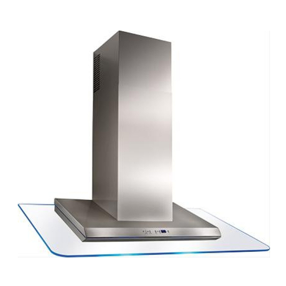
Model WC26I
ENGLISH.....................................2
FRANÇAIS................................15
ESPAÑOL..................................28
Publicité
Table des Matières

Manuels Connexes pour Best WC26I


Sommaire des Matières pour Best WC26I
- Page 1 Model WC26I ENGLISH........2 FRANÇAIS........15 ESPAÑOL........28 In USA - BEST Hartford, Wisconsin In CANADA - BEST Drummondville, QC, Canada REGISTER YOUR PRODUCT ONLINE AT : www.BestRangeHoods.com/register For additional Information visit www.BestRangeHoods.com...
- Page 2 READ AND SAVE THESE INSTRUCTIONS INTENDED FOR DOMESTIC COOKING ONLY WARNING TO REDUCE THE RISK OF FIRE, ELECTRIC SHOCK, OR INJURY TO PERSONS, OBSERVE THE FOLLOWING: 1. Use this unit only in the manner intended by the manufacturer. If you have questions, contact the manufacturer at the address or telephone number listed in the warranty.
- Page 3 8. For best capture of cooking impurities, the bottom of the hood should be a minimum of 22" and a maximum of 28" above the cooking surface. See “Install Mounting Bracket”...
-
Page 4: The Led Display
OPERATION Controls The hood is operated using the (5) push buttons located on the front edge of the hood. The Light switch turns the halogen lights on and off. Push the light switch once to turn the lights ON - push a second time to turn the lights ON to a brighter level - push a third time to turn the lights OFF. -
Page 5: Fuse Replacement
HALOGEN BULBS This range hood requires two halogen bulbs (Type T3, 12Volt, 20Watt Max, G-4 Base). WARNING: Always switch off the elec- trical supply before carrying out any op- eration on the appliance. To change bulbs: 1. Open the cover by prying from the proper slots. - Page 6 MAINTENANCE Proper maintenance of the Range Hood will assure proper performance of the unit. Grease Filter The grease filter should be cleaned frequently. Use a warm detergent solution. Grease filter is dishwasher safe. See “INSTALL FILTERS” section for removal and installation instructions. Non-ducted Recirculation Filter The non-ducted recirculation filter should be changed every 6 months.
-
Page 7: Prepare The Hood
PREPARE THE HOOD Unpack hood and check contents. You should receive: 1 - Hood 1 - Decorative Flue Assembly 1 - Parts Bag (B080810707) containing: 1 - Mounting Bracket 1 - Discharge Collar 1 - Flue Mounting Bracket 8 - Mounting Screws (4.8 x 38mm Pan Head) 7 - Mounting Screws (3.9 x 9.5mm Pan Head) 2 - Mounting Screws (3.9 x 6mm Flat Head) 8 - Drywall Anchors... - Page 8 3. Long duct runs, elbows, and transitions will reduce the performance of the hood. Use as few of them as possible. Larger ROUND HOOD ducting may be required for best ELBOW performance with longer duct runs. 6” 4. Install a roof or wall cap. Connect round...
- Page 9 Notes: a. Minimum hood distance above cook top must not be less than 22”. A maximun of 28” above cook top is highly recommended for best capture of cooking impurities. Distances over 28” are at the installer and user’s discretion; and if ceiling height and flue length permits.
- Page 10 INSTALL FLUE MOUNTING FLUE MOUNTING BRACKET BRACKET 3.9 x 6 mm FLAT HEAD BRACKET SCREWS DUCTED AND NON-DUCTED HOODS 1. Assemble the flue mounting bracket, adjusting outside width as shown. Fig.8 2. Carefully center the mounting bracket directly over the range hood location. 9-13/16”...
- Page 11 PREPARE THE HOOD NON - DUCTED HOODS ONLY Note: The following materials must be purchased separately for non-ducted recirculation installations. • Non - Ducted Recirculation Kit, Model ANKWC26. 1. Remove the tape on the electrical system plate; place the electrical system plate on the hood (use a protection).
- Page 12 INSTALL THE WALL FRAMING MOUNTING SCREWS HOOD (3.9x9.5mm) DUCTED NON- RECTANGULAR DUCTED HOODS CUTOUT Note: at least two people will be required to mount the hood. MOUNTING 1. Raise the hood into its SCREWS (4.8x38mm) mounting position. MOUNTING BRACKET 2. Align the rectangular opening on the back of the hood with the wall- mounting bracket.
- Page 13 INSTALL THE HOOD, cont’d 9. Carefully place the decorative flue on the hood. Fig. 16. - On ducted installation in rooms with 8-foot ceilings, the air vents are concealed. Install the flue with the air vents down. - On non-ducted installations in rooms with 8-foot ceilings, the air vents are exposed.
-
Page 14: Install Filters
ONE YEAR LIMITED WARRANTY FOR BEST PRODUCTS Broan-NuTone LLC (Broan-NuTone) warrants to the original consumer purchaser of Best products that such products will be free from defects in materials or workmanship for a period of one year from the date of original purchase. THERE ARE NO OTHER WARRANTIES, EXPRESS OR IMPLIED, INCLUDING, BUT NOT LIMITED TO, IMPLIED WARRANTIES OR MERCHANT ABILITY OR FITNESS FOR A PARTICULAR PURPOSE. -
Page 15: Avertissements
LISEZ ET CONSERVEZ CES INSTRUCTIONS SEULEMENT POUR UTILISATION DOMESTIQUE AVERTISSEMENTS POUR REDUIRE LES RISQUES D’INCENDIE, DE DECHARGES ELECTRIQUES OU DE DOMMAGES AUX PERSONNES, OBSERVEZ LES INSTRUCTIONS SUIVANTES: 1. N’utilisez cet appareil que comme cela est indiqué par le constructeur. Si vous avez des problèmes, contactez le fabriquant à... - Page 16 4. Utilisez un extincteur SEULEMENT si: A. Vous savez que vous avez un extincteur Classe ABC, et vous en connaissez déjà le mode d’emploi. B. Ce n’est pas un très gros incendie et qu’il se limite à l’endroi où il a explosé. C.
-
Page 17: Fonctionnement
FONCTIONNEMENT Commandes La hotte fonctionne à l’aide de cinq (5) boutons-poussoirs situés sur le bord antérieur de votre hotte. Le Bouton de la lumière allume et éteint les lampes halogènes. En pressant 1 fois la touche, la lumière s’allume au 1 niveau;... -
Page 18: Remplacement Fusible
AMPOULES HALOGENES Ce modèle de hotte veut deux (2) ampoules halogènes (Type T3, 12Volt, 20 Watt Max, G- 4 Base). ATTENTION: avant de procéder à quelconque opération, débranchez l’appareil. Pour changer les ampoules: 1. Ouvrez le couvercle en faisant levier grâce aux fissures prévues à... -
Page 19: Entretien
ENTRETIEN Un bon entretien de votre hotte garantira une excellente performance. Filtre anti-graisse Le filtre anti-graisse doit être nettoyé fréquemment. Utilisez une solution contenant un détergent tiède. Le filtre anti-graisse peut être lavé au lave-vaisselle. Voir la section “INSTALLER LES FILTRES” pour les instructions relatives au démontage et à... - Page 20 PREPAREZ LA HOTTE Enlever la hotte dans l’emballage et controller le contenu. Vous devez recevoir : 1 - Hotte 1 - Conduit décoratif 1 - Sachet (B080810707) avec: 1 - Étrier d’assemblage 1 - Collier d’évacuation 1 - Étrier de support 8 - Vis d’assemblage (4.8 x 38mm Tête ronde) 7 - Vis d’assemblage (3.9 x 9.5mm Tête ronde) 2 - Vis d’assemblage (3.9 x 6 mm Tête plate)
-
Page 21: Installation Du Systeme D'evacuation
INSTALLATION DU COUVERCLE DU TOIT SYSTEME D’EVACUATION TUYAU ROND DE 6” UNIQUEMENT POUR LES HOTTES AVEC TUYAU D’EVACUATION ATTENTION: Pour réduire les risques d’incendie, n’utilisez que des tuyaux en métal. CONDUIT DÉCORATIF 1. Décidez où le tuyau rond doit être installé, COU- VERCLE entre votre hotte et l’extérieur. -
Page 22: Installation Etrier D'assemblage
INSTALLATION ETRIER CADRE DERRIÈRE D’ASSEMBLAGE L’APPUI TRANSVERSAL EN BOIS MODELE AVEC TUYAU D’EVACUATION ET MODELE RECYCLANT L’AIR. 1. Construisez un cadre en bois pour le mur dont les vis-pivot ne dépassent pas. Fig. 7. Assurez-vous: a) que le cadre est centré au-dessus de l’emplacement de l’installation. - Page 23 INSTALLATION ETRIER DE ETRIER DE 3.9 x 6 mm VIS SUPPORT DU CONDUIT SUPPORT DU D’ASSEMBLAGE À CONDUIT TÊTE PLATE DECORATIF DECORATIF MODELE AVEC TUYAU D’EVACUATION ET MODELE RECYCLANT L’AIR. Assemblez l’étrier de support du conduit décoratif en réglant la largeur extérieure comme indiqué.
- Page 24 PRÉPARATION DE LA HOTTE CONFIGURATION RECYCLANT L’AIR Remarque: Le matériel suivante doit être acheté séparément pour les configurations recyclant l’air. • version recyclant l’air, modèle ANKWC26. 1. Retirer le ruban adhésif sur la plaque de l’installation électrique; placer la plaque sur la hotte (utiliser une protection). N’utilisez pas le collier d’évacuation/ clapet fournis avec la hotte.
-
Page 25: Installation De La Hotte
INSTALLATION PLANCHE DE BOIS VIS D’ASSEMBLAGE POUR L'ADAPTATION (3.9x9.5mm) DE LA HOTTE MODELE AVEC TUYAU D’EVACUATION ET MODELE RECYCLANT D’ASSEMBLAGE L’AIR. (4.8x38mm) Remarque : la hotte doit ETRIER être installée par au moins D’ASSEMBLAGE deux personnes. Soulevez la hotte et placez-la à... - Page 26 INSTALLATION DE LA HOTTE, suite 9. Placez précautionneusement le conduit décoratif sur la hotte (Fig. 16). - Pour les hottes avec tuyau d’évacuation, lorsque le plafond est de 8’, les prises d’air du conduit supérieur sont dissimulées. Installez le conduit avec les prises d’air vers le bas.
-
Page 27: Installer Les Filtres
GARANTIE LIMITÉE DE UN AN DE BEST Broan-NuTone LLC (Broan-NuTone) garantit à l'acheteur original que les produits BEST vendus en vertu de la présente sont libres de tout vice de matériau ou de fabrication pour une période de un an à compter de la date d'achat originale. CETTE GARANTIE NE COMPORTE AUCUNE AUTRE GARANTIE, EXPRESSE OU TACITE, Y COMPRIS, MAIS SANS S'Y LIMITER, LES GARANTIES TACITES DE VALEUR MARCHANDE OU D'ADAPTATION À... - Page 28 LEA Y CONSERVE ESTAS INSTRUCCIONES INDICADO PARA EL USO EN COCINAS DOMESTICAS ADVERTENCIA PARA EVITAR EL RIESGO DE INCENDIO, CORTOCIRCUITO O DAÑO PARA LAS PERSONAS, OBSERVE ATENTAMENTE LAS SIGUIENTES NORMAS: 1. Use esta unidad solamente de la manera indicada por el fabricante; si tiene dudas, póngase en contacto con éste a la dirección o teléfono indicados en la garantía.
- Page 29 ADVERTENCIA 1. Para uso en interiores. 2. Para reducir el riesgo de incendios y para evacuar correctamente los humos, asegurarse de haber realizado una conducción del aire hasta el exterior. No expulsar los humos en espacios cerrados por paredes o techos, áticos, espacios angostos o garajes. 3.
- Page 30 FUNCIONAMIENTO Mandos La campana se opera mediante los 5 botones pulsadores que se encuentran el frontal de la campana. El interruptor luz enciende y apaga las lámparas halógenas. Pulsando el botón una vez, la luz se enciende a intensidad 1, pulsándolo una segunda vez, la luz se enciende a intensidad 2 (luz más intensa) y, pulsándolo otra vez más, la luz se apaga completamente.
- Page 31 LAMPARAS HALOGENAS Este tipo de campana necesita dos (2) lámparas halógenas (Tipo T3, 12Volt, 20 Watt Max, G-4 Base). ATENCIÓN: antes de proceder a cualquier operación, es necesario desco- nectar el aparato. Para cambiar las lámparas: 1. Abra la tapa haciendo palanca sobre las hendiduras apropiadas.
- Page 32 MANTENIMIENTO Un mantenimiento adecuado de la campana asegura el funcionamiento correcto del aparato. Filtro antigrasa El filtro antigrasa debe limpiarse con frecuencia. Use un detergente que no sea fuerte.Use un detergente que no sea fuerte. El filtro antigrasa se puede meter en el lavavajillas.
-
Page 33: Prepare La Campana
PREPARE LA CAMPANA Sacar la campana de l’embalaje y controlar el contenido. Recivireis: 1 - Campana 1 - Tubo decorativo 1 - Bolsita (B080810707) con: 1 - Soporte de montaje 1 - Casquillo 1 - Soporte para el montaje del tubo 8 - Tornillos de montaje (4.8x38mm cabeza redonda) 7 - Tornillos de montaje (3.9x9.5mm cabeza redonda) 2 - Tornillos de montaje (3.9x6 mm cabeza plano) -
Page 34: Instalacion Electrica
INSTALACION DEL TUBO DE UBIERTA DEL TEJADO EXTRACCION TUBO 6” SÓLO CAMPANAS CON CONDUCTO ATENCIÓN: para evitar el riesgo de incendio, use solamente material de metal. 1. Decida donde va a colocar el tubo de T U B O extracción entre la campana y la parte exterior. DECORATIVO TAPA 2. - Page 35 INSTALACION SOPORTE DE MARCO POSTERIOR DEL MONTAJE APOYO TRANVERSAL DE MADERA CON CONDUCTO Y SIN CONDUCTO 1. Construya una estructura de madera en la pared que quedará nivelada con la parte interior de los tacos en la pared. Fig.7. Asegúrese de que: a) La estructura se encuentra centrada por encima de la instalación del tubo.
- Page 36 INSTALACIÓN DEL SOPORTE PARA TORNILLOS DE SOPORTE PARA MONTAJE DE EL MONTAJE DEL TUBO EL MONTAJE CABEZA PLANA DEL TUBO DE 3.9 x 6 mm CON CONDUCTO Y SIN CONDUCTO 1. Ensamble el soporte para el montaje del tubo, ajustando el ancho exterior tal como se muestra.
-
Page 37: Preparación De La Campana
PREPARACIÓN DE LA CAMPANA CONFIGURACIÓN SIN CONDUCTO Nota: Los siguientes materiales deben comprarse por separado para instalaciones de recirculación sin conducto. • Equipo de recirculación sin conducto, modelo ANKWC26. 1. Retire la cinta de la placa del sistema eléctrico y coloque la placa en la campana (use una protección). -
Page 38: Instalación De La Campana
INSTALACIÓN DE ESTRUCTURA DE TORNILLOS DE MONTAJE MADERA EN LA PARED (3.9x9.5mm) LA CAMPANA CON CONDUCTO Y SIN CONDUCTO TORNILLOS DE MONTAJE Nota: se necesitan al (4.8x38mm) menos dos personas para montar la campana. SOPORTE DE MONTAJE 1. Levante la campana en su posición de montaje. - Page 39 INSTALACIÓN DE LA CAMPANA, (cont) 9. Coloque con cuidado la chimenea decorativa sobre la campana. Fig. 16. - En instalaciones con conducto en salas con techos de 8 pies, los respiraderos están ocultos. Monte el tubo con los respiraderos hacia abajo. - En instalaciones sin conducto en salas con techos de 8 pies, los respiraderos están expuestos.
- Page 40 GARANTIA BEST POR UN AÑO Broan-NuTone LLC (Broan-NuTone) garantiza al consumidor-comprador de sus productos BEST que dichos productos no tendrán defectos en los materiales o fabricación, durante un periodo de un año a partir de la fecha de la compra.NO HAY OTRO TIPO DE GARANTIAS QUE INCLUYAN O SE LIMITEN EXCLUSIVAMENTE A GARANTIAS IMPLICITAS O DE CAPACIDAD COMERCIAL O CONVENIENCIA PARA UN PROPOSITO ESPECIFICO.
-
Page 41: Service Parts
SERVICE PARTS MODEL WC26I KEY NO. PART NO. DESCRIPTION BE3348101 Filter Support B08087169 Grease Filter B02300233 Motor Capacitor BE3348100 Electrical Box Support B03295005 Transformer Protection B02300891 Halogen Lamp Bulb B02300804 Heat Sentry B03292357 Electrical Box B03294033 Electrical Box Cover BW0000019... -
Page 42: Liste Pieces De Rechange
LISTE PIECES DE RECHANGE MODELE WC26I KEY NO. PART NO. DESCRIPTION BE3348101 Support filtre B08087169 Filtre anti-graisse B02300233 Condensateur BE3348100 Plaque de l’installation electrique B03295005 Protection trasformateur B02300891 Lampe halogène B02300804 Capteur B03292357 Boîte installation electrique B03294033 Couvercle boîte installation electrique... -
Page 43: Lista De Piezas De Recambio
LISTA DE PIEZAS DE RECAMBIO MODELO WC26I KEY NO. PART NO. DESCRIPTION BE3348101 Soporte filtro B08087169 Filtro antigrasa B02300233 Condensador BE3348100 Placa del sistema eléctrico B03295005 Protección trasformador B02300891 Lámpara halógena B02300807 Sensor B03292357 Caja base de instalación eléctrica B03294033 Tapa de la caja base de instalación eléctrica... - Page 44 SERVICE PARTS - LISTE PIECES DE RECHANGE - LISTA DE PIEZAS DE RECAMBIO MODEL WC26I 04307438/3...