
Manuels Connexes pour CHAFFOTEAUX EXPERT CONTROL


Sommaire des Matières pour CHAFFOTEAUX EXPERT CONTROL
- Page 1 INTERFACCIA DI SISTEMA SYSTEM INTERFACE COMMADE À DISTANCE SYSTEEMINTERFACE EXPERT CONTROL 3318870...
-
Page 2: Table Des Matières
indice generalità …………………………………………………………………………………………………………… 3 norme di sicurezza …………………………………………………………………………………………… 4 caratteristiche tecniche …………………………………………………………………………………… 5 descrizione prodotto ………………………………………………………………………………………… 6 impostazione display ………………………………………………………………………………………… 8 modalità funzionamento riscaldamento ……………………………………………………… 10 regolazione temperatura ambiente ……………………………………………………………… 11 impostazione acqua calda riscaldamento …………………………………………………… 12 programmazione oraria riscaldamento ……………………………………………………… 13 funzionamento modalità... -
Page 3: Generalità
L’interfaccia di sistema EXPERT CONTROL vi consente una semplice ed effi cace gestione della termoregolazione degli ambienti ed il controllo dell’acqua calda sanitaria. Vi fornisce inoltre il primo aiuto, in caso di malfunzionamento del sistema installato, se- gnalando il tipo di anomalia e suggerendo gli interventi per eliminarla o consigliando l’in-... -
Page 4: Norme Di Sicurezza
norme di sicurezza LEGENDA SIMBOLI: della loro sicurezza, di una sorveglianza o di istru- zioni riguardanti l’uso dell’apparecchio. Il mancato rispetto dell’avvertenza compor- I bambini devono essere sorvegliati per sincerarsi ta rischio di lesioni, in determinate circostan- che non giochino con l’apparecchio. ze anche mortali, per le persone Il mancato rispetto dell’avvertenza compor- ta rischio di danneggiamenti, in determinate... -
Page 5: Caratteristiche Tecniche
0,1°C SCHEDA PRODOTTO Nome del fornitore CHAFFOTEAUX Modello identifi cativo del fornitore Expert Control Sonda esterna Classe del controllo di temperatura Contributo all'effi cienza energetica % per il riscaldamento degli ambienti Aggiungendo una sonda esterna: Classe del controllo di temperatura Contributo all'effi... -
Page 6: Descrizione Prodotto
descrizione del prodotto Tasti e Display: 1. tasto indietro (visualizzazione precedente) 2. manopola 3. tasto (conferma l’operazione o accede al menu principale) 4. DISPLAY Simboli display: ) Estate Inverno ) Solo riscaldamento ) OFF sistema spento ) Programmazione oraria ) Funzionamento manuale Indicazione presenza fi... - Page 7 ) Bollitore doppio serpentino Prima Accensione La prima volta che si collega l’interfaccia di ) Bollitore elettrosolare sistema EXPERT CONTROL, viene chiesto di ) Colletore solare scegliere alcune impostazioni di base. ) Circolatore Come prima cosa è necessario selezionare la ) Scambiatore lingua dell’interfaccia utente.
-
Page 8: Impostazione Display
impostazioni display La schermata princiaple dell’interfaccia di si- stema è personalizzabile. Nella schermata principale, è possibile con- trollare l’ora, la data, la modalità di funziona- mento, le temperature impostate o rilevate, la programmazione oraria, le fonti energeti- che attive ed il risparmio di emissioni di CO (ove presente). - Page 9 impostazioni display Ruotare la manopola e selezionare ora le- retroiluminazione del display dopo l’ultimo gale, premere il tasto OK, selezionare auto utilizzo dell interfaccia di sistema viene o manuale, premere il tasto OK. lasciato inattivo per un certo periodo di Premere il tasto OK per comfermare la scelta tempo.
-
Page 10: Modalità Funzionamento Riscaldamento
modalità di funzionamento riscaldamento Premere il tasto OK, il display visualizza: - Programmato / Manuale - Estate / Inverno / Off - Menu completo Ruotare la manopola e selezionare: - Estate / Inverno / Off Premere il tasto OK. Ruotale la manopola e selezionare: ) ESTATE produzione di acqua calda sanitaria, esclu- sione del riscaldamento. -
Page 11: Regolazione Temperatura Ambiente
Premere il tasto indietro “ “ per uscire dalla regolazione senza salvare la modifi ca. L’interfaccia di sistema EXPERT CONTROL manterrà il valore di temperatura fi no al termine del tempo impostato, fi nito il quale tornerà alla temperatura ambiente pre-im- postata. -
Page 12: Impostazione Acqua Calda Riscaldamento
impostazione acqua calda riscaldamento Per accedere alle impostazioni riscaldamen- to, premere il tasto OK. Ruotare la manopola e selezionare: - Menu completo Premere il tasto OK. Ruotale la manopola e selezionare: - Impostazione riscaldamento Premere il tasto OK. Per impostare la temperatura di mandata ruotale la manopola e selezionare: - Temperatura impostata riscaldamento... -
Page 13: Programmazione Oraria Riscaldamento
programmazione oraria riscaldamento Premere il tasto OK. La programmazione oraria permette di ri- Ruotare la manopola e modifi care il valore scaldare l’ambiente secondo le proprie esi- genze. di temperatura ambiente durante il periodo comfort (il display visualizza il valore lam- Per impostare la programmazione oraria del peggiante della temperatura). -
Page 14: Programmi Pre-Impostati
programmazione oraria riscaldamento - Giorni rimanenti nell’eventualità di giorni non ancora pro- grammati e ripetere le operazioni prece- dentemente descritte Ruotare la manopola e selezionare: - Modifi ca per modifi care eventuali periodo prece- dentemente programmati Ruotare la manopola e selezionare: - Esci per uscire dalla impostazione program- mazione oraria. - Page 15 programmazione oraria riscaldamento Premere il tasto OK. Ruotare la manopola e selezionare - Imposta programmazione Premere il tasto OK. Ruotare la manopola e selezionare tra: - Programma famiglia - Programma no pranzo - Programma mezzogiorno - Sempre attivo Premere il tasto OK per comfermare. Ruotare la manopola per scorrere i giorni e l’ora di inizio e di fi...
-
Page 16: Funzionamento Modalità Manuale Riscaldamento
funzionamento modalità manuale riscaldamento La modalità manuale, disattiva la program- mazione oraria di riscaldamento. Il funzionamento manuale, permette di man- tenere il riscaldmanto in continuo. Per selezionare il funzionamento del riscal- damento in modalità manuale premere il ta- sto OK ruotare la manopola e selezionare: - Programmato / Manuale Premere il tasto OK. -
Page 17: Impostazione Acqua Calda Sanitaria
impostazione acqua calda sanitaria - Menu completo Premere il tasto OK. Ruotale la manopola e selezionare: - Impostazione acqua calda Premere il tasto OK. Ruotale la manopola e selezionare: - Temperatura comfort acqua calda Premere due volte il tasto OK. Ruotare la manopola ed impostare la tempe- ratura desiderata dell’acqua calda sanitaria. -
Page 18: Programmazione Oraria Acqua Calda Sanitaria
programmazione oraria acqua calda sanitaria - Menu completo Premere il tasto OK. Ruotale la manopola per selezionare: - Imposta programmazione Ruotare la manopola e selezionare Premere il tasto OK. Per impostare la pro- - Impostazione acqua calda grammazione seguire la procedura descritta Premere il tasto OK. -
Page 19: Funzioni Extra
funzioni extra Per impostare la programmazione di una del- - OFF (disattiva la funzione) le funzione extra premere il tasto OK. Premere il tasto OK per salvare le imposta- Ruotare la manopola e selezionare zioni, il display ritorna alla visualizzazione - Menu completo predente. -
Page 20: Prestazioni Di Sistema (Se Disponibile)
prestazioni di sistema In presenza di un impianto solare, è possibile CONSUMI ENERGETICI visualizzare le prestazioni energetiche del si- Il sistema di misurazione dei consumi stema installato. energetici integrato in questo prodotto si basa su una stima. Ci possono quindi Ruotare la manopola e selezionare essere differenze tra il consumo effet- - Menu completo... -
Page 21: Posizionamento
Installazione a parete Il fi ssaggio al muro dell’interfaccia di sustema fi g. 2 Expert Control deve essere effettuato prima del collegamento alla linea BUS. - collegare la coppia di fi li al connettore (fi g.1), - aprire i fori necessari per il fi ssaggio - fi... -
Page 22: Installazione
installazione Collegamento alla caldaia L’invio, la ricezione e la decodifi ca dei segnali avviene tramite il protocollo BUS, che mette in comunicazione la caldaia e l’interfaccia di sistema. - collegare una coppia di fi li al connettore BUS sulla scheda caldaia - collegare la coppia di fi... -
Page 23: Impostazione Zona
area tecnica - Confi gurazione guidata Attenzione - Manutenzione Per garantire la sicurezza e il corretto - Errori funzionamento dell’interfaccia di siste- ma, la messa in funzione deve essere Ruotare la manopola e selezionare: - IMPOSTAZIONI RETE BUS eseguita da un tecnico qualifi cato in pos- Il display visualizza l’elenco dei dispositivi sesso dei requisiti di legge. -
Page 24: Configurazione Guidata
area tecnica Parametri Zona 6 sto OK. Parametri Sistema Ruotare la manopola e scorrere tra i parame- Pompa di Calore tri da impostare: Connetività - Parametri gas Selezionare il menu interessato, premere il - Parametri regolazione tasto OK. - Visualizzazioni Ruotare la manolpola per impostare o vi- - Zone sualizzare il valore. - Page 25 area tecnica Ruotare la manopola e scorrere tra i parame- tri da impostare: Ruotare la manopola e selezionare: - Dati centro assistenza - ERRORI - Abilitazione avvisi di manutenzione Premere il tasto OK. - Reset avvisi di manutenzione Scorrere tra l’elenco dei sistemi visualizzati: - Mesi mancanti manutenzione - Controllo Solare (ove presente) Premere il tasto OK per confermare.
-
Page 26: Termoregolazione
termoregolazione Per impostare i parametri di termoregola- seconda del tipo di impianto di riscaldamento zione premere contemporaneamenti i tasti e premere il tasto OK. - impianto a bassa temperatura indietro “ “ e “OK” fi no alla visualizzazione (pannelli a pavimento) sul display “Inserimento codice“. - Page 27 termoregolazione La divisione dei due gruppi è data dal dif- Ruotare la manopola ed impostare il valore ferente punto di origine delle curve che per più idoneo e premere il tasto OK l’alta temperatura è di + 10°C, correzione che abitualmente viene data alla temperatu- Ruotare la manopola e selezionare: ra di mandata di questo tipo di impianti, nella 4.2.6 Temperatura minima mandata...
-
Page 28: Menu Impostazioni
menu - impostazioni DESCRIZIONE RANGE NOTE RETE Rete BUS Caldaia Interfaccia di sistema Controllo solare Controllo solare Gestore cascate Energy Manager Energy Manager ibrido Pompa di calore Pompa di calore Sensore ambiente Controllo multi zona Modem remoto Rete BUS attuale Clip multi funzione Fresh Water Station Controllo piscine... - Page 29 menu - impostazioni DESCRIZIONE RANGE NOTE Livello Lenta Accensione Alto rapporto modulazione ON - OFF 0. Esclusa Modulazione ventilatore 1. Attiva 0. Termostato Pavimento Termostato Pavimento o TA2 1. Termostato Ambiente2 0. Assente Termoregolazione 1. Presente 0. Disabilitata 1. 10 sec Ritardo Partenza Riscaldamento 2.
- Page 30 menu - impostazioni DESCRIZIONE RANGE NOTE 0. Bassa velocità Funzionamento Circolatore 1. Alta velocità 2. Modulante DeltaT Modulazione Circolatore Riscaldamento-2 Pressione Minima Pressione Allerta Pressione Riempimento Post ventilazione Riscaldamento OFF - ON Tempo Incremento Temperatura Risc Max PWM pompa Min PWM pompa 0.
- Page 31 menu - impostazioni DESCRIZIONE RANGE NOTE Forzamento dispositivo aggiuntivo ON - OFF Forzamento dispositivo aggiuntivo 2 Cicli di verifi ca Spazzacamino ON - OFF Ciclo Disareazione ON - OFF Reset menu Ripristino Impostazioni di Fabbrica OK = Sì, esc = No SOLARE Impostaz Generali Impostazione Temperatura Accumulo...
- Page 32 menu - impostazioni DESCRIZIONE RANGE NOTE 0. Richiesta integrazione Funzione Uscita AUX 1. Allarme 2. Pompa de-stratifi cazione Delta T obbiettivo x modulazione Frequenza del ciclo Temperatura obbiettivo del ciclo Modo Manuale Attivazione Modo Manuale ON - OFF Attiva Pompa Solare ON - OFF Attiva Valvola 3 vie ON - OFF...
- Page 33 menu - impostazioni DESCRIZIONE RANGE NOTE Temperatura Giorno Temperatura Notte Temperatura set Z1 Temp antigelo zona T Giorno Raffrescamento Parametri generici Parametro generico zona Impostazione Zona1 0. Bassa Temperatura Range Temperatura Z1 1. Alta Temperatura 0. Temperatura Fissa di Mandata 1.
- Page 34 menu - impostazioni DESCRIZIONE RANGE NOTE Velocità fi ssa pompa Raffrescamento T Set Z1 Raffrescamento Ventilconvettore Range T Z1 Raffrescamento Pavimento Termostati ON/OFF Selezione Tipologia Termoregolaz T Fissa di Mandata Solo Sonda Esterna Curva Termoregolazione Spost Parallelo Infl uenza Ambiente Proporzionale Max T Min T DeltaT obbiettivo x modulaz...
- Page 35 menu - impostazioni DESCRIZIONE RANGE NOTE 0. Termosifoni Veloci 1. Termosifoni Medi 2. Termosifoni Lenti 3. Impianto Pavimento Veloce Tipologia Circuito Riscaldamento 4. Impianto Pavimento Medio 5. Impianto Pavimento Lento 6. Controllo Ambiente solo Proporzionale Max azione Integrale su sensore ambiente Diagnostica Zona 2 Temperatura Ambiente Temperatura Set ambiente...
- Page 36 menu - impostazioni DESCRIZIONE RANGE NOTE Temperatura Antigelo zona T Giorno Raffrescamento Parametri generici Parametro generico zona Parametro generico zona Parametro generico zona Impostazioni Zona 3 0. Bassa Temperatura Range Temperatura Z3 1. Alta Temperatura 0. Temperatura Fissa di Mandata 1.
- Page 37 menu - impostazioni DESCRIZIONE RANGE NOTE Raffrescamento T Set Z3 Raffrescamento Ventilconvettore Range T Z3 Raffrescamento Pavimento Termostati ON/OFF Selezione Tipologia Termoregolaz T Fissa di Mandata Solo Sonda Esterna Curva Termoregolazione Spost Parallelo Infl uenza Ambiente Proporzionale Max T Min T DeltaT obbiettivo x modulaz MODULO DI ZONA Modo Manuale...
- Page 38 menu - impostazioni DESCRIZIONE RANGE NOTE Parametro generico modulo zona Modo Manuale 2 Attivazione modo manuale ON - OFF Controllo pompa Z4 ON - OFF Controllo pompa Z5 ON - OFF Controllo pompa Z6 ON - OFF 0. OFF Controllo valvola mix Z5 1.
- Page 39 menu - impostazioni DESCRIZIONE RANGE NOTE Tempo vita caldaia(h x10) Tempo funzionamento del ventiltore (h x10) Nr. Cicli ventilatore (n x10) Nr rilevazioni fi amma in riscaldamento. (n x10) Nr rilevazioni fi amma in sanitario. (n x10) Statistiche -2 Ore Bruciatore ON Risc (h x10) Ore Bruciatore ON San (h x10) Nr Distacchi Fiamma (n x10) Nr Cicli Accensione (n x10)
- Page 40 menu - impostazioni DESCRIZIONE RANGE NOTE Sonda Bollitore Bassa Temperatura Set Bollitore Stratifi cazione Service Mesi Mancanti Alla Manutenzione Abilitazione Avvisi Manutenzione ON - OFF Cancellazione Avvisi Manutenzione Cancellare? OK=Sì, esc=No 0. Scambiatore Sanitario OK Stato Intasamento Scambiatore Sanitario 1. Parzialmente Intasato 2.
- Page 41 menu - impostazioni DESCRIZIONE RANGE NOTE Ora disattivazione modo silenzioso Attico Integrazione fotovoltaico Non attivo Delta T Setpoint Sanit. fotovoltaico Impostazioni 1 Nessuno Schema Idraulico Caldaia istantanea Caldaia + bollitore Comp Temp mandata PC Temp Est. x Disabilitazione Caldaia Temp Est. x Disabilitazione PdC Correzione T esterna Presenza anodo Pro-Tech ON - OFF...
- Page 42 menu - impostazioni DESCRIZIONE RANGE NOTE Bassa velocità Funzionamento Circolatore Alta velocità Modulante DeltaT obbiettivo x modulaz Max PWM pompa Min PWM pompa Temp mand per Asciug Massetto Raffrescamento Non attivo Attivazione modalità raffresc Attivo Impostaz Ritardo Accensione Raff Comp Temp mandata PC Raffr. Sanitario Temperatura Comfort Sanitario Temperatura Ridotta Sanitario...
- Page 43 menu - impostazioni DESCRIZIONE RANGE NOTE Test Hp Cool ON - OFF Potenza Min Attivazione funzione spazzacamino caldaia Potenza Max Risc Potenza Max Sanitario Anodo Pro-Tech ON - OFF Cicli di verifi ca Ciclo Disareazione ON - OFF Funzionale Pronto posa Ciclo asciugatura del massetto Funzionale + Pronto posa Pronto posa + Funzionale...
- Page 44 menu - impostazioni DESCRIZIONE RANGE NOTE Aperto Stato fl ussostato Chiuso Frequenza attuale compressore Modulazione del Compressore Diagnostica Pompa Calore - 2 Stand by Raffrescamento Riscaldamento Modalità Operative Protezione Antigelo Sbrinamento Protezione sovratemperatura Timeguard Errore sistema Errore Pompa Diagnostica scheda -1 Ingressi stand-by antigelo riscaldamento...
- Page 45 menu - impostazioni DESCRIZIONE RANGE NOTE Stato circolatore ausiliario ON - OFF Sanitario Valvola 3 vie (Risc/Sanitario) Riscaldamento Riscaldamento Valvola 3 vie (Risc/Raffrescamento) Raffrescamento Non attivo Anodo Attivo Chiuso Uscita AUX 1 (AFR) Aperto Chiuso Uscita AUX 2 Aperto Storico errori Ultimi 10 errori Reset Lista Errori Reset? OK=Si, esc=No...
- Page 46 menu - impostazioni DESCRIZIONE RANGE NOTE Sonda Bollitore Bassa Consumo sanitario totale Tempo Totale ON Pompa FWS SCHEDINO MULTIFUNZIONE Generale Non defi nito 3 zone dirette Notifi ca errori e reset Selezione funzione Termostato differenziale Termostato Uscita temporizzata Uscita contabilizzazione calore Attivazione modo manuale ON - OFF Controllo OUT1...
- Page 47 menu - impostazioni DESCRIZIONE RANGE NOTE Temperatura Notte Temperatura set Z4 Temp antigelo zona Parametri generici Impostazione Zona 4 0. Bassa Temperatura Range Temperatura Zona 4 1. Alta Temperatura 0. Temperatura Fissa di Mandata 1. Dispositivi ON/OFF 2. Solo Sonda Ambiente Selezione tipologia termoregolazione 3.
- Page 48 menu - impostazioni DESCRIZIONE RANGE NOTE Impostazione Temperature Temperatura Giorno Temperatura Notte Temperatura set Z5 Temperatura antigelo zona Parametri generici Impostazione Zona 5 0. Bassa Temperatura Range Temperatura Zona 5 1. Alta Temperatura 0. Temperatura Fissa di Mandata 1. Dispositivi ON/OFF 2.
- Page 49 menu - impostazioni DESCRIZIONE RANGE NOTE DeltaT obbiettivo per modulazione Velocità fi ssa pompa PARAMETRI ZONA 6 Impostazione Temperature Temperatura Giorno Temperatura Notte Temperatura set Z 6 Temperatura antigelo zona Parametri generici Impostazione Zona 6 0. Bassa Temperatura Range Temperatura Zona 6 1.
- Page 50 menu - impostazioni DESCRIZIONE RANGE NOTE DeltaT obbiettivo per modulazione Velocità fi ssa pompa PARAMETRI SISTEMA POMPA DI CALORE Parametri utente 0. Modalità Green Impostazione Riscaldamento 1. Modalità Standard Attivazione modo silenzioso ON - OFF Ora attivazione modo silenzioso [00:00-24:00] Ora disattivazione modo silenzioso [00:00-24:00] BOOST acqua sanitaria...
- Page 51 menu - impostazioni DESCRIZIONE RANGE NOTE Eco Plus Modalità riscaldamento Medio Comfort Comfort Plus Comp Temp mandata PC Tempo Incremento Temp Risc Correzione T esterna nessuno 1 stadio Stadi di attivazione resistenza 2 stadi 3 stadi Presenza anodo Pro-Tech ON - OFF Confi...
- Page 52 menu - impostazioni DESCRIZIONE RANGE NOTE Massimo tempo di caricamento Funzione di Sanifi cazione Termica ON - OFF Orario attivazione sanifi cazione termica [hh:mm] [00:00-24:00] Modo manuale - 1 Attivazione Modalità Manuale ON - OFF Circolatore Primario Velocità bassa Velocità alta Sanitario Valvola Deviatrice Riscaldamento...
- Page 53 menu - impostazioni DESCRIZIONE RANGE NOTE Funzione recupero refrigerante ON - OFF Statistiche Ore di funz pompa calore (h/10) Cicli pompa calore (n/10) Ore di funz resistenza 1 (h/10) Ore di funz resistenza 2 (h/10) Ore di funz resistenza 3 (h/10) Cicli resistenza 1 (n/10) Ore di sbrinamento (h/10) Ore funzionamento in raffr.
- Page 54 menu - impostazioni DESCRIZIONE RANGE NOTE Spegnimento di protezione del compressore Pressione evaporatore Pressione condensatore Ultimo errore inverter Diagnostica Pompa Calore - 3 Capacità Inverter Frequenza attuale compressore Modulazione del Compressore Stato Riscaldatore elettrico Chiuso Velocità ventilatore 1 Aperto Attivo Velocità...
- Page 55 menu - impostazioni DESCRIZIONE RANGE NOTE Temp Impostata Risc Cancella? OK=Sì,esc=No Temp mandata riscaldamento Temp ritorno riscaldamento Temperatura accumulo sanitario Pressostato di Minima ON - OFF Stato Ingresso HV IN 1 ON - OFF Stato Ingresso HV IN 2 ON - OFF Stato Ingresso HV IN 3 ON - OFF Ingresso AUX 1...
- Page 56 menu - impostazioni DESCRIZIONE RANGE NOTE Info Connettività Inizializzazione Idle Inizializzazione Acess Point Modalità Acess Point Stato connettività Connessione WiFI in corso WiFi connessa Connessione cloud in corso Cloud connesso Errore WiFi Livello del segnale Non collegato Stato dell'attivazione Non attivo Attivo Numero seriale Inizializzazione...
-
Page 57: Tabela Codici Errori
tabella codici errori ERRORE DESCRIZIONE ERRORE DESCRIZIONE Sovratemperatura Sonda ingresso collettore difettosa Err Sens Pressione Sonda uscita collettore difettosa Circolaz Insuff Schema idraulico solare non defi nito Circolaz Insuff Err sens pressione solare Circolaz Insuff Riempi impianto solare Circolaz Insuff Errore anodo Circolaz Insuff Errore solare... - Page 58 tabella codici errori ERRORE DESCRIZIONE ERRORE DESCRIZIONE Sim Card error Bassi giri Vent Mdm-PCB Com err Sonda Mandata Z1 Difettosa Mdm In1 error Sonda Mandata Z2 Difettosa Mdm In2 error Sonda Mandata Z3 Difettosa Non disponibile Sonda Amb Z1 Sonda Mandata Z4 Difettosa Non disponibile Sonda Amb Z2 Sonda Mandata Z5 Difettosa Non disponibile Sonda Amb Z3...
- Page 59 tabella codici errori In caso di blocco sul display dell’interfaccia di si- ERRORE DESCRIZIONE stema viene visualizzato un codice errore che si Errore congelamento, temperature LWT e/o TR riferisce al tipo di arresto ed alla causa che lo ha troppo bassa. generato.
- Page 60 table of contents overview ………………………………………………………………………………………………………… 61 safety regulations …………………………………………………………………………………………… 62 technical features …………………………………………………………………………………………… 63 product description ………………………………………………………………………………………… 64 display settings ……………………………………………………………………………………………… 66 heating system operating mode ………………………………………………………………… 68 room temperature adjustment …………………………………………………………………… 69 heating hot water settings …………………………………………………………………………… 70 heating schedule programming …………………………………………………………………… 71 manual heating mode ……………………………………………………………………………………...
-
Page 61: Overview
The EXPERT CONTROL system interface enables you to easily and effectively manage the temperature regulation of the rooms and control the domestic hot water. It also provides initial help in case of mal- functions of the installed system, by indi-... -
Page 62: Safety Regulations
safety regulations SYMBOL LEGEND: Children must be supervised at all times to en- sure that they do not play with the device. Failure to comply with this warning implies the risk of personal injury, which in some THIS PRODUCT circumstances may even be fatal. CONFORMS TO EU DIRECTIVE 2012/19/EU Failure to comply with this warning implies... -
Page 63: Technical Features
0.1°C Sensys Product Fiche Supplier name Chaffoteaux Supplier identifi cation model Expert Control Temperature control class Energy effi ciency contribution (%) for space heating Addition of an outdoor sensor: Temperature control class Energy effi ciency contribution (%) for space heating... -
Page 64: Product Description
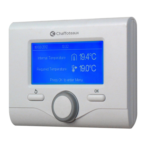
product description Buttons and Display: 1. back button (previous screen) 2. knob button (to confi rm operation or access main menu) 4. DISPLAY Display symbols: Summer ) Winter Heating only OFF, system off ) Time program ) Manual operation Flame present indication Desired room temperature Room temperature detected Desired room temperature override... -
Page 65: Initial Start-Up
Solar-electric indirect cylinder Solar collector Circulation pump Initial start-up Heat exchanger The fi rst time the EXPERT CONTROL system interface is connected, the user is required Diverter valve to choose certain basic settings. S1) Collector sensor First, you will need to select the user inter- S2) Low indirect cylinder sensor face language. -
Page 66: Display Settings
display settings The main page of the system interface can be customised. From the main page it is possible to check the time, date, operating mode, set or de- tected temperatures, hourly time schedule, the active energy sources and reduction of emissions (where present). -
Page 67: Home Screen
display settings press the OK button, select auto or man- the display during standby periods. ual, press the OK button. Press the OK button to confi rm. Press OK to confi rm the choice, and press Turn the knob and select: the back button "... -
Page 68: Heating System Operating Mode
heating system operating mode Press OK: the display visualises: - Time program / Manual - Summer / Winter / Off - Complete menu Turn the knob and select: - Summer / Winter / Off Press the OK button. Turn the knob and select: ) SUMMER production of domestic hot water, hea- ting excluded. -
Page 69: Room Temperature Adjustment
Press the back button “ “ to exit adjust- ment without saving the changes. The EXPERT CONTROL system interface will maintain the temperature value until the end of the set time period, when the pre-set room temperature is restored. -
Page 70: Heating Hot Water Settings
heating hot water setting To access the heating settings, press the OK button. Turn the knob and select: - Complete menu Press the OK button. Turn the knob and select: - CH settings Press the OK button. To set the fl ow temperature, turn the knob and select: - CH Setpoint temperature Press the OK button. -
Page 71: Heating Schedule Programming
heating schedule programming The Time program schedule allows for hea- Turn the knob and adjust the room tempera- ting the environment according to need. ture value during the comfort period (the temperature value will fl ash on the display). Press OK to set heating schedule program- Press the OK button to confi... -
Page 72: Preset Programs
heating schedule programming Turn the knob and select: - Modify to change any previously programmed periods Turn the knob and select: - Exit to exit schedule programming. Press the OK button to confi rm. The display reverts to showing the previous screen. - Page 73 heating schedule programming - Set time program Press the OK button. Turn the knob and select among the follow- ing: - Family program - No lunch program - Midday program - Always active Press the OK button to confi rm. Turn the knob to scroll through the days and the heating program start and end time.
-
Page 74: Manual Heating Mode
manual heating mode Manual mode disables heating schedule pro- gramming. Manual operation allows the heating to be kept on constantly. To select the manual mode for the heating function, press OK, turn the knob and select: - Time program / Manual Press the OK button. -
Page 75: Domestic Hot Water Settings
domestic hot water settings Press the OK button. Turn the knob and select: - Complete menu Press the OK button. Turn the knob and select: - DHW Settings Press the OK button. Turn the knob and select: - DHW comfort setpoint temp Press the OK button twice. -
Page 76: Domestic Hot Water Schedule Programming
domestic hot water schedule programming Turn the knob and select: - Set time program - Complete menu Press the OK button. To set the program- Press the OK button. ming, follow the procedure described in the chapter "heating schedule programming", Turn the knob and select: pre-set programs paragraph. -
Page 77: Additional Functions
additional functions To set the programme for one of the addi- will return to the previous visualisation. tional functions, press OK. In the active sources page, when the Auto Turn the knob and select: function is active the “SRA” icon appears. - Complete menu Press the OK button. -
Page 78: System Performance
system performance With a boiler or system, the following energy The energy consumption measurement performance values can be viewed. system integrated in this product is based on an estimate. Therefore, there Press the OK button. may be differences between the actual Turn the knob and select: consumption (or that measured by ano- - Complete Menu... -
Page 79: Installation
Before fi tting the appliance, make sure the electricity supply is not connected. Wall installation The Expert Control system interface must fi g. 2 be fi tted to the wall before the BUS line is connected. - connect the pair of wires to the connector (fi... - Page 80 installation Connection to the boiler The sending, receiving and decoding of sig- nals occurs through the BridgeNet® BUS protocol, which puts the boiler and the sys- tem interface in contact with each other. - connect a pair of wires to the BUS con- nector on the boiler P.C.B.
-
Page 81: Technical Area
technical area - Service Warning - Faults To guarantee safety and correct opera- tion of the system interface, it must be Turn the knob and select: commissioned by a qualifi ed technician - Bus network settings in possession of the skills as required by The display will show the list of devices con- law. -
Page 82: Confi Guration Wizard
technical area Zone 4 Parameters Press the OK button. Zone 5 Parameters Turn the knob and scroll through the param- Zone 6 Parameters eters to be set: HP System Parameters - Gas parameters Connectivity - Setting - Visualization Select the relevant menu and press the OK - Zone button. -
Page 83: Confi Guration Parameters
technical area Press the OK button. Press the back button “ “ twice to return Turn the knob and scroll the parameters to to the previous visualisation. be set: Turn the knob and select: - Service Center Data - Enable service warnings FAULTS - Service warning reset Press the OK button. -
Page 84: Temperature Adjustment
temperature adjustment To set the temperature adjustment parame- - low temperature system ters, simultaneously press and hold the back (fl oor panels) curve between 0.2 and 0.8 “ “ and “OK” buttons until "Enter code" ap- - high temperature system pears on the display. -
Page 85: Minimum Temperature
temperature adjustment a correction which is usually made to the Turn the knob and select: fl ow temperature in this type of system, 4.2.6 Minimum temperature during climatic adjustment. Press the OK button. Turn the knob and set the most suitable val- Turn the knob and select: ue, then press the OK button. -
Page 86: Menu Settings
menu - settings DESCRIPTION RANGE NOTE NETWORK BUS network Boiler System interface Solar Controller Solar Controller Cascade Manager Energy Manager Hybrid Energy Manager Heat Pump Heat Pump Room Sensor Zone Manager Remote Modem Network presence Multi Function Clip Fresh Water Station Swimming Pool Control Master User Interface Multi-room Control... - Page 87 menu - settings DESCRIPTION RANGE NOTE Tipologia circolatore caldaia Settings Soft ignition High modulation ratio ON - OFF 0. Disabled Fan modulation 1. Enabled 0. Floor Floor or 2nd Room Thermostat 1. Room 0. Absent Thermoregulation 1. Present 0. Disabled 1.
- Page 88 menu - settings DESCRIPTION RANGE NOTE 0. Low speed Pump Speed Control 1. High speed 2. Modulating Delta T Pump Set Central Heating-2 Min Pressure Warning Pressure Filling Pressure Post Ventilation CH OFF - ON Boost Time Max PWM Pump Min PWM Pump 0.
- Page 89 menu - settings DESCRIPTION RANGE NOTE Domestic hot water Diverter valve control Heating DHW Pump control ON - OFF Additional Output Control ON - OFF Additional Output Control 2 ON - OFF Test & Utilities Test mode ON - OFF Air-purge function ON - OFF Reset Menu...
- Page 90 menu - settings DESCRIPTION RANGE NOTE Solar Settings 2 Flow Rate Setting Digital solar group ON - OFF Pressure sensor active ON - OFF Pro-Tech anode active ON - OFF 0. Integration request Auxiliary output setting 1. Alarm 2. De-stratifi cation pump Target deltaT for pump modulation Thermal Cleance Cycle frequency Thermal Cleanse target temp...
- Page 91 menu - settings DESCRIPTION RANGE NOTE 0. Not defi ned 1. 150 l Tank capacity 2. 200 l 3. 300 l Showers n° Tank fi ll rate Error History Last 10 Errors Reset Error List Reset? OK=Yes, esc=No Reset menu Restore default settings ZONE 1 PARAMETERS Setpoint...
- Page 92 menu - settings DESCRIPTION RANGE NOTE 0. Radiator Fast 1. Radiator Medium 2. Radiator Slow Heating circuit type 3. Floor Heating Fast 4. Floor Heating Medium 5. Floor Heating Slow 6. Proportional only Max Integral Action on Room Control Z1 Diagnostics Room T Room T setpoint Flow temperature...
- Page 93 menu - settings DESCRIPTION RANGE NOTE T Night T set Z2 Zone frost temperature T Day Cool Free parameters Zone free parameter Zone free parameter Zone free parameter Z2 Settings 0. Low temperature Zone 2 temperature range 1. High temperature 0.
- Page 94 menu - settings DESCRIPTION RANGE NOTE 0. Fixed speed Zone Pump Modulation 1. Modulating on delta T 2. Modulating on pressure Target delta T for modulation Fixed pump speed Cooling T Set Cool Z2 Fan Coil Zone 2 Cooling Temp Range Underfl...
- Page 95 menu - settings DESCRIPTION RANGE NOTE 1. Fix Flow T 2. Basic Thermoreg Thermoregulation 3. Room T Only 4. Outdoor T Only 5. Room + Outdoor T Slope Offset Room Infl uence Proportional Max T Min T Radiator Fast Radiator Medium Radiator Slow Heating circuit type Floor Heating Fast...
- Page 96 menu - settings DESCRIPTION RANGE NOTE Offset Room Infl uence Proportional Max T Min T Target deltaT for pump modulation ZONE MODULE Manual mode ZM Manual mode activation ON - OFF Z1 pump control ON - OFF Z2 pump control ON - OFF Z3 pump control ON - OFF...
- Page 97 menu - settings DESCRIPTION RANGE NOTE Z5 pump control ON - OFF Z5 pump control ON - OFF 0. OFF Z5 Mix Valve Control 1. Open 2. Closed 0. OFF Z6 Mix valve control 1. Open 2. Closed General Zone Module 2 0.
- Page 98 menu - settings DESCRIPTION RANGE NOTE Boiler circulator cycles No. (n x10) Boiler Life Time (h x10) Time of fan ON (h x10) Fan cycles No. (n x10) CH fl ame detection No. (n x10) DHW fl ame detection No. (n x10) Boiler Statistics -2 Hours Burner On CH (h x10) Hours Burner On DHW (h x10)
- Page 99 menu - settings DESCRIPTION RANGE NOTE Storage Storage Meas T Solar Collect T DHW Inlet T NTC Storage Low Storage Setpoint-Stratifi cation Service Months to Next Maintenance Mainten On Days Act ON - OFF Maint Warn Reset Cancel? OK=Yes, esc=No 0.
- Page 100 menu - settings DESCRIPTION RANGE NOTE Quiet Mode Activation ON - OFF Quiet Mode start time [hh:mm] Quiet Mode end time [hh:mm] Not active Photovoltaic Integration Active PV Delta T DHW setpoint temp. Energy manager parameter 1 None Hydraulic scheme WHB Combi WHB + Tank FlowT HP Offset...
- Page 101 menu - settings DESCRIPTION RANGE NOTE Time for prerun new attempt CH Pump Overrun Low speed Pump Speed Control High speed Modulating Delta T Pump Setpoint Min Pressure Warning Pressure Max PWM Pump Min PWM Pump Floor drying Flow Set Point T Cooling Not active Cooling mode activation...
- Page 102 menu - settings DESCRIPTION RANGE NOTE Diverter valve control Diverter valve COOLING COOLING Auxiliary circulator ON - OFF Output AUX 1/2 contact ON - OFF Force Hp Heat ON - OFF Force Hp Cool ON - OFF Force WHB MAX CH MAX DHW Anode output ON - OFF...
- Page 103 menu - settings DESCRIPTION RANGE NOTE kWh cost from Boiler Estimated Energy Manager free parameter Energy Manager free parameter HP Diagnostics - 1 Outside air temperature HP water fl ow temp HP water return temp HP Evaporator temp HP Suction temp HP Discharge temp HP condenser outlet temp OPEN...
- Page 104 menu - settings DESCRIPTION RANGE NOTE Stand-by Antifreeze Cycle Heating Cycle DHW Cycle Thermal Cleanse Function Air Purge Function Chimney Function Energy Manager Status Floor Drying Cycle No Heat Generation Manual Mode Error Initialization Cool Mode CH Flow Set T CH Flow Temperature CH Return Temperature DHW Storage Temperature...
- Page 105 menu - settings DESCRIPTION RANGE NOTE Reset Menu Reset Factory Settings Boiler FRESH WATER STATION User Parameters DHW Setpoint Temperature 10 1 Manual Mode Manual mode activation ON - OFF Loading pump activation ON - OFF Diverter valve activation ON - OFF Aux 1 activation ON - OFF Stepper Mix Control...
- Page 106 menu - settings DESCRIPTION RANGE NOTE Not defi ned 3 direct zones Lockout and reset manager Function selection Generic differential thermostat Generic thermostat Time programmed output Heat metering output Manual mode activation ON - OFF OUT1 control ON - OFF OUT2 control ON - OFF OUT3 control...
- Page 107 menu - settings DESCRIPTION RANGE NOTE 14 1 Free Zone general parameter Zone general parameter Zone free parameter 14 2 Z4 Settings Low Temp Zone 4 temperature range High Temp Fix Flow T Basic Thermoreg Thermoregulation Room T Only Outdoor T Only Room+Outdoor T Slope Offset...
- Page 108 menu - settings DESCRIPTION RANGE NOTE Pump fi xed speed Zone5 Parameters Setpoint T Day T Night T set Z5 Zone frost temperature 15 1 Free Zone free parameter Zone free parameter Zone free parameter 15 2 Z5 Settings Low Temp Zone 5 temperature range High Temp Fix Flow T...
- Page 109 menu - settings DESCRIPTION RANGE NOTE Heat Request Z5 ON - OFF Pump status ON - OFF 15 4 Z5 Zone Module Settings 0. Fixed speed Zone Pump Modulation 1. Modulating on delta T 2. Modulating on pressure Target deltaT for pump modulation Pump fi...
- Page 110 menu - settings DESCRIPTION RANGE NOTE 16 3 Z6 Diagnostics Room T Room T Setpoint Flow temperature Return temperature Heat Request Z6 ON - OFF Pump status ON - OFF 16 4 Z6 Zone Module Settings 0. Fixed speed Zone pump modulation 1.
- Page 111 menu - settings DESCRIPTION RANGE NOTE None Fault alarm AUX Output 1 (AFR) Humidistat alarm External heat request None Fault alarm AUX Output 2 Humidistat alarm External heat request Auxiliary circulator AUX P2 circulator setting Cooling circulator 17 2 Energy manager parameter 1 None Plus Hydraulic scheme...
- Page 112 menu - settings DESCRIPTION RANGE NOTE Delta T Pump Setpoint Min Pressure Warning Pressure Max PWM Pump Min PWM Pump 17 4 Cooling Cooling mode activation Not active Active 17 5 Domestic Hot Water DHW Comfort Setpoint T DHW Reduced Set Point T Disabled Time based Always Active...
- Page 113 menu - settings DESCRIPTION RANGE NOTE Force Hp Cool ON - OFF Rating Heating Mode ON - OFF Rating Cooling Mode ON - OFF Compressor frequency setting Fan 1 rpm setting Fan 2 rpm setting TDM Aux output 17 8 TEST &...
- Page 114 menu - settings DESCRIPTION RANGE NOTE HP Suction temp HP Discharge temp HP condenser outlet temp Aux Temperature 17 11 HP Diagnostics - 2 Stand by Cooling Heating Booster Heating Booster Cooling Rating Heating Mode Heat Pump Mode Rating Cooling Mode Freeze Protection Defrost High Temperature Protection...
- Page 115 menu - settings DESCRIPTION RANGE NOTE Expansion valve Valve - Pressure Equalizer 17 13 HP Diagnostics - 4 compressor on/off compressor preheating current fan 1 status current fan 2 status 4way valveheat/cool Base Panel Heater Status Compressor phase current EM Diagnostics - 1 Input Stand-by Antifreeze Cycle Heating Cycle...
- Page 116 menu - settings DESCRIPTION RANGE NOTE CH Circulator Status ON - OFF HC Pump 2 ON - OFF Diverter Valve (CH/DHW) Diverter Valve 2 (CH/Cooling) COOLING CH Backup Resistance 1 ON - OFF CH Backup Resistance 2 ON - OFF CH Backup Resistance 3 ON - OFF Not active...
- Page 117 menu - settings DESCRIPTION RANGE NOTE Not provisioned Active Status Provisioned - Not active Active Serial Number Initialization Waiting for Update SW Upgrade Status Updating Micro 1 Updating Micro 2 Reset Menu Factory Reset (Soft Reset) Reset? OK=Yes,esc=No...
-
Page 118: Table Of Error Codes
table of error codes ERROR DESCRIPTION ERROR DESCRIPTION 1 01 Overheat 2 13 SM NTC Collector Out Damaged 1 02 Pressure Sens Error 2 14 SM Undefi ned Hydraulic Scheme 1 03 Flow Check Failed 2 15 SM Pressure Sensor Disconnected 1 04 Flow Check Failed 2 16... - Page 119 table of error codes ERROR DESCRIPTION ERROR DESCRIPTION 4 03 Sim Card error 6 P4 Low fan speed 4 04 Mdm-PCB Com err 7 01 Zone1 Send Probe Damaged 4 05 Mdm In1 error 7 02 Zone2 Send Probe Damaged 4 06 Mdm In2 error 7 03...
-
Page 120: Microswitch
table of error codes type of shutdown and the reason behind it. ERROR DESCRIPTION To restore normal operation, follow the in- Freeze error, LWT and/or TR too low. 9 17 structions provided on the display or, if the Service reset to remove fault error persists, contact an authorised Techni- 9 18 Pump Down Error... - Page 121 table des matières généralités …………………………………………………………………………………………………… 121 consignes de sécurité ………………………………………………………………………………… 123 caractéristiques techniques ……………………………………………………………………… 124 description du produit ………………………………………………………………………………… 125 réglage de l'affi cheur …………………………………………………………………………………… 127 mode de fonctionnement chauffage ………………………………………………………… 129 réglage température ambiante ………………………………………………………………… 130 réglage eau chaude chauffage …………………………………………………………………… 131 programmation horaire chauffage ……………………………………………………………...
-
Page 122: Généralités
L’interface système EXPERT CONTROL per- met une gestion simple et effi cace de la température des différents espaces et de l’eau chaude sanitaire. Il vous fournit également les premières pistes en cas de dysfonctionnement du système installé en signalant le type d’anomalie et en proposant la marche à... -
Page 123: Consignes De Sécurité
consignes de sécurité LÉGENDE DES SYMBOLES : capacités physiques, sensorielles ou mentales sont réduites ou qui ne disposent pas des Le non-respect des avertissements com- connaissances ou de l'expérience nécessaires, porte un risque de lésions et peut même à moins qu'elles n'aient été formées et enca- dans certains cas entraîner la mort. -
Page 124: Caractéristiques Techniques
FICHE PRODUIT Nom du fournisseur Chaffoteaux Nom de modèle du fournisseur Expert Control Classe de contrôle de la température Contribution à l'effi cacité énergétique en % pour le chauff age des pièces En ajoutant une sonde extérieure : Classe de contrôle de la température Contribution à... -
Page 125: Description Du Produit
description du produit Touches et Affi cheur : 1. touche Retour (affi chage précédent) 2. bouton 3. touche (confi rmer l’opération ou accéder au menu principal) 4. AFFICHEUR Légende symboles affi cheur : Été ) Hiver OFF système éteint ) Chauffage programmé ) Chauffage manuel Indication présence de fl... - Page 126 description du produit Symboles visibles avec système solaire )Confort sanitaire en période faible et/ou pompe à chaleur : débit et à un point de consigne réduite à 40 ° C au cours de la ) Chaudière période plein tarif ) Mise en fonction BOOST ) Rafraîchissement ) Mode réduit PAC...
-
Page 127: Réglage De L'affi Cheur
réglages de l'affi cheur L'affi chage principal de la commande à dis- tance peut être personnalisé. L'affi chage principal permet de contrôler l'heure, la date, le mode de fonctionnement de la chaudière, les températures réglées ou détectées par l'interface de système, la programmation horaire, les sources d'énergie actives (si pré- sentes) et la réduction des émissions de CO Pour accéder aux confi... -
Page 128: Contraste
réglages de l'affi cheur Appuyez sur la touche OK pour vali Tournez le bouton et sélectionnez : der. - Tempo. rétro éclairage Tournez le bouton et sélectionnez l'heure réglez à l'aide du bouton le temps de ré- légale, appuyez sur la touche OK, sélec- tro-éclairage de l'affi... -
Page 129: Mode De Fonctionnement Chaudière
mode de fonctionnement chaudière Pour sélectionner le mode de fonctionne- ment de la chaudière appuyez sur la touche L’affi cheur signale : - Mode Programmé ou Manuel - Eté / Hiver / OFF - Menu Tournez le bouton et sélectionnez : - Été... -
Page 130: Réglage Température Ambiante
“ pour sor- tir du réglage sans enregistrer la modifi ca- tion. L’interface de système EXPERT CONTROL maintiendra la valeur de température jusqu'à la fi n du temps sélectionné, à la fi n duquel il reviendra à la température ambiante présé- lectionnée. -
Page 131: Réglage Eau Chaude Chauffage
réglage eau chaude chauffage Pour accéder aux réglages chauffage, ap- puyez sur la touche OK. Tournez le bouton et sélectionnez : - Menu Appuyez sur la touche OK. Tournez le bouton et sélectionnez : - Réglage chauffage Appuyez sur la touche OK. Pour régler la température de départ, tour- nez le bouton et sélectionnez : - Température départ chauffage... -
Page 132: Programmation Horaire Chauffage
programmation horaire chauffage La programmation horaire permet de ré- Appuyez sur la touche OK. chauffer l’espace selon les exigences. Tournez le bouton et modifi ez la valeur de température ambiante pendant la période Pour sélectionner la programmation horaire confort (la valeur de la température est affi - de chauffage appuyez sur la touche OK. -
Page 133: Programmation Guidée
programmation horaire chauffage - Jours restants en cas de jours pas encore programmés et refaites les opérations décrites précé- demment Tournez le bouton et sélectionnez : - Modifi er pour modifi er toute période programmé précédemment Tournez le bouton et sélectionnez : - Quitter pour sortir du réglage de la programma- tion horaire. -
Page 134: Gestion Des Zones
programmation horaire chauffage horaire. Appuyez sur la touche OK. Tournez le bouton et sélectionnez - Réglage créneaux horaires Appuyez sur la touche OK. Tournez le bouton et sélectionnez : - Programme famille - Programme sans déjeuner - Programme midi - Toujours actif Appuyez sur la touche OK pour valider. -
Page 135: Fonctionnement Mode Manuel Chauffage
fonctionnement mode manuel chauffage Le mode manuel, désactive la programma- tion horaire de chauffage. Le fonctionnement manuel, permet de maintenir le chauffage en continu. Pour activer le mode manuel pour le chauf- fage, appuyer sur la touche OK tourner le bouton et sélectionner: - Mode Programmé... -
Page 136: Réglage Eau Chaude Sanitaire
réglage eau chaude sanitaire Appuyez sur la touche OK. Tournez le bouton et sélectionnez : - Menu Appuyez sur la touche OK. Tournez le bouton et sélectionnez : - Réglages ECS Appuyez sur la touche OK. Tournez le bouton et sélectionnez : - Température COMFORT ECS Appuyez deux fois sur la touche OK. -
Page 137: Programmation Horaire Eau Chaude Sanitaire
programmation horaire eau chaude sanitaire Pour sélectionner la programmation horaire duction instantanée d’eau chaude avec d’eau chaude sanitaire appuyez sur la touche pompe de recirculation de l’eau chaude sanitaire, électrosolaire) Tournez le bouton et sélectionnez Dans les deux cas, tournez le bouton et - Menu réglez la température confort et réduite, Appuyez sur la touche OK. -
Page 138: Fonctions Supplémentaires
fonctions supplémentaires Pour défi nir le programme d’une fonction - ON (active la fonction) supplémentaire, appuyer sur OK. - OFF (désactive la fonction) Tournez le bouton et sélectionnez Appuyer sur OK pour enregistrer les réglages. - Menu L’écran précédent s’affi che. Appuyez sur la touche OK. -
Page 139: Performances Du Système
performances du système En présence d’une chaudière ou d’un sys- 4 derniers mois, en kW/h, en mode eau tème, il est possible de visualiser les perfor- chaude sanitaire, chauffage et refroidisse- mances énergétiques suivantes. ment Tournez le bouton et sélectionnez CONSOMMATIONS ÉNERGÉTIQUES - Menu Le système de mesure des consomma-... -
Page 140: Installation
Installation murale fi g. 2 Il faut procéder à la fi xation murale de l'inter- face de système Expert Control avant d'ef- fectuer le raccordement à la ligne BUS. Il faut procéder à la fi xation murale de l’inter- face système Sensys avant d’effectuer le raccordement à... - Page 141 installation Raccordement à la chaudière L'envoi, la réception et le décodage des si- gnaux se font par le biais du protocole BUS BridgeNet® qui assure les échanges entre la chaudière et l'interface de système. - raccordez une paire de fi ls au connecteur BUS sur la carte de la chaudière - raccordez la paire de fi...
-
Page 142: Menu Technicien
menu technicien - Paramétrage guidé Attention - Maintenance Pour garantir la sécurité et le bon fonc- - Anomalies tionnement de l’interface de système, sa mise en service doit être effectuée par Tournez le bouton et sélectionnez : un professionnel qualifi é remplissant les - RÉGLAGES RÉSEAU BUS conditions requises par la loi. -
Page 143: Paramétrage Guidé
menu technicien 13 Free (permet l’affi chage et le réglage des para- 14 Par. Zone Chauffage 4 mètres essentiels au bon fonctionnement de 15 Par. Zone Chauffage 5 la chaudière) Appuyez sur la touche 16 par. Zone chauffage 6 17 Parametré systeme pac Tournez le bouton et faites défi... - Page 144 menu technicien nées du centre d’assistance technique et les Appuyez sur la touche OK pour valider. avis d’entretien) Appuyez sur la touche retour « » pour Appuyer sur la touche OK. revenir à l’affi chage précédent. Tourner le bouton et parcourir les para- mètres à...
-
Page 145: Réglage Zone 1
thermorégulation Pour entrer les paramètres de régulation ther- - installation basse température mique appuyez simultanément sur les touches (panneaux au sol) Pente de 0,2 à 0,8 Retour " " et "OK" jusqu'à l'affi chage de l'op- - installation haute température tion "Insérer code". -
Page 146: Thermorégulation
thermorégulation différence du point d'origine des courbes qui appropriée et appuyez sur la touche OK pour la haute température est de + 10°C, cor- rection qui est appliquée d'habitude à la tem- Tournez le bouton et sélectionnez : pérature de départ de ce type d'installations, 4.2.6 Réglage T°... -
Page 147: Menu Réglages
menu - réglages DESCRIPTION SÉLECTION NOTES RÉSEAU RÉSEAU BUS Chaudière Commande à distance Contrôleur solaire Contrôleur solaire Manager Cascade Energy Manager Energy Manager Hybride Pompe à chaleur Pompe à chaleur Sonde d’ambiance Contrôleur multi-zone Modem à distance Présence réseau Carte multi fonction Préparateur ECS (FWS) Contrôleur piscine Commande à... - Page 148 menu - réglages DESCRIPTION SÉLECTION NOTES Allumage lent Modulation gaz 1/10 ON - OFF 0. Désactivée Modulation du ventilateur 1. Active 0. Thermostat de sécurité plancher Thermost. plancher ou TA zone 2 1. Thermostat ambiance zone2 0. Désactivée Thermorégulation [SRA] 1.
- Page 149 menu - réglages DESCRIPTION SÉLECTION NOTES PAR. CHAUFFAGE - PART 2 Pression mini circuit chauffage Seuil d'alerte pression basse Pression de remplissage OFF [5 secondes] Post-ventil. après demande CH ON [3 minutes] Tempo. BOOST chauffage % puissance maxi pompe % puissance mini pompe 0.
- Page 150 menu - réglages DESCRIPTION SÉLECTION NOTES Fonction contrôle de combustion ON - OFF Cycle de purge installation ON - OFF MENU RESET Rétablir réglages usine OK = Oui, esc = Non BALLON & SOLAIRE REGLAGE GENERAL BALLON Réglage T° COMFORT ballon Réglage T°...
- Page 151 menu - réglages DESCRIPTION SÉLECTION NOTES 0. Contact de sortie Réglage sortie auxiliaire 1. Alarme 2. Pompe de destratifi cation Delta T° modulation pompe Fréquence fonction anti-bactérie T° consigne fonction anti-bactérie Paramètre générique solaire Paramètre générique solaire PILOTAGE MANUEL SOLAIRE Activation pilotage manuel ON - OFF Pilotage pompe solaire...
- Page 152 menu - réglages DESCRIPTION SÉLECTION NOTES PAR. ZONE CHAUFFAGE 1 REGLAGE TEMPERATURE Température chauffage Confort Température chauffage Eco Température départ CH zone 1 Température hors gel zone 1 PARAMETRES GENERIQUES Paramètre générique zone Paramètre générique zone Paramètre générique zone REGLAGE ZONE 1 0.
- Page 153 menu - réglages DESCRIPTION SÉLECTION NOTES 0. Vitesse fi xe Type de pompe 1. Auto adaptatif sur Delta T° 2. Auto adaptatif sur pression Delta T° pour modulation pompe Vitesse constante pompe Rafraîchissement Consigne T° rafraîchiss. zone 1 Ventilo convecteur Type circuit rafr zone 1 Plancher Thermostat ON/OFF...
- Page 154 menu - réglages DESCRIPTION SÉLECTION NOTES Compensation d'ambiance Réglage T° max CH zone 2 Réglage T° min CH zone 2 0. Radiateur faible inertie 1. Radiateur moyenne inertie 2. Radiateur haute inertie Type émetteur chauffage 3. Plancher chauffant faible inertie 4.
- Page 155 menu - réglages DESCRIPTION SÉLECTION NOTES Température chauffage Confort Température chauffage Eco Température départ CH zone 3 Température hors gel zone 3 PARAMETRES GENERIQUES Paramètre générique zone REGLAGE ZONE 3 0. Basse température Type circuit chauffage zone 3 1. Haute température 0.
- Page 156 menu - réglages DESCRIPTION SÉLECTION NOTES Rafraîchissement Consigne T° rafraîchiss. zone 3 Ventilo convecteur Type circuit rafr zone 3 Plancher Thermostat ON/OFF Sélection type thermorégulation Température départ fi xe Sonde externe seule Pente de thermorégulation Décallage parallèle de pente Compensation d'ambiance Réglage T°...
- Page 157 menu - réglages DESCRIPTION SÉLECTION NOTES Paramètre générique multizone Paramètre générique multizone PILOTAGE MANUEL MODULE N°2 Activation pilotage manuel ON - OFF Pilotage pompe zone 4 ON - OFF Pilotage pompe zone 5 ON - OFF Pilotage pompe zone 6 ON - OFF 0.
- Page 158 menu - réglages DESCRIPTION SÉLECTION NOTES STATISTIQUE -1 Nb cycles vanne distributrice [n x10] Durée fonctionnement pompe [h x10] Nb cycles pompe chaudière [n x10] Durée de fonctionnement chaudière [h x10] Durée de fonctionnement ventilateur [h x10] Nb cycles ventilateur [n x10] Nb détection fl...
- Page 159 menu - réglages DESCRIPTION SÉLECTION NOTES Température extérieure T° BALLON & SOLAIRE Température ballon T° collecteur solaire T° entrée sanitaire solaire T° sonde basse ballon T° consigne ballon stratifi é ASSISTANCE TECHNIQUE Nb mois avant prochain entretien Activer avertissement entretien ON - OFF RAZ avertissement d’entretien Effacer ? OK=Oui esc=Non...
- Page 160 menu - réglages DESCRIPTION SÉLECTION NOTES Début mode nuit PAC [hh:mm] Fin mode nuit PAC [hh:mm] Désactivé Integration PV Actif PV delta T° ECS ENERGY MANAGER - PARTIE 1 Non défi ni Schema hydraulique Chaudière mixte Chaudière + ballon Correction température départ PAC T°...
- Page 161 menu - réglages DESCRIPTION SÉLECTION NOTES Delta T° pour modulation pompe Pression mini circuit chauffage Seuil d'alerte pression basse % puissance maxi pompe % puissance mini pompe Consigne T° séchage de dalle Rafraîchissement Désactivé Activation mode Rafraîchissement Actif Anticyclage Rafraîchissement Correction T°...
- Page 162 menu - réglages DESCRIPTION SÉLECTION NOTES Puissance mini Fonction contrôle de combustion Puissance maxi chauffage Puissance maxi sanitaire Anode ON - OFF PARAMETRE CHANTIER Cycle de purge installation ON - OFF Montée en T° maximale Montée en T° progressive Séchage de dalle Montée en T°...
- Page 163 menu - réglages DESCRIPTION SÉLECTION NOTES Ouvert Température sortie condenseur PAC Fermé Statut débistat Fréquence compresseur PAC Puissance compresseur PAC DIAGNOSTIC PAC - 2 Stand by Rafraîchissement Chauffage Mode PAC Hors gel Dégivrage Protection haute température Timeguard Erreur du système PAC erreur EM Diagnostics - 1 Input stand-by...
- Page 164 menu - réglages DESCRIPTION SÉLECTION NOTES Statut circulateur circuit primaire ON - OFF Statut circulateur auxiliaire ON - OFF Position sanitaire VVanne 3 voies (CH/ECS) Position chauffage Position chauffage Vanne 3 voies (CH/RAFR) Position rafraîchissement Désactivé Anode Actif Historique Des Anomalies 10 dernières anomalies Rétablir réglages usine OK = OUI / ESC = NON...
- Page 165 menu - réglages DESCRIPTION SÉLECTION NOTES Température sonde basse ballon Consommation ECS totale Heures marche pompe de charge CARTE MULTIFONCTION GENERAL Non défi ni 3 zones directes Notifi er erreurs et reset Sélection de la fonction Thermostat différentiel Thermostat Sortie temporisée Contact mode ECS Pilotage manuel ON - OFF...
- Page 166 menu - réglages DESCRIPTION SÉLECTION NOTES Température chauffage Eco Température départ CH zone 4 Température hors gel zone 4 PARAMETRES GENERIQUES Paramètre générique zone REGLAGE ZONE 4 0. Basse température Type circuit chauffage zone 4 1. Haute température 0. Température départ fi xe 1.
- Page 167 menu - réglages DESCRIPTION SÉLECTION NOTES Température chauffage Confort Température chauffage Eco Température départ CH zone 5 Température hors gel zone 5 PARAMETRES GENERIQUES Paramètre générique zone Paramètre générique zone Paramètre générique zone REGLAGE ZONE 5 Basse température Type circuit chauffage zone 5 Haute température Température départ Fixe Thermostat ON/OFF...
- Page 168 menu - réglages DESCRIPTION SÉLECTION NOTES DeltaT objectif pour modulation Delta T° pour modulation pompe Vitesse fi xe pompe Vitesse constante pompe PAR. ZONE CHAUFFAGE 6 REGLAGE TEMPERATURE Température chauffage Confort Température chauffage Eco Température départ CH zone 6 Température hors gel zone 6 PARAMETRES GENERIQUES Paramètre générique zone REGLAGE ZONE 6...
- Page 169 menu - réglages DESCRIPTION SÉLECTION NOTES Vitesse fi xe Type de pompe Auto adaptatif sur Delta T° Auto adaptatif sur pression Delta T° pour modulation pompe Vitesse constante pompe PARAMETRÉ SYSTEME PAC PARAMETRE UTILISATEUR 0. Mode Green Mode chauffage 1. Mode Standard Activer mode nuit PAC ON - OFF Début mode nuit PAC [hh:mm]...
- Page 170 menu - réglages DESCRIPTION SÉLECTION NOTES Désactivée Thermorégulation Activée ECO PLUS Modalité de fonctionnement CH MOYEN COMFORT COMFORT PLUS Correction température départ PAC Tempo. BOOST chauffage Correction température extérieure 0 étage 1 étage Réglage résistance électrique 2 étages 3 étages Statut anode Pro-Tech ON - OFF Confi...
- Page 171 menu - réglages DESCRIPTION SÉLECTION NOTES Désactivée Temporisée Toujours active Fonction COMFORT Heures creuses - Heures pleines Heures creuses - Heures pleines - 40°C Mode Green Temps max PAC seule Fonction anti-bactérie ON - OFF Départ cycle anti-bactérie [hh:mm] PILOTAGE MANUEL - 1 Activation pilotage manuel ON - OFF Pilotage circuit primaire...
- Page 172 menu - réglages DESCRIPTION SÉLECTION NOTES Montée en T° maximale Montée en T° progressive Séchage de dalle Montée en T° maximale puis progressive Montée en T° progressive puis maximale Manuel Total jours restants séchage Jours restants séchage chauffage fonctionnel Jours restants séchage chauffage prêt STATISTIQUE ENERGY MANAGER Temps marche PAC [h/10] Nombre démarrages PAC [nb/10]...
- Page 173 menu - réglages DESCRIPTION SÉLECTION NOTES Stand by Rafraîchissement Chauffage Boost chauffage Boost rafraîchissement Chauffage forcé PAC - mode Labo Mode PAC Rafraîchissement forcé PAC- mode Labo Hors gel Dégivrage Protection haute température Timeguard Erreur du système Erreur système (RESET de service) Récupération fl...
- Page 174 menu - réglages DESCRIPTION SÉLECTION NOTES Statut condon chauffant unité extérieure Courant compresseur Statut report alarme 1 Statut sortie AUX TDM ON - OFF Entrée alarme (basse tension) Diagnostic EM - 1 entrées stand-by Hors gel chauffage sanitaire Fonction anti-bactérie Purge automatique Cheminée Séchage de dalle...
- Page 175 menu - réglages DESCRIPTION SÉLECTION NOTES Resistance back-up CH 2 ON - OFF Resistance back-up CH 3 ON - OFF Désactivé Anode Actif Ouvert Sortie AUX 1 (Alarme) Fermé Ouvert Sortie AUX 2 (AFR) Fermé HISTORIQUE DES ANOMALIES 10 dernières anomalies Reset des anomalies OK = OUI / ESC = NON MENU RESET...
- Page 176 DESCRIPTION SÉLECTION NOTES Reset paramètres usine Reiniciar OK= Si, Esc= No...
-
Page 177: Tableau Des Codes Erreurs
tableau des codes erreurs ERRORE DESCRIZIONE ERRORE DESCRIZIONE 1 01 Surchauffe du circuit primaire 2 10 Anomalie sonde haute ballon solaire 1 02 Erreur capteur de pression 2 11 Anomalie sonde retour CH solaire 1 03 Anomalie débit chauffage 2 12 Anomalie sonde entrée collecteur 1 04 Anomalie débit chauffage... - Page 178 tableau des codes erreurs ERRORE DESCRIZIONE ERRORE DESCRIZIONE 3 P9 Prévoir entretien. Contacter SAV 6 21 Erreur chaudière 4 01 Anomalie communication Mdm-Bus 6 P1 Retard pressostat air 4 02 Anomalie communication GPRS 6 P2 Ouverture pressostat air 4 03 Anomalie sur carte Sim 6 P4 Vitesse ventilateur faible...
- Page 179 tableau des codes erreurs ERRORE DESCRIZIONE ERRORE DESCRIZIONE Erreur sonde LWT Erreur confi guration du type de ventilateur PAC Erreur sonde TR Rétablissement fonctionnement Erreur communication Contrôleur Unité Extérieure En cas d'arrêt, sur l'affi cheur de l'interface de système on lit un code correspondant au Erreur TEO type d'arrêt et à...
- Page 180 inhoud algemeen ……………………………………………………………………………………………………… 189 veiligheidsnormen ………………………………………………………………………………………… 190 technische kenmerken ………………………………………………………………………………… 191 beschrijving product …………………………………………………………………………………… 192 instelling display …………………………………………………………………………………………… 194 modalità funzionamento riscaldamento …………………………………………………… 196 afstelling kamertemperatuur ……………………………………………………………………… 197 instelling warm water verwarming …………………………………………………………… 198 tijdsprogrammering verwarming ……………………………………………………………… 199 werking handmatige modus verwarming ………………………………………………… 202 instelling warm tapwater ……………………………………………………………………………...
-
Page 181: Algemeen
Met de systeeminterface EXPERT CONTROL kunt u de temperatuurregeling van de ka- mers en de controle van het warme tapwa- ter eenvoudig en doeltreffend beheren. Het is tevens de eerste hulp in geval van storingen van het geïnstalleerde systeem. -
Page 182: Veiligheidsnormen
veiligheidsnormen LEGENDA VAN DE SYMBOLEN: OPGELET! Het apparaat is niet bestemd voor gebruik door Het niet opvolgen van deze aanwijzingen personen (kinderen inbegrepen), die beperkte leidt tot risico van verwondingen van per- fysieke, gevoels- of mentale capaciteiten heb- sonen, die in bepaalde omstandigheden ben, of onvoldoende ervaring/kennis, behalve zelfs dodelijk kunnen zijn. -
Page 183: Technische Kenmerken
Resolutiegraad 0,1°C Product Fiche Naam fabrikant Chaffoteaux Modelnaam fabrikant Expert Control Klasse van de temperatuurregelaar Bijdrage aan jaarrendement voor verwarming in % Bij toevoegen van een buitenvoeler: Klasse van de temperatuurregelaar Bijdrage aan jaarrendement voor verwarming in % In een systeem met 3 groepen incl. 2 Stuks ruimte-units... -
Page 184: Beschrijving Van Het Product
beschrijving van het product Toetsen en Display: 1. toets Terug (vorige scherm) 2. draaiknop 3. toets (bevestig de handeling of ga naar het hoofdmenu) 4. DISPLAY Simbolen display: Zomer ) Winter OFF systeem uit ) Tijdsprogrammering ) Handmatige werking Aanwijzing aanwezigheid vlam Gewenste kamertemperatuur Waargenomen kamertemperatuur Gewenste kamertemperatuur afwijking... -
Page 185: Eerste Ontsteking
beschrijving van het product Symbolen die verschijnen bij zonnesysteem en/of Stille modus geïnstalleerde warmtepomp: Speciale functies Ketel Eerste Ontsteking ) Ketel in bedrijf De eerste keer dat de systeeminterface EX- Koeling PERT CONTROL wordt aangesloten, wordt u Vloerinstallatie gevraagd enkele basisinstellingen te kiezen. Het is allereerst noodzakelijk de taal van de Boiler met 1 serpentijn gebruikersinterface te selecteren. -
Page 186: Scherminstellingen
instellingen display Het beginscherm van de systeeminterface kan worden gepersonaliseerd. In het beginscherm is het mogelijk de tijd, de datum, de bedrijfsmodus van de ketel, de inge- stelde temperaturen of die waargenomen door de systeeminterface, de tijdsprogrammering, de actieve energiebronnen en de verlaging van de CO2-uitstoot (waar aanwezig) te controleren. - Page 187 instellingen display Draai aan de knop en selecteer zomer- display tijdens de stand-by periodes. tijd, druk op de toets OK, selecteer auto of Druk op de toets OK om te bevestigen. handmatig, druk op de toets OK. Draai aan de knop en selecteer: Druk op de toets OK om de keuze te bevestigen - Oplichten en druk op de toets Terug “...
- Page 188 werkingsmodus verwarming druk op de OK toets, op het display verschijnt: - Geprogrammeerd / Handmatig - Zomer / Winter / Off - Volledig menu Draai aan de knop en selecteer: - Zomer / Winter / Off Druk op de toets OK. Draai aan de knop en selecteer: ) ZOMER productie van warm tapwater, uitsluiting...
-
Page 189: Afstelling Kamertemperatuur
Druk op de toets terug “ “ om de afstelling te verlaten zonder de wijziging op te slaan. De interface van het EXPERT CONTROL-sy- steem handhaaft de temperatuurwaarde tot het einde van de ingestelde tijd, waarna deze terugkeert tot de vooraf ingestelde kamer- temperatuur. -
Page 190: Instelling Warm Water Verwarming
instelling warm water verwarming Druk op de toets OK om toegang te verkrijgen tot de instellingen van de verwarming. Draai aan de knop en selecteer: - Volledig menu Druk op de toets OK. Draai aan de knop en selecteer: - Instelling verwarming Druk op de toets OK. -
Page 191: Tijdsprogrammering Verwarming
tijdsprogrammering verwarming de (op het display wordt knipperend de tem- omgeving volgens uw eigen behoeften peratuurwaarde weergegeven). verwarmen. Druk op de toets OK om te bevestigen. Druk op de toets OK om de tijdsprogramme- ring van de verwarming in te stellen. Draai aan Draai aan de knop en selecteer - Stel T Reductie in de knop en selecteer -... -
Page 192: Vooraf Ingestelde Programma's
tijdsprogrammering verwarming Draai aan de knop en selecteer: - Wijzig om eventueel eerder geprogrammeerde periodes te wijzigen Draai aan de knop en selecteer: - Esc om de ingestelde tijdsprogrammering te verlaten. Druk op de toets OK om te bevestigen. Het display keert terug naar het vorige scherm. - Page 193 tijdsprogrammering verwarming Druk op de toets OK. Draai aan de knop en selecteer uit: - Programma familie - Programma ochtend - Programma lunch - Altijd actief Druk op de toets OK om te bevestigen. Draai aan de knop om de dagen en de begin- en eindtijd van het verwarmingsprogramma te doorlopen.
-
Page 194: Werking Handmatige Modus Verwarming
werking handmatige modus verwarming Met de handmatige modus wordt de tijdsprogrammering van de verwarming ge- deactiveerd. Met de handmatige werking kan de verwar- ming continu blijven werken. Druk op de OK toets om toegang te verkrijgen tot het Menu en de werking van de verwarming in handmatige modus te se- lecteren. -
Page 195: Instelling Warm Tapwater
instelling warm tapwater Druk op de toets OK. Draai aan de knop en selecteer: - Volledig menu Druk op de toets OK. Draai aan de knop en selecteer: - Instellingen Sanitair (warm tapwater) Druk op de toets OK. Draai aan de knop en selecteer: - Insteltemperatuur sanitair Druk twee keer op de toets OK. -
Page 196: Tijdsprogrammering Warm Tapwater
tijdsprogrammering warm tapwater ìDruk op de toets OK om de tijdsprogramme- op de toets OK om te bevestigen. ring van warm tapwater in te stellen. Draai aan de knop om te selecteren: Draai aan de knop en selecteer - Stel de programmering in - Volledig menu Druk op de toets OK. -
Page 197: Extra Functies
extra functies Druk op de OK toets om de programmering - ON (voor activering van de functie) van een van de extra functies in te stellen. - OFF (voor deactivering van de functie) Draai aan de knop en selecteer Druk op de toets OK om de instellingen op te - Volledig menu slaan, het display keert terug naar het vorige Druk op de toets OK. -
Page 198: Systeemprestaties (Indien Beschikbaar)
systeemprestaties Bij aanwezigheid van een installatie voor ENERGIEVERBRUIK zonne-energie, is het mogelijk de energie- Het meetsysteem van de geïntegreerde prestaties van het geïnstalleerde systeem energieverbruik in dit product is gebaseerd weer te geven. op een schatting. Er kan daarom verschillen tussen de werkelijke verbruik (of gemeten Draai aan de knop en selecteer door een ander systeem) en de één weer-... -
Page 199: Installatie
Voor de montage de spanning van de ke- tel wegnemen. Installatie aan de wand De muurbevestiging van de systeeminterface EXPERT CONTROL moet worden uitgevoerd vóór de aansluiting op de BUS-lijn. fi g. 2 - het draadpaar aansluiten op de stekker weer sluiten (fi... - Page 200 installatie Aansluiting op de ketel Het verzenden, ontvangen en decoderen van de signalen vindt plaats via het protocol BUS, waarmee de ketel en de systeeminter- face met elkaar communiceren. - sluit een draadpaar aan op de BUS- stekker op de ketelkaart - sluit het draadpaar van de BUS-stekker aan op de klem van de systeeminterface.
- Page 201 technische zone - Taal, datum en tijd Opgelet - BridgeNet Bus netwerkinstellingen Om de veiligheid en de juiste werking van - Volledig menu de systeeminterface te kunnen garan- - Confi guratie wizard deren, moet de inbedrijfstelling worden - Onderhoud uitgevoerd door een bevoegde monteur, - Fouten die een door de wet erkende kwalifi...
- Page 202 technische zone Multifunctionele PCB - Parameters confi gureren Free (voor de weergave en de instelling van de es- Free sentiële parameters voor de correcte werking Parameters Zone 4 van de ketel). Druk op de toets OK. Parameters Zone 5 Draai aan de knop en doorloop de in te stellen Parameters Zone 6 parameters: WP Systeem Parameters...
- Page 203 technische zone - Onderhoudsopties - Bekijken (Met deze modus kunnen de gegevens van - Verwisselen PCB ketel de servicedienst en de onderhoudswaar- Druk op de toets OK om te bevestigen. schuwingen in het geheugen worden opge- Druk twee keer op de toets Terug “ “...
-
Page 204: Instelling Zone 1
temperatuurregeling Druk voor het instellen van de parameters druk op de toets OK. voor temperatuurregeling tegelijkertijd op de - installatie op lage temperatuur (vloerpanelen) toetsen Terug “ “ en “OK” totdat op het di- curve van 0,2 tot 0,8 splay “Invoeren code“ verschijnt. - installatie op hoge temperatuur Draai aan de knop om de technische code (radiatoren) -
Page 205: Temperatuurregeling
temperatuurregeling - installaties op hoge temperatuur 4.2.5 Maximale temperatuur aan per- De indeling van de twee groepen is gebaseerd szijde op het verschillende beginpunt van de krom- druk op de toets OK. men die voor de hoge temperatuur +10°C is, Draai aan de knop en stel de meest geschikte een correctie die normaal gesproken wordt waarde in en druk op de toets OK. -
Page 206: Menu-Instellingen
menu - instellingen BESCHRIJVING RANGE NETWERK Netwerk BUS Ketel Systeeminterface Zonneregelaar Zonneregelaar Cascade Manager Energy Manager Hybrid Energy Manager Warmtepomp Warmtepomp Actueel netwerk BUS Kamerthermostaat Zone Manager Externe Modem Multi Functie Clip Vers Water Station Zwembadsturing Hoofd Gebruiker Interface Multi-room Control Kamerthermostaat Gateway LPB Systeem interface... - Page 207 menu - instellingen BESCHRIJVING RANGE Hoge modulatieratio ON - OFF 0. Uitgeschakeld Turbine Modulatie 1.Ingeschakeld 0. Thermostaat Vloerverw. Thermostaat Vloerverw. of TA2 1. Kamerthermostaat 2 0. Afwezig Thermoregulatie 1. Aanwezig 0. Gedeactiveerd 1. 10 sec. Aanloopvertraging Verwarming 2. 90 sec. 3.
- Page 208 menu - instellingen BESCHRIJVING RANGE 0. Lage snelheid Bediening pompsnelheid 1. Hoge snelheid 2. Modulerend Instelling Delta T pomp Verwarming Deel 2 Min druk Waarschuwing druk Bijvul druk Naventilatie verwarming OFF - ON Boost Time Max Pomp PWM Min Pomp PWM 0.
- Page 209 menu - instellingen BESCHRIJVING RANGE Tapwater Gedwongen omkeerklep Verwarming Gedwongen sanitairpomp ON - OFF Additional Output Control ON - OFF Additional Output Control 2 ON - OFF Cycli test Test modus / Schoorsteenvegen ON - OFF Ontluchtingscyclus installatie ON - OFF Reset Menu Reset de standaardinstellingen Reset? OK=ja, esc=neen...
- Page 210 menu - instellingen BESCHRIJVING RANGE Spec. Instellingen 1 Instelling Debiet Digitale Solar groep ON - OFF Aanwezigheid druksensor ON - OFF Aanwezigheid Anode Pro-Tech ON - OFF 0. Uitgang contact Instelling Aux. Uitgang 1. Alarm 2. De-stratifi catie pomp Beoogd delta T voor pompmodulatie Frequentie antilegionella Doeltemperatuur antilegionella Vrije parameter zonnesysteem...
- Page 211 menu - instellingen BESCHRIJVING RANGE Aantal beschikbare douches % opslagtank gevuld Historiek van de foutmeldingen 10 laatste foutmeldingen Reset de lijst met foutmeldingen Reset? OK=Ja, esc=Nee Reset Menu Reset de standaardinstellingen PARAMETERS ZONE 1 Instelling temperatuur Temperatuur Dag Temperatuur Nacht T set Z1 Vriestemperatuur zone Vrije parameters...
- Page 212 menu - instellingen BESCHRIJVING RANGE Diagnose zone 1 Kamertemperatuur Set kamertemperatuur Aanvoertemperatuur Retour temperatuur Vraag naar warmte in Zone 1 ON - OFF Staat Pomp ON - OFF Instellingen Module Zone 1 0. Vaste snelheid 1. Modulerend op temperatuur Modulatie van de pomp van Zone 1 verschil 2.
- Page 213 menu - instellingen BESCHRIJVING RANGE 0. Radiator / snel 1. Radiator / medium 2. Radiator / traag Type verwarmingscircuit 3. Vloerverwarming / snel 4. Vloerverwarming / medium 5. Vloerverwarming / traag 6. Enkel proportioneel Max. integrale werking op de binnenvoeler Diagnose zone 2 Kamertemperatuur Set kamertemperatuur...
- Page 214 menu - instellingen BESCHRIJVING RANGE 0. Vaste aanvoertemp. 1. Basis thermo-regeling Thermo-regeling 2. Enkel binnenvoeler 3. Enkel buitenvoeler 4. Binnen- en buitenvoeler Bocht thermo-regeling Parallelle verschuiving Proportionele invloed binnen Max. Temp Min. Temp 0. Radiator / snel 1. Radiator / medium 2.
- Page 215 menu - instellingen BESCHRIJVING RANGE 0. OFF Controle Mengklep Zone 2 1. Open 2. Dicht 0. OFF Controle Mengklep Zone 3 1. Open 2. Dicht Algemene Module Zones 0. Niet gedefi nieerd 1. MCD 2. MGM II Bepalen hydraulisch schema 3.
- Page 216 menu - instellingen BESCHRIJVING RANGE 0. Niet gedefi nieerd 1. MCD 2. MGM II Bepalen hydraulisch schema 3. MGM III 4. MGZ I 5. MGZ II 6. MGZ III Verschuiving aanvoertemperatuur 0. Verwarmingsaanvraag Instelling Aux. Uitgang 1. Externe pomp 2. Alarm Correctie buitentemperatuur Vrije parameters 2 Vrije parameter zonemodule...
- Page 217 menu - instellingen BESCHRIJVING RANGE Gemiddelde duur van vraag naar warmte Aantal bijvulcycli (a x10) Ketel Modulatie ketel Status ventilator ON - OFF Snelheid van de ventilator (x100 t/m) 0. OFF Snelheid van de pomp 1. Lage snelheid 2. Hoge snelheid 0.
- Page 218 menu - instellingen BESCHRIJVING RANGE 0. Warmtewisselaar sanitair OK 1. Gedeeltelijke kalkaanslag Status van de kalkaanslag sanitair 2. Zware kalkaanslag - te vervangen SW Versie Interface SW versie fi che 0. Te Hervullen Staat van het expansievat 1. OK Historiek van de foutmeldingen 10 laatste foutmeldingen Reset de lijst met foutmeldingen Reset? OK=Ja, esc=Nee...
- Page 219 menu - instellingen BESCHRIJVING RANGE Buitentemperatuur om de Warmtepomp uit te schakelen Buitenvoeler kalibratie Pro-Tech anode actief Geen Storing alarm AUX Output 1 instelling Hygrostaat alarm External heat request Geen Storing alarm AUX-uitgang 2-instelling Hygrostaat alarm External heat request Geen AUX-ingang 1 instelling Hygrostaat sensor Auxiliary circulatiepomp...
- Page 220 menu - instellingen BESCHRIJVING RANGE Max Pomp PWM Min Pomp PWM Temperatuur set punt vloerdroging Koeling Not active Modus koelen activeren Koeling anticycling tijd Koeling Flow T HP Offset Sanitair Warmwater (SWW) SWW Comfort Temp. set punt SWW beperkte Temp. set punt Tank Setpoint Delta Temperature Uitgeschakeld Comfort functie...
- Page 221 menu - instellingen BESCHRIJVING RANGE Min power Vermogen wandketel Max CH power Max DHW power Anode output UIT - AAN Test en werffuncties Ontluchtingscyclus installatie UIT - AAN Functionele verwarming Verwarming voor uitharden Vloer drogingscyclus Functioneel + uithardingsverwarming Uitharding + Functionele verwarming Manueel Vloerdroging resterende dagen functionele resterende Dagen...
- Page 222 menu - instellingen BESCHRIJVING RANGE HP condensor outlet temp Flow Switch UIT - AAN WP Compressor frequentie WP Compressor Modulatie set punt HP Diagnose - 2 Stand by Koeling Verwarming Warmte Pomp Modus Vorst beveiliging Ontdooien Hoge Temperatuue veiligheid Timeguard Systeem Fout WP foutmelding EM Diagnostics - 1 Input...
- Page 223 menu - instellingen BESCHRIJVING RANGE Gesloten PV Input EM Diagnostics - 2 Output CH circulatiepomp Status UIT - AAN HC Pump 2 UIT - AAN Sanitair Omschakelklep (CH / SWW) Verwarming Verwarming Omschakelklep 2 (CH / Cooling) COOLING Not active EM Anode Gesloten AUX Output 1 (AFR)
- Page 224 menu - instellingen BESCHRIJVING RANGE Diagnose Fresh Water Station Temperatuur UIT sanitair Temperatuur IN sanitair Retourtemperatuur verwarming Aanvoertemperatuur verwarming Debiet sanitair Sensor opslagtank laag Totaal verbruik sanitair Werkingsduur van de FWS-pomp MULTIFUNCTIONELE PCB Algemeen Niet gedefi nieerd 3 directe zones Lock-out en reset manager Functiekeuze Differentieelthermostaat...
- Page 225 menu - instellingen BESCHRIJVING RANGE Instelpunt temperatuur thermostaat Hysteresis thermostaat Generieke parameters Generieke multifunctionele parameter Parameters Zone 4 Instelling temperatuur Temperatuur Dag Temperatuur Nacht T set Z4 Vriestemperatuur zone Instellingen Zone 4 Laagste temp. Temperatuurbereik Zone 4 Hoogste temp. Generieke parameter zone Instelling Zone 4 Lage Temperatuur Range Temperatuur Zone 4...
- Page 226 menu - instellingen BESCHRIJVING RANGE Aanvoertemperatuur Retour temperatuur Vraag naar warmte in Zone 4 UIT - AAN Staat Pomp UIT - AAN Instellingen Module Zone 4 Vaste snelheid Modulatie van de pomp van Zone 4 Modulerend op temperatuurverschil Modulerend op druk Beoogd delta T voor pompmodulatie Constante snelheid van de pomp PARAMETERS ZONE 5...
- Page 227 menu - instellingen BESCHRIJVING RANGE Max. integrale werking op de binnenvoeler Diagnose zone 5 Kamertemperatuur Set kamertemperatuur Aanvoertemperatuur Retour temperatuur Vraag naar warmte in Zone 5 UIT - AAN Staat Pomp UIT - AAN Instellingen Module Zone 5 Vaste snelheid Modulatie van de pomp van Zone 5 Modulerend op temperatuurverschil Modulerend op druk...
- Page 228 menu - instellingen BESCHRIJVING RANGE Radiator / snel Radiator / medium Radiator / traag Type verwarmingscircuit Vloerverwarming / snel Vloerverwarming / medium Vloerverwarming / traag Enkel proportioneel Max. integrale werking op de binnenvoeler Diagnose zone 6 Kamertemperatuur Setpoint kamertemperatuur Aanvoertemperatuur Retour temperatuur Vraag naar warmte in Zone 6 UIT - AAN...
- Page 229 menu - instellingen BESCHRIJVING RANGE Geen AUX Input 1 Hygrostaat sensor Geen Storing alarm AUX Output 1 (AFR) Hygrostaat alarm External heat request Geen Storing alarm AUX Output 2 Hygrostaat alarm External heat request Auxiliary circulatiepomp AUX P2 circulatiepomp instelling Koeling circulatiepomp Energy manager parameter 1 Geen...
- Page 230 menu - instellingen BESCHRIJVING RANGE Lage snelheid Bediening pompsnelheid Hoge snelheid Modulatie Delta T Pomp Setpoint Min druk Waarschuwing druk Max Pomp PWM Min Pomp PWM Temperatuur set punt vloerdroging Koeling Cooling mode activation Cooling anticycling time Cooling FlowT HP Offset Sanitair Warmwater (SWW) SWW Comfort Temp.
- Page 231 menu - instellingen BESCHRIJVING RANGE Weerstand 3 UIT - AAN Anode output UIT - AAN Manuele modus 2 Manuele Mode activeren UIT - AAN WP gedwongen verwarming UIT - AAN WP gedwongen koeling UIT - AAN Rating Heating Mode UIT - AAN Rating Cooling Mode UIT - AAN Compressor frequency setting...
- Page 232 menu - instellingen BESCHRIJVING RANGE HP Diagnose - 1 Buitentemperatuur WP vertrek temp WP retour temp WP verdamper temp WP aanvoer temp WP afvoer temp HP condensor outlet temp Aux Temperature HP Diagnose - 2 Stand by Koeling Verwarming Booster Heating Booster Cooling Rating Heating Mode Warmte Pomp Modus...
- Page 233 menu - instellingen BESCHRIJVING RANGE PCOND - Condenser Pressure P HP Last Fault occurred HP Diagnose - 3 Inverter Capacity WP Compressor frequentie WP Compressor Modulatie set punt Electric Heater 1 UIT - AAN Main circulator status Fan 1 speed real Fan 2 speed real Exv real Valve - Pressure Equalizer...
- Page 234 menu - instellingen BESCHRIJVING RANGE Stand-by Anti-vorst Cyclus Verwarmingscyclus SWW Cyclus Thermische reiniging Ontluchtingscyclus installatie Schoorsteen Functie Vloer drogingscyclus Geen warmte opwekking Energy Manager Status Manuele Modus Error Initialisatie Koele Modus Warm tapwater vorstbeveiliging Photovoltaic Integration Dehumidifi cation Pump Down Ingestelde temperatuur Verwarming Temperatuur vertrek Verwarming Temperatuur retour Verwarming...
- Page 235 menu - instellingen BESCHRIJVING RANGE Not active EM Anode AUX Output 1 (AFR) Gesloten AUX Output 2 Gesloten Historiek van de foutmeldingen 10 laatste foutmeldingen Reset de lijst met foutmeldingen Reset? OK=ja, esc=neen Reset Menu Reset de standaardinstellingen ketel Reset? OK=ja, esc=neen Service reset Reset? OK=ja, esc=neen Cmp timer reset...
-
Page 236: Tabel Foutcodes
tabel foutcodes FOUT BESCHRIJVING FOUT BESCHRIJVING Oververhitting SM - sensor " collector in" defect Druksensor Fout SM - sensor "collector uit" defect Onvoldoende debiet SM - hydraulisch schema niet bepaald Onvoldoende debiet SM druksensor afgekoppeld Onvoldoende debiet SM onderdruk fout Onvoldoende debiet SM anode fout Onvoldoende debiet... - Page 237 tabel foutcodes FOUT BESCHRIJVING FOUT BESCHRIJVING Fout op de SIM-kaart Ventilatorsnelheid laag Mdm - Communicatiefout op de PCB kaart Sensor aanvoer Zone 1 - defect Mdm - Fout In1 Sensor aanvoer Zone 2 - defect Mdm - Fout In2 Sensor aanvoer Zone 3 - defect Zonesensor 1 niet beschikbaar Sensor aanvoer Zone 4 - defect Zonesensor 2 niet beschikbaar...
- Page 238 tabel foutcodes code weergegeven, die betrekking heeft op FOUT BESCHRIJVING het type stilstand en de oorzaak hiervan. Freeze error, LWT and/or TR too low.Service Volg de op het display vermelde instructies reset to remove fault om de normale werking te herstellen; als de Pump Down Error fout voortduurt, wordt aangeraden zich te HIGH SDT Error...
- Page 240 Fax: (01494) 459775 www.aristonthermo.co.uk info.uk@aristonthermo.com Technical Advice: 0870 241 8180 Customer Service: 0870 600 9888 Chaffoteaux sas Le Carré Pleyel - 5 rue Pleyel 93521 Saint Denis Cedex Tél. 01 55 84 94 94 Fax 01 55 84 96 10 www.aristonthermo.fr...