Table des Matières
Publicité
Les langues disponibles
Les langues disponibles
Liens rapides
Publicité
Chapitres
Table des Matières

Manuels Connexes pour Sartorius PR 6201/15


Sommaire des Matières pour Sartorius PR 6201/15
- Page 1 Installation Manual Compression Load Cell PR 6201 Translation of the Original Installation Manual 9499 053 34202 Edition 1.0.1 06/06/2016 Sartorius Mechatronics T&H GmbH, Meiendorfer Str. 205, 22145 Hamburg, Germany Phone: +49.40.67960.303 Fax: +49.40.67960.383...
- Page 2 Any information in this document is subject to change without notice and does not represent a commitment on the part of Sartorius Intec unless legally prescribed. This product should be operated only by trained and qualified personnel. In correspondence concerning this product, the type, designation and version number as well as all license numbers relating to the product have to be cited.
-
Page 3: Table Des Matières
Load cells PR 6201/52…54 (maximum capacities 500 kg…50 t) .............. 10 4.1.2 Load cells PR 6201/15, /25, /35 and DB (maximum capacities 100 t, 200 t, 300 t)......11 4.1.3 Load cells PR 6201/520t and DB (maximum capacity 520 t) ..............12 General information ................................ - Page 4 4.7.1 Load cells PR 6201/52…54 (maximum capacities 500 kg…50 t) .............. 24 4.7.2 Load cell PR 6201/15…35, 520t (maximum capacities 100…300 t, 520 t) ........... 27 4.7.3 Dual bridge load cells (maximum capacities 100…300 t, 520 t) ............. 29 Installation ..............................31 Safety instructions ................................
-
Page 5: Introduction
Take appropriate safety measures. CAUTION Warning of personal injury and/or property damage. CAUTION indicates that minor, reversible injury or damage to property may occur if appropriate safety measures are not observed. Take appropriate safety measures. EN-3 Sartorius Intec... -
Page 6: Hotline
Warning of property and/or environmental damage. ATTENTION indicates that damage to property and/or the environment may occur if appropriate safety measures are not observed. Take appropriate safety measures. Note: User tips, useful information and notes. Hotline Phone: +49.40.67960.444 Fax: +49.40.67960.474 E-mail: technical.support.hh@sartorius-intec.com Sartorius Intec EN-4... -
Page 7: Safety Information
If there are grounds for rejection of the goods, a claim must be filed with the carrier immediately. A Sartorius Intec sales or service organization must also be notified. Before operational startup... -
Page 8: Design Recommendations
Compression Load Cell PR 6201 3 Design recommendations 3 Design recommendations Positioning of load cells and constrainers Legend Do not constrain this position. Constrainer Load application Possible direction of movement Sartorius Intec EN-6... -
Page 9: Location Of Load Cells And Pivots
Therefore, special attention should be paid to the design, arrangement and condition of the constrainers. Location of load cells and pivots Legend Pivot PR 6101 Do not constrain this position. Constrainer Load application Possible direction of movement EN-7 Sartorius Intec... -
Page 10: Additional Lift-Off Protection
Mount the threaded bar (1) so that it has sufficient free moving space in the drill hole. Lock the nuts (2) so that there is a remaining distance A* from the washer (3). * A = 2 mm This distance is essential to avoid force shunts. Sartorius Intec EN-8... -
Page 11: Selecting Maximum Capacity
) of the load cell can be exceeded, e. g. by falling loads, then a mechanical limiting in load direction is strongly recommended. If the destructive load (E ) of the load cell is exceeded, there is danger of mechanical destruction. EN-9 Sartorius Intec... -
Page 12: Specifications
Load cells PR 6201/52… … 54 (maximum capacities 500 kg… … 50 t) Description Load cell Supporting ring Lower load disc Flexible copper strap Positions not shown: Load cell grease incl. usage instructions Installation manual 9499 053 34202 Certificate Sartorius Intec EN-10... -
Page 13: Load Cells Pr 6201/15, /25, /35 And Db (Maximum Capacities 100 T, 200 T, 300 T)
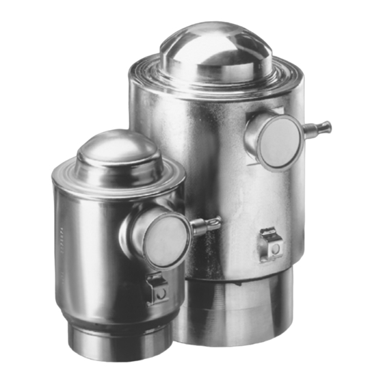
4 Specifications Compression Load Cell PR 6201 4.1.2 Load cells PR 6201/15, /25, /35 and DB (maximum capacities 100 t, 200 t, 300 t) Description Load cell Supporting ring Ring for lower load disc Lower load disc Flexible copper strap Positions not shown: Load cell grease incl. -
Page 14: Load Cells Pr 6201/520T And Db (Maximum Capacity 520 T)
Load cells PR 6201/520t and DB (maximum capacity 520 t) Description Load cell Positions not shown: Load cell grease incl. usage instructions Installation manual 9499 053 34202 Certificate Note: The load disc set PR 6143/55 has to be ordered separately, see Chapter 11.2.1. Sartorius Intec EN-12... -
Page 15: General Information
Green (LA version) Dual bridge The Dual Bridge load cell has two separate measuring circuits, which are independent of each other. The measuring circuits are adjusted in two separate adjustment chambers, for cable connections see Chapter 6.3. EN-13 Sartorius Intec... -
Page 16: Certificates For The Load Cell
Ta= -30°C to 70°C; T5 Ta= -30°C to 55°C - 4012 101 5688; NIFW DIP / II,III / 2 / EFG / T4A Ta= -30°C to 70°C; T5 Ta= -30°C to 55°C - 4012 101 5688; NIFW Sartorius Intec EN-14... -
Page 17: Dimensions
4.5.1 Load cells PR 6201/52… … 54 (maximum capacities 500 kg… … 50 t) all dimensions in mm Description Lower load disc Supporting ring Model R [mm] W [mm] ⌀a [mm] PR 6201/52…23 PR 6201/33…14 PR 6201/24…54 EN-15 Sartorius Intec... -
Page 18: Load Cell Pr 6201/15 (Maximum Capacity 100 T)
Compression Load Cell PR 6201 4 Specifications 4.5.2 Load cell PR 6201/15 (maximum capacity 100 t) all dimensions in mm Legend Description Lower load disc Supporting ring Ring for lower load disc Sartorius Intec EN-16... -
Page 19: Load Cell Pr 6201/25 (Max. Capacity 200 T), Pr 6201/35 (Max. Capacity 300 T)
4 Specifications Compression Load Cell PR 6201 4.5.3 Load cell PR 6201/25 (max. capacity 200 t), PR 6201/35 (max. capacity 300 t) all dimensions in mm Legend Description Lower load disc Supporting ring Ring for lower load disc EN-17 Sartorius Intec... -
Page 20: Load Cell Pr 6201/520T (Maximum Capacity 520 T)
Legend Description Upper/lower load disc Ring for upper load disc Supporting ring Ring for lower load disc Note: The scope of delivery does not include these parts! Load disc set PR 6143/55, see Chapter 11.2.1. Sartorius Intec EN-18... -
Page 21: Load Cell Pr 6201/15 Db (Maximum Capacity 100 T)
4 Specifications Compression Load Cell PR 6201 4.5.5 Load cell PR 6201/15 DB (maximum capacity 100 t) all dimensions in mm Legend Description Lower load disc Supporting ring Ring for lower load disc EN-19 Sartorius Intec... -
Page 22: Load Cell Pr 6201/25 Db (Max. Capacity 200 T), Pr 6201/35 Db (Max. Capacity 300 T)
Compression Load Cell PR 6201 4 Specifications 4.5.6 Load cell PR 6201/25 DB (max. capacity 200 t), PR 6201/35 DB (max. capacity 300 t) all dimensions in mm Legend Description Lower load disc Supporting ring Ring for lower load disc Sartorius Intec EN-20... -
Page 23: Load Cell Pr 6201/520T Db (Maximum Capacity 520 T)
Legend Description Upper/lower load disc Ring for upper load disc Supporting ring Ring for lower load disc Note: The scope of delivery does not include these parts! Load disc set PR 6143/55, see Chapter 11.2.1. EN-21 Sartorius Intec... -
Page 24: Ordering Information
Internal According to OIML R60 According to OIML R60 Ex version according to OIML R60 Ex version according to OIML R60 x = scale interval code Note: Error class of the individual types, see Chapter 4.7. Sartorius Intec EN-22... -
Page 25: Dual Bridge Load Cells (Maximum Capacities 100…300 T, 520 T)
4 Specifications Compression Load Cell PR 6201 4.6.2 Load cell PR 6201/15… … 35, 520t (maximum capacities 100… … 300 t, 520 t) Model Max. capacity Type Packaging Weight Gross/net PR 6201/15 100 t ..L/LA/N/NE 250×250×270 mm 12.0 kg/10.8 kg... -
Page 26: Technical Data
(LA = 4…20 mA) for E = 50 t 16 mA 2 … mV/V Tolerance permissible deviati- <1.0 <1.0 <0.25 <0.07 <0.07 <0.07 <0.07 % C on rated on from rated out- output put C Sartorius Intec EN-24... - Page 27 >5000 … >5000 MΩ impedance circuit and housing at 100V DC Insulation between circuit and … voltage housing (Ex versions only) Recom- to hold the specified 4…24 20…28 4…24 4…24 4…24 4…24 4…24 mended performance supply vol- tage EN-25 Sartorius Intec...
- Page 28 = 50 t <0.8 <0.8 <0.8 <0.8 <0.8 <0.8 … Definitions acc. to VDI/VDE 2637 The technical data given are intended solely as a product description and should not be interpreted as guaranteed properties in the legal sense. Sartorius Intec EN-26...
- Page 29 4 Specifications Compression Load Cell PR 6201 4.7.2 Load cell PR 6201/15… … 35, 520t (maximum capacities 100… … 300 t, 520 t) Description Description Abbr. L L, LE N, NE Unit 520t Accuracy class 0.06 Minimum dead load lowest limit of specified mea-...
- Page 30 … for E = 300 t … … … Definitions acc. to VDI/VDE 2637 The technical data given are intended solely as a product description and should not be interpreted as guaranteed properties in the legal sense. Sartorius Intec EN-28...
- Page 31 S per 10 K over <0.2 <0.06 /10 K Smin on Smin referred to C Temperature effect max. change of C per 10 K over B <0.1 <0.03 /10 K on C referred to C EN-29 Sartorius Intec...
- Page 32 = 300 t … for E = 520 t … Definitions acc. to VDI/VDE 2637 The technical data given are intended solely as a product description and should not be interpreted as guaranteed properties in the legal sense. Sartorius Intec EN-30...
-
Page 33: Installation
NOTICE Force shunts can cause measurement errors. All incoming and outgoing lines (hoses, pipes, cables) must be coupled to the measured object as flexibly as possible. EN-31 Sartorius Intec... -
Page 34: Installation Of The Upper Load Disc For Max. Capacity Of 500 Kg…50 T
Large load cell radius (35 mm) = 500 kg…10 t = 20…50 t Note: Load discs made of stainless steel are marked with a double groove. Further installation instructions can be found in the manuals of the respective mounting kits. Sartorius Intec EN-32... -
Page 35: Connection
= + supply + supply voltage gn = + meas./LC out + measuring voltage/+ load cell output bu = - supply – supply voltage gy = - meas./LC out – measuring voltage/– load cell output screen Screen EN-33 Sartorius Intec... -
Page 36: Connecting Single Load Cells Type La
+ sensor output = 2…10 mA bu = – supply voltage 0 V – sensor output screen Screen Note: The distance between load cell and electronic instrument must not exceed 500 m. 6.2.1 Connecting single load cells type LA Sartorius Intec EN-34... -
Page 37: Connecting Two Load Cells Type La
However, despite the robust nature of the materials used, the cable should be protected from excessive chemical and mechanical stresses. Preventing water from penetrating the end of the cable is also important "life insurance" for the system. EN-35 Sartorius Intec... -
Page 38: Cable Connections
Compression Load Cell PR 6201 6 Connection Cable connections Note: All components are only shown schematically. Color code black blue green gray white yellow Note: Not for type LA load cells. Sartorius Intec EN-36... - Page 39 6 Connection Compression Load Cell PR 6201 Load cells with one measuring circuit EN-37 Sartorius Intec...
- Page 40 Compression Load Cell PR 6201 6 Connection Load cells with two separate measuring circuits Sartorius Intec EN-38...
-
Page 41: Preparing For Calibration
A warm-up time of at least 30 minutes for the load cell is required before calibration of the weighing system. Smart calibration When using Sartorius Intec devices, we recommend always running "Smart Calibration” first. This allows all required values to be extracted from the Calibration Certificate supplied. -
Page 42: Mechanical Height Adaptation
5. Put thin, deburred sheets of metal (0.5…2 mm thick) between the upper mounting plate and the scale construction. 6. Measure the output voltages of the load cells again and correct the height of this load cell or another one. Sartorius Intec EN-40... -
Page 43: Troubleshooting
Check whether the output voltage without load is within the limits. Type Output voltage 0 mV ±0.02 mV/V D1/N/C3 0 mV ±0.01 mV/V for PR 6201/54.. 0 mV ±0.02 mV/V 3.2… 4 mA GAIN connected to +supply voltage 24 ±4 V, see Chap- ter 6.2.1. EN-41 Sartorius Intec... -
Page 44: Checking The Strain Gauge Bridge Of The Load Cell
Insulate the load cell cores. Max. test voltage Standard version 100 V DC Intrinsically safe version (PR …/..E) 500 V AC Insulation impedance Core – housing >5000 MΩ Core – screen >5000 MΩ Screen – housing <0,2 Ω Sartorius Intec EN-42... -
Page 45: Checking The Insulation Impedance Of The Connecting Cable
Checking the insulation impedance of the connecting cable Disconnect connecting cable from measuring instrument and load cells. Insulate the cores of the connecting cable. Insulation impedance Core – core ≥600 MΩ × km Core – screen ≥600 MΩ × km EN-43 Sartorius Intec... -
Page 46: Maintenance/Repairs/Cleaning
NOTICE Some cleaning agents may not be compatible with the load cell material. When using cleaning agents, ensure that their compatibility with the load cell material has been tested and approved (see Chapter 4.2). Sartorius Intec EN-44... -
Page 47: Disposal
Compression Load Cell PR 6201 10 Disposal If you no longer need the packaging after successful installation of the equipment, you should return it for recycling. The packaging is made from environmentally friendly materials, which are suitable for recycling. EN-45 Sartorius Intec... -
Page 48: Spare Parts And Accessories
9405 361 45002 500 kg…10 t porting ring PR 6143/54S @ 20…50 t Mounting kit PR 6145/08N 100 t 9405 361 45081 Mounting kit PR 6145/10S 200 t, 300 t 9405 361 45101 Pivot PR 6101/53N 9405 561 01531 Sartorius Intec EN-46... - Page 49 9405 361 43251 ≤200 kN SeismicMount PR 6144/54N 9405 361 44541 ≤370 kN SeismicMount PR 6144/15N 9405 361 44151 ≤440 kN SeismicMount PR 6144/35N 9405 361 44351 ≤520 kN SeismicMount PR 6144/55N 9405 361 44551 ≤520 kN EN-47 Sartorius Intec...
-
Page 50: Load Discs
PR 6130/08 (polycarbonate, 1…8 LC, IP65; not for PR 6201/..LA, ..LE, ..LDBE, ..NE, ..NDBE, ..D1E, ..CxE) 9405 361 30343 PR 6130/34Sa (1.4301, 1…4 LC, IP68, IP69, for use in legal metrology; not for PR 6201/..LA, ..LE, ..LDBE, ..NE, ..NDBE, ..D1E, ..CxE) Sartorius Intec EN-48... - Page 51 PR 6130/65S (1.4301, 1…4 LC, IP68, IP69, for use in legal metrology, ATEX, IECEx, FM; not for PR 6201/..LA) 9405 361 30683 PR 6130/68S (1.4404, 1…8 LC, IP68, IP69, for use in legal metrology, ATEX, IECEx, FM; not for PR 6201/..LA) EN-49 Sartorius Intec...
- Page 52 Sartorius Mechatronics T&H GmbH Meiendorfer Strasse 205 22145 Hamburg, Germany Phone: +49.40.67960.303 Fax: +49.40.67960.383 www.sartorius-intec.com © Sartorius Mechatronics T&H GmbH All rights are strictly reserved Printed in Germany...
- Page 53 Installationshandbuch Drucklast-Wägezelle PR 6201 Originalinstallationshandbuch 9499 053 34202 Ausgabe 1.0.1 06.06.2016 Sartorius Mechatronics T&H GmbH, Meiendorfer Str. 205, 22145 Hamburg, Deutschland Tel.: +49.40.67960.303 Fax: +49.40.67960.383...
- Page 54 Alle Angaben in diesem Dokument sind - soweit nicht gesetzlich vorgegeben - unverbindlich für Sartorius Intec und stehen unter Änderungsvorbehalt. Die Bedienung des Produktes darf nur von geschultem, fach- und sachkundigem Personal durchgeführt werden. Bei Schriftwechsel über dieses Produkt bitte Typ, Bezeichnung und Versionsnummer sowie alle mit dem Produkt in Zusammenhang stehenden Lizenznummern angeben.
- Page 55 4.1.1 Wägezellen PR 6201/52…54 (Nennlasten 500 kg…50 t) ................10 4.1.2 Wägezellen PR 6201/15, /25, /35 und DB (Nennlasten 100 t, 200 t, 300 t)........11 4.1.3 Wägezellen PR 6201/520t und DB (Nennlast 520 t) .................. 12 Allgemeine Informationen............................. 13 Dual Bridge ..................................
- Page 56 Drucklast-Wägezelle PR 6201 Inhaltsverzeichnis 4.7.1 Wägezellen PR 6201/52…54 (Nennlasten 500 kg…50 t) ................24 4.7.2 Wägezelle PR 6201/15…35, 520t (Nennlasten 100…300 t, 520 t) ............27 4.7.3 Dualbridge-Wägezelle (Nennlasten 100…300 t, 520 t)................29 Installation ..............................31 Sicherheitshinweise................................31 Einbau des oberen Druckstückes bei Nennlasten von 500 kg…50 t..............32 Anschluss ..............................33...
-
Page 57: Einleitung
Verletzungen führt, wenn die entsprechenden Vorsichtsmaßnahmen nicht getroffen werden. Entsprechende Vorsichtsmaßnahmen ergreifen. WARNUNG Warnung vor einer Gefahrenstelle und/oder vor Personenschäden WARNUNG vor möglicher eintretender Situation mit Tod und/oder schweren, irreversiblen Verletzungen als Folge, wenn die entsprechenden Vorsichtsmaßnahmen nicht getroffen werden. Entsprechende Vorsichtsmaßnahmen ergreifen. DE-3 Sartorius Intec... -
Page 58: Hotline
Warnung vor Sach- und/oder Umweltschäden. ACHTUNG vor möglicher eintretender Situation mit Sach- und/oder Umweltschäden als Folge, wenn die entsprechenden Vorsichtsmaßnahmen nicht getroffen werden. Entsprechende Vorsichtsmaßnahmen ergreifen. Hinweis: Anwendungstipps, nützliche Informationen und Hinweise. Hotline Telefon: +49.40.67960.444 Fax: +49.40.67960.474 eMail: technical.support.hh@sartorius-intec.com Sartorius Intec DE-4... -
Page 59: Sicherheitshinweise
Wareneingangskontrolle Die Sendung ist auf Vollständigkeit zu überprüfen. Mit einer Sichtprüfung ist festzustellen, ob die Sendung beschädigt wurde. Liegt eine Beanstandung vor, so muss beim Überbringer sofort reklamiert werden. Eine Sartorius Intec Verkaufs- oder Servicestelle muss benachrichtigt werden. Vor Inbetriebsetzung ACHTUNG Sichtprüfung! -
Page 60: Aufbauempfehlungen
Drucklast-Wägezelle PR 6201 3 Aufbauempfehlungen 3 Aufbauempfehlungen Anordnung der Wägezellen und Fesselungen Legende Diesen Punkt nicht fesseln. Lenker Lasteinleitung mögliche Bewegungsrichtung Sartorius Intec DE-6... -
Page 61: Anordnung Von Wägezellen Und Festlagern
Verfälschungen des Messergebnisses führen können. Daher ist besonderer Wert auf die Gestaltung, Anordnung und den Zustand der Fesselungselemente zu legen. Anordnung von Wägezellen und Festlagern Legende Festlager PR 6101 Diesen Punkt nicht fesseln. Lenker Lasteinleitung mögliche Bewegungsrichtung DE-7 Sartorius Intec... -
Page 62: Zusätzliche Abhebesicherung
Die Gewindestange (1) so montieren, dass diese ausreichend Bewegungsfreiheit in der Bohrung hat. Muttern (2) so kontern, dass der Abstand A* zur Unterlegscheibe (3) verbleibt. * A = 2 mm Dieser Abstand ist unbedingt einzuhalten, um Kraftnebenschlüsse zu vermeiden. Sartorius Intec DE-8... -
Page 63: Wahl Der Nennlast
Wenn die Gebrauchslast (E ) der Wägezelle z. B. durch fallende Lasten überschritten werden kann, dann ist eine mechanische Begrenzung in Lastrichtung vorzusehen. Bei Überschreiten der Bruchlast (E ) der Wägezelle besteht die Gefahr der mechanischen Zerstörung. DE-9 Sartorius Intec... -
Page 64: Spezifikation
4 Spezifikation 4 Spezifikation Lieferumfang der Wägezelle 4.1.1 Wägezellen PR 6201/52… … 54 (Nennlasten 500 kg… … 50 t) Pos. Bezeichnung Wägezelle Stützring unteres Druckstück Flexible Kupferleitung Positionen ohne Abbildung: Wägezellenfett inkl. Verwendungshinweise Installationshandbuch 9499 053 34202 Zertifikat Sartorius Intec DE-10... -
Page 65: Wägezellen Pr 6201/15, /25, /35 Und Db (Nennlasten 100 T, 200 T, 300 T)
4 Spezifikation Drucklast-Wägezelle PR 6201 4.1.2 Wägezellen PR 6201/15, /25, /35 und DB (Nennlasten 100 t, 200 t, 300 t) Pos. Bezeichnung Wägezelle Stützring Ring für unteres Druckstück unteres Druckstück Flexible Kupferleitung Positionen ohne Abbildung: Wägezellenfett inkl. Verwendungshinweise Installationshandbuch 9499 053 34202... -
Page 66: Wägezellen Pr 6201/520T Und Db (Nennlast 520 T)
4 Spezifikation 4.1.3 Wägezellen PR 6201/520t und DB (Nennlast 520 t) Pos. Bezeichnung Wägezelle Positionen ohne Abbildung: Wägezellenfett inkl. Verwendungshinweise Installationshandbuch 9499 053 34202 Zertifikat Hinweis: Der Druckstücksatz PR 6143/55 muss separat bestellt werden, siehe Kapitel 11.2.1. Sartorius Intec DE-12... -
Page 67: Allgemeine Informationen
≥75 mm bei flexibler Verlegung Material Kabelmantel thermoplastisches Elastomer (TPE) Farbe Kabelmantel grau (Standardausführung) blau (Ex-Ausführung) grün (LA-Ausführung) Dual Bridge Die Dual Bridge-Wägezelle hat zwei getrennt voneinander unabhängige Messkreise. Die Messkreise werden in zwei getrennten Abgleichkammern abgeglichen, Kabelverbindungen siehe Kapitel 6.3. DE-13 Sartorius Intec... -
Page 68: Zertifikate Der Wägezelle
Ta= -30°C to 70°C; T5 Ta= -30°C to 55°C - 4012 101 5688; NIFW DIP / II,III / 2 / EFG / T4A Ta= -30°C to 70°C; T5 Ta= -30°C to 55°C - 4012 101 5688; NIFW Sartorius Intec DE-14... -
Page 69: Abmessungen
Drucklast-Wägezelle PR 6201 Abmessungen 4.5.1 Wägezellen PR 6201/52… … 54 (Nennlasten 500 kg… … 50 t) alle Abmessungen in mm Pos. Bezeichnung Unteres Druckstück Stützring Modell R [mm] B [mm] ⌀a [mm] PR 6201/52…23 PR 6201/33…14 PR 6201/24…54 DE-15 Sartorius Intec... -
Page 70: Wägezelle Pr 6201/15 (Nennlast 100 T)
Drucklast-Wägezelle PR 6201 4 Spezifikation 4.5.2 Wägezelle PR 6201/15 (Nennlast 100 t) alle Abmessungen in mm Legende Pos. Bezeichnung unteres Druckstück Stützring Ring für unteres Druckstück Sartorius Intec DE-16... -
Page 71: Wägezelle Pr 6201/25 (Nennlast 200 T), Pr 6201/35 (Nennlast 300 T)
4 Spezifikation Drucklast-Wägezelle PR 6201 4.5.3 Wägezelle PR 6201/25 (Nennlast 200 t), PR 6201/35 (Nennlast 300 t) alle Abmessungen in mm Legende Pos. Bezeichnung unteres Druckstück Stützring Ring für unteres Druckstück DE-17 Sartorius Intec... -
Page 72: Wägezelle Pr 6201/520T (Nennlast 520 T)
Wägezelle PR 6201/520t (Nennlast 520 t) alle Abmessungen in mm Legende Pos. Bezeichnung oberes/unteres Druckstück Ring für oberes Druckstück Stützring Ring für unteres Druckstück Hinweis: Diese Teile sind nicht im Lieferumfang enthalten! Druckstücksatz PR 6143/55 siehe Kapitel 11.2.1. Sartorius Intec DE-18... -
Page 73: Wägezelle Pr 6201/15 Db (Nennlast 100 T)
4 Spezifikation Drucklast-Wägezelle PR 6201 4.5.5 Wägezelle PR 6201/15 DB (Nennlast 100 t) alle Abmessungen in mm Legende Pos. Bezeichnung unteres Druckstück Stützring Ring für unteres Druckstück DE-19 Sartorius Intec... -
Page 74: Wägezelle Pr 6201/25 Db (Nennlast 200 T), Pr 6201/35 Db (Nennlast 300 T)
Drucklast-Wägezelle PR 6201 4 Spezifikation 4.5.6 Wägezelle PR 6201/25 DB (Nennlast 200 t), PR 6201/35 DB (Nennlast 300 t) alle Abmessungen in mm Legende Pos. Bezeichnung unteres Druckstück Stützring Ring für unteres Druckstück Sartorius Intec DE-20... -
Page 75: Wägezelle Pr 6201/520T Db (Nennlast 520 T)
Wägezelle PR 6201/520t DB (Nennlast 520 t) alle Abmessungen in mm Legende Pos. Bezeichnung oberes/unteres Druckstück Ring für oberes Druckstück Stützring Ring für unteres Druckstück Hinweis: Diese Teile sind nicht im Lieferumfang enthalten! Druckstücksatz PR 6143/55 siehe Kapitel 11.2.1. DE-21 Sartorius Intec... -
Page 76: Bestellinformationen
250×250×180 mm 5,1 kg/4,2 kg C3E/C4/C4E/C5/C5E Legende Genauigkeitsklasse intern intern mit Verstärker intern nach OIML R60 nach OIML R60 Ex-Version nach OIML R60 Ex-Version nach OIML R60 x = Teilezahl Hinweis: Fehlerklasse der einzelnen Typen siehe Kapitel 4.7. Sartorius Intec DE-22... -
Page 77: Dualbridge-Wägezellen (Nennlasten 100…300 T, 520 T)
4 Spezifikation Drucklast-Wägezelle PR 6201 4.6.2 Wägezelle PR 6201/15… … 35, 520t (Nennlasten 100… … 300 t, 520 t) Modell Nennlast Verpackung Gewicht Brutto/Netto PR 6201/15 100 t ..L/LA/N/NE 250×250×270 mm 12,0 kg/10,8 kg PR 6201/25 200 t ..L/N/NE 280×280×320 mm... -
Page 78: Technische Daten
Nennlast (LA = 4…20 mA) für E = 50 t 16 mA 2 … mV/V Relative zulässige Abwei- <1,0 <1,0 <0,25 <0,07 <0,07 <0,07 <0,07 % C Kennwert- chung vom Nenn- abwei- kennwert C chung Sartorius Intec DE-24... - Page 79 E = 50 t … … … … … … Ω ±0,5 Isolations- zwischen Innen- >5000 … >5000 MΩ widerstand schaltung und Ge- häuse, 100 V DC Isolations- zwischen Schaltung … festigkeit und Gehäuse (nur für Ex-Versionen) DE-25 Sartorius Intec...
- Page 80 E = 30 t für E = 50 t <0,8 <0,8 <0,8 <0,8 <0,8 <0,8 … Definitionen nach VDI/VDE 2637 Die angegebenen technischen Daten dienen allein zur Produktbeschreibung und sind nicht als zugesicherte Eigenschaften im Rechtssinne aufzufassen. Sartorius Intec DE-26...
- Page 81 4 Spezifikation Drucklast-Wägezelle PR 6201 4.7.2 Wägezelle PR 6201/15… … 35, 520t (Nennlasten 100… … 300 t, 520 t) Bezeichnung Beschreibung Abk. L, LE N, NE Einheit 520t Fehlerklasse 0,06 Mindestvorlast (Tot- untere Grenze des spezifizier- last) ten Messbereiches Nennlast...
- Page 82 … für E = 200 t … … für E = 300 t … … … Definitionen nach VDI/VDE 2637 Die angegebenen technischen Daten dienen allein zur Produktbeschreibung und sind nicht als zugesicherte Eigenschaften im Rechtssinne aufzufassen. Sartorius Intec DE-28...
-
Page 83: Dualbridge-Wägezelle (Nennlasten 100…300 T, 520 T)
Änderung <0,2 <0,06 /10 K Smin des Mindestvorlast- von S pro 10 K im B signals Temp.-Koeffizient max. auf C bezogene Änderung <0,1 <0,03 /10 K des Kennwertes C von C pro 10 K im B DE-29 Sartorius Intec... - Page 84 = 200 t … für E = 300 t … für E = 520 t … Definitionen nach VDI/VDE 2637 Die angegebenen technischen Daten dienen allein zur Produktbeschreibung und sind nicht als zugesicherte Eigenschaften im Rechtssinne aufzufassen. Sartorius Intec DE-30...
-
Page 85: Installation
Wägezellen unbedingt gegen direkte Wärme- bzw. Kälteeinwirkung (Sonne, Wind, Wärmestrahlung) schützen, z. B. durch Schutzbleche oder Schutzgehäuse. ACHTUNG Kraftnebenschlüsse können zu Messfehlern führen. Alle Zu- und Ableitungen (Schläuche, Rohre, Kabel) so flexibel wie möglich an das Messobjekt koppeln. DE-31 Sartorius Intec... -
Page 86: Einbau Des Oberen Druckstückes Bei Nennlasten Von 500 Kg…50 T
In den nachfolgenden Abbildungen sind Wägezelle und oberes Druckstück schematisch dargestellt. kleiner Wägezellen-Radius (15 mm) großer Wägezellen-Radius (35 mm) = 500 kg…10 t = 20…50 t Hinweis: Druckstücke aus rostfreiem Edelstahl sind mit einer Doppelrille markiert. Weitere Installationshinweise den Handbüchern der entsprechenden Einbausätze entnehmen. Sartorius Intec DE-32... -
Page 87: Anschluss
Typ L, D1/N, D1E/NE, Cx, CxE rd = + supply + Speisespannung gn = + meas./LC out + Messspannung /+ Wägezellenausgang bu = - supply – Speisespannung gy = - meas./LC out – Messspannung /– Wägezellenausgang screen Schirm DE-33 Sartorius Intec... -
Page 88: Anschluss Von Einer Wägezelle Typ La
Betrieb mit 2 Sensoren + Sensorausgang = 2…10 mA bu = – Speisespannung 0 V – Sensorausgang screen Schirm Hinweis: Die Kabellänge zwischen Wägezelle und Elektronik darf max. 500 m betragen. 6.2.1 Anschluss von einer Wägezelle Typ LA Sartorius Intec DE-34... -
Page 89: Anschluss Von Zwei Wägezellen Typ La
Faden gewährleisten eine extrem lange Lebensdauer auch unter schwierigen Einsatzbedingungen. Trotz größter Robustheit der eingesetzten Materialien ist das Kabel gegen übermäßige chemische und mechanische Beanspruchung zu sichern. Insbesondere ist der Schutz gegen das Eindringen von Wasser am Ende des Kabels eine wichtige "Lebensversicherung". DE-35 Sartorius Intec... -
Page 90: Kabelverbindungen
Drucklast-Wägezelle PR 6201 6 Anschluss Kabelverbindungen Hinweis: Alle Bauteile sind nur schematisch dargestellt. Farbcode schwarz blau grün grau weiß gelb Hinweis: Nicht für Wägezellen Typ LA. Sartorius Intec DE-36... - Page 91 6 Anschluss Drucklast-Wägezelle PR 6201 Wägezellen mit einem Messkreis DE-37 Sartorius Intec...
- Page 92 Drucklast-Wägezelle PR 6201 6 Anschluss Wägezellen mit zwei getrennten Messkreisen Sartorius Intec DE-38...
-
Page 93: Vorbereitung Zur Justierung
Die Wägezelle benötigt eine Aufwärmzeit von mindestens 30 Minuten vor Beginn der Justierung der Wägeeinrichtung. Smart Calibration Wir empfehlen beim Einsatz von Sartorius Intec Geräten immer zunächst die "SmartCalibration" zu benutzen. Dabei werden alle notwendigen Werte dem mitgelieferten Kalibrierzertifikat (Calibration Certificate) entnommen. -
Page 94: Mechanischer Höhenausgleich
4. Wägeobjekt unmittelbar neben der betroffenen Wägezelle anheben. 5. Dünne, entgratete Ausgleichsbleche (0,5…2 mm Dicke) zwischen obere Einbauplatte und Waagenkonstruktion legen. 6. Die Ausgangsspannungen der Wägezellen erneut messen und ggf. Höhe dieser bzw. einer weiteren Wägezelle korrigieren. Sartorius Intec DE-40... -
Page 95: Fehlersuche
Prüfen, ob die Ausgangsspannung ohne Last nicht überschritten wird. Ausgangsspannung 0 mV ±0,02 mV/V D1/N/C3 0 mV ±0,01 mV/V bei PR 6201/54.. 0 mV ±0,02 mV/V 3,2… 4 mA GAIN mit +Speisespannung 24 ±4 V verbinden, siehe Kapi- tel 6.2.1. DE-41 Sartorius Intec... -
Page 96: Dms Brückenschaltung Der Wägezelle Überprüfen
Prüfspannung nie zwischen zwei Adern des Wägezellenkabels legen. Adern der Wägezellen isolieren. Max. Prüfspannung Standardausführung 100 V DC Eigensichere Ausführung (PR …/..E) 500 V AC Isolationswiderstand Ader – Gehäuse >5000 MΩ Ader – Schirm >5000 MΩ Schirm – Gehäuse <0,2 Ω Sartorius Intec DE-42... -
Page 97: Isolationswiderstand Des Verbindungskabels Überprüfen
8 Fehlersuche Drucklast-Wägezelle PR 6201 8.3.4 Isolationswiderstand des Verbindungskabels überprüfen Verbindungskabel von Messinstrument und Wägezellen lösen. Adern des Verbindungskabels isolieren. Isolationswiderstand Ader – Ader ≥600 MΩ × km Ader – Schirm ≥600 MΩ × km DE-43 Sartorius Intec... -
Page 98: Wartung/Reparatur/Reinigung
ACHTUNG Eine Unverträglichkeit der Reinigungsmittel mit den Materialien der Wägezelle ist möglich. Beim Einsatz von Reinigungsmitteln ist zu beachten, dass ausschließlich Reinigungsmittel verwendet werden dürfen, deren Verträglichkeit mit den Materialien der Wägezelle (siehe Kapitel 4.2) geprüft wurden. Sartorius Intec DE-44... -
Page 99: Entsorgung
10 Entsorgung Drucklast-Wägezelle PR 6201 10 Entsorgung Wird die Verpackung nicht mehr benötigt, diese der örtlichen Müllentsorgung zuführen. Die Verpackung besteht durchweg aus umweltverträglichen Materialien, die als wertvolle Sekundärrohstoffe dienen. DE-45 Sartorius Intec... -
Page 100: Ersatzteile Und Zubehör
Einbausatz PR 6145/00S inkl. unteres Druckstück mit 9405 361 45002 500 kg…10 t Stützring PR 6143/54S @ 20…50 t Einbausatz PR 6145/08N 100 t 9405 361 45081 Einbausatz PR 6145/10S 200 t, 300 t 9405 361 45101 Festlager PR 6101/53N 9405 561 01531 Sartorius Intec DE-46... - Page 101 9405 361 43251 ≤200 kN SeismicMount PR 6144/54N 9405 361 44541 ≤370 kN SeismicMount PR 6144/15N 9405 361 44151 ≤440 kN SeismicMount PR 6144/35N 9405 361 44351 ≤520 kN SeismicMount PR 6144/55N 9405 361 44551 ≤520 kN DE-47 Sartorius Intec...
-
Page 102: Druckstücke
PR 6130/08 (Polycarbonat, 1…8 WZ, IP65; nicht für PR 6201/..LA, ..LE, ..LD- BE, ..NE, ..NDBE, ..D1E, ..CxE) 9405 361 30343 PR 6130/34Sa (1.4301, 1…4 WZ, IP68, IP69, eichfähig; nicht für PR 6201/..LA, ..LE, ..LDBE, ..NE, ..NDBE, ..D1E, ..CxE) Sartorius Intec DE-48... - Page 103 PR 6201/..LA) 9405 361 30653 PR 6130/65S (1.4301, 1…4 WZ, IP68, IP69, eichfähig, ATEX, IECEx, FM; nicht für PR 6201/..LA) 9405 361 30683 PR 6130/68S (1.4404, 1…8 WZ, IP68, IP69, eichfähig, ATEX, IECEx, FM; nicht für PR 6201/..LA) DE-49 Sartorius Intec...
- Page 104 Sartorius Mechatronics T&H GmbH Meiendorfer Straße 205 22145 Hamburg, Germany Tel: +49.40.67960.303 Fax: +49.40.67960.383 www.sartorius-intec.com © Sartorius Mechatronics T&H GmbH All rights are strictly reserved Printed in Germany...
-
Page 105: Capteur De Compression Pr 6201
Manuel d’installation Capteur de compression PR 6201 Traduction du manuel d'installation original 9499 053 34202 Édition 1.0.1 06/06/2016 Sartorius Mechatronics T&H GmbH, Meiendorfer Str. 205, 22145 Hambourg, Allemagne Tél : +49.40.67960.303 Fax : +49.40.67960.383... - Page 106 Toutes les informations contenues dans ce document sont sujettes à modification sans préavis et ne constituent en aucun cas un engagement de la part de Sartorius Intec , sauf prescription légale contraire. Seuls les membres du personnel qualifiés ayant reçu la formation correspondante sont autorisés à utiliser ce produit.
- Page 107 Capteurs de pesage PR 6201/52…54 (capacité maximale 500 kg…50 t)..........10 4.1.2 Capteurs de pesage PR 6201/15, /25, /35 et DB (capacités max. 100 t, 200 t, 300 t)..... 11 4.1.3 Capteurs de pesage PR 6201/520t et DB (capacité maximale 520 t) ........... 12 Informations générales ..............................
- Page 108 4.7.1 Capteurs de pesage PR 6201/52…54 (capacité maximale 500 kg…50 t)..........24 4.7.2 Capteur de pesage PR 6201/15…35, 520 t (capacité maximale 100…300 t, 520 t)......27 4.7.3 Capteurs de pesage Dualbridge (capacités maximales 100…300 t, 520 t)........... 29 Installation ..............................32 Consignes de sécurité...
-
Page 109: Introduction
ATTENTION Avertissement contre un risque de blessures ATTENTION face à une situation susceptible de survenir et entraînant de légères blessures réversibles si les mesures de précaution correspondantes ne sont pas prises. Prendre les mesures de précaution correspondantes. FR-3 Sartorius Intec... -
Page 110: Hotline
Prendre les mesures de précaution correspondantes. Remarque: Conseils, informations et remarques utiles. Hotline Téléphone : +49.40.67960.444 Fax : +49.40.67960.474 E-mail : technical.support.hh@sartorius-intec.com Sartorius Intec FR-4... -
Page 111: Consignes De Sécurité
Vérifiez si la livraison est complète. Contrôlez visuellement qu'elle n'a pas été endommagée pendant le transport. Si nécessaire, déposez immédiatement une réclamation auprès du transporteur. Informez le service des ventes ou le centre de service après-vente Sartorius Intec . Avant la mise en service AVIS Contrôle visuel ! -
Page 112: Recommandation D'installation
Capteur de compression PR 6201 3 Recommandation d’installation 3 Recommandation d’installation Disposition des capteurs de pesage et des entraves Légende Ne pas entraver ce point. Dispositif de guidage Transmission de la charge Direction possible du mouvement Sartorius Intec FR-6... -
Page 113: Disposition Des Capteurs De Pesage Et Des Paliers Fixes
à l'état des éléments d'entrave. Disposition des capteurs de pesage et des paliers fixes Légende Palier fixe PR 6101 Ne pas entraver ce point. Dispositif de guidage Transmission de la charge Direction possible du mouvement FR-7 Sartorius Intec... -
Page 114: Dispositif De Protection Contre Le Basculement Supplémentaire
Monter la tige filetée (1) de manière à ce qu’elle soit suffisamment mobile dans l’orifice. Bloquer les écrous (2) de manière à laisser un écartement A* par rapport à la rondelle (3). * A = 2 mm Pour éviter des dérivations de force, il est indispensable de respecter cet écartement. Sartorius Intec FR-8... -
Page 115: Sélection De La Capacité Maximale
) du capteur de pesage peut être dépassée (par exemple par la chute d’une charge), il convient de prévoir une limitation mécanique dans le sens de la charge. Des forces dépassant la charge de rupture (E ) du capteur de pesage risquent de détruire le capteur. FR-9 Sartorius Intec... -
Page 116: Spécification
Capteurs de pesage PR 6201/52… … 54 (capacité maximale 500 kg… … 50 t) Pos. Désignation Capteur de pesage Bague d’appui Pièce de pression inférieure Fil de cuivre souple Positions non représentées : Graisse pour capteurs de pesage avec conseils d’utilisation Manuel d’installation 9499 053 34202 Certificat Sartorius Intec FR-10... -
Page 117: Capteurs De Pesage Pr 6201/15, /25, /35 Et Db (Capacités Max. 100 T, 200 T, 300 T)
4 Spécification Capteur de compression PR 6201 4.1.2 Capteurs de pesage PR 6201/15, /25, /35 et DB (capacités max. 100 t, 200 t, 300 t) Pos. Désignation Capteur de pesage Bague d’appui Anneau pour pièce de pression inférieure Pièce de pression inférieure Fil de cuivre souple Positions non représentées :... -
Page 118: Capteurs De Pesage Pr 6201/520T Et Db (Capacité Maximale 520 T)
Capteur de pesage Positions non représentées : Graisse pour capteurs de pesage avec conseils d’utilisation Manuel d’installation 9499 053 34202 Certificat Remarque: Le kit de pièces de pression PR 6143/55 doit être commandé séparément, voir chapitre 11.2.1. Sartorius Intec FR-12... -
Page 119: Informations Générales
(version Ex) vert (version LA) Dual Bridge Le capteur de pesage Dual Bridge possède deux circuits de mesure séparés indépendants. Les circuits de mesure sont étalonnés dans deux chambres d’étalonnage séparées (raccordement des câbles, voir chapitre 6.3). FR-13 Sartorius Intec... -
Page 120: Certificats Du Capteur De Pesage
- 4012 101 5688 ; NIFW DIP / II,III / 2 / EFG / T4A Ta= de -30 °C à 70 °C ; T5 Ta= de -30 °C à 55 °C - 4012 101 5688 ; NIFW Sartorius Intec FR-14... -
Page 121: Dimensions
Capteurs de pesage PR 6201/52… … 54 (capacité maximale 500 kg… … 50 t) Toutes les dimensions sont en mm. Pos. Désignation Pièce de pression inférieure Bague d’appui Modèle R [mm] L [mm] ⌀a [mm] PR 6201/52…23 PR 6201/33…14 PR 6201/24…54 FR-15 Sartorius Intec... -
Page 122: Capteur De Pesage Pr 6201/15 (Capacité Maximale 100 T)
Capteur de compression PR 6201 4 Spécification 4.5.2 Capteur de pesage PR 6201/15 (capacité maximale 100 t) Toutes les dimensions sont en mm. Légende Pos. Désignation Pièce de pression inférieure Bague d’appui Anneau pour pièce de pression inférieure Sartorius Intec... -
Page 123: Capteur De Pesage Pr 6201/25 (Capacité Max. 200 T), Pr 6201/35 (Capacité Max. 300 T)
4.5.3 Capteur de pesage PR 6201/25 (capacité max. 200 t), PR 6201/35 (capacité max. 300 t) Toutes les dimensions sont en mm. Légende Pos. Désignation Pièce de pression inférieure Bague d’appui Anneau pour pièce de pression inférieure FR-17 Sartorius Intec... -
Page 124: Capteur De Pesage Pr 6201/520T (Capacité Maximale 520 T)
Désignation Pièce de pression supérieure/inférieure Anneau pour pièce de pression supérieure Bague d’appui Anneau pour pièce de pression inférieure Remarque: Ces pièces ne sont pas fournies ! Kit de pièces de pression PR 6143/55, voir chapitre 11.2.1. Sartorius Intec FR-18... -
Page 125: Capteur De Pesage Pr 6201/15 Db (Capacité Maximale 100 T)
4 Spécification Capteur de compression PR 6201 4.5.5 Capteur de pesage PR 6201/15 DB (capacité maximale 100 t) Toutes les dimensions sont en mm. Légende Pos. Désignation Pièce de pression inférieure Bague d’appui Anneau pour pièce de pression inférieure FR-19... -
Page 126: Capteur De Pesage Pr 6201/25 Db (Capacité Max. 200 T), Pr 6201/35 Db
Capteur de pesage PR 6201/25 DB (capacité max. 200 t), PR 6201/35 DB (capacité max. 300 t) Toutes les dimensions sont en mm. Légende Pos. Désignation Pièce de pression inférieure Bague d’appui Anneau pour pièce de pression inférieure Sartorius Intec FR-20... -
Page 127: Capteur De Pesage Pr 6201/520T Db (Capacité Maximale 520 T)
Désignation Pièce de pression supérieure/inférieure Anneau pour pièce de pression supérieure Bague d’appui Anneau pour pièce de pression inférieure Remarque: Ces pièces ne sont pas fournies ! Kit de pièces de pression PR 6143/55, voir chapitre 11.2.1. FR-21 Sartorius Intec... -
Page 128: Informations De Commande
Classe de précision interne interne avec amplificateur interne après OIML R60 après OIML R60 Version Ex après OIML R60 Version Ex après OIML R60 x = valeur de l’échelon Remarque: Classe d’erreur de chaque type, voir chapitre 4.7. Sartorius Intec FR-22... -
Page 129: Capteurs De Pesage Dualbridge (Capacité Maximale 100…300 T, 520 T)
4 Spécification Capteur de compression PR 6201 4.6.2 Capteur de pesage PR 6201/15… … 35, 520 t (capacité maximale 100… … 300 t, 520 t) Modèle Capacité max. Type Emballage Poids Brut/Net PR 6201/15 100 t ..L/LA/N/NE 250×250×270 mm 12,0 kg/10,8 kg... -
Page 130: Caractéristiques Techniques
4…20 mA) pour E = 50 t 16 mA 2 … mV/V Écart relatif Écart admissible de <1,0 <1,0 <0,25 <0,07 <0,07 <0,07 <0,07 % C de la sensi- la sensibilité nomi- bilité nomi- nale C nale Sartorius Intec FR-24... - Page 131 610 ±0,5 Ω de sortie mesure ±3 ±1 pour E = 50 t … … … … … … Ω ±0,5 Résistance entre le circuit in- >5000 … >5000 MΩ d’isolement terne et le boîtier, 100 V CC FR-25 Sartorius Intec...
- Page 132 Influence de la pres- g/kPa Smin de la pres- sion atmosphérique sion ambi- sur le signal de ante précharge minimale jusqu’à E = 2 t g/kPa = 3…10 t Smin à partir de E g/kPa Smin 20 t Sartorius Intec FR-26...
- Page 133 Les caractéristiques techniques indiquées servent uniquement à décrire les produits et ne constituent pas une garantie des propriétés au sens juridique. 4.7.2 Capteur de pesage PR 6201/15… … 35, 520 t (capacité maximale 100… … 300 t, 520 t) Désignation Description L, LE N, NE Unité...
- Page 134 Plage de tempéra- Fonctionnement continu sans °C -40… -30… -40… -40… ture opérationnelle dommage Plage de tempéra- sans sollicitation mécanique et °C -40… -40… -40… -40… ture de stockage électrique Sartorius Intec FR-28...
-
Page 135: Capteurs De Pesage Dualbridge (Capacités Maximales 100…300 T, 520 T)
= 520 t … Charge de rupture Risque de dommages mécaniques … >500 pour E = 100 t pour E = 200 t … >500 pour E = 300 t … >333 pour E = 520 t … FR-29 Sartorius Intec... - Page 136 Plage nominale en observant les ca- 4…24 4…24 la tension ractéristiques techniques d'alimentation Tension Fonctionnement continu sans dom- d'alimentation max. mage Versions Ex : Plage nominale de Plage nominale en observant les ca- °C -10…+55 -10…+55 la température am- ractéristiques techniques biante Sartorius Intec FR-30...
- Page 137 E = 300 t … pour E = 520 t … Définitions selon VDI/VDE 2637 Les caractéristiques techniques indiquées servent uniquement à décrire les produits et ne constituent pas une garantie des propriétés au sens juridique. FR-31 Sartorius Intec...
-
Page 138: Installation
AVIS Des dérivations de force peuvent provoquer des erreurs de mesure. Toutes les lignes d'entrée et de sortie (tuyaux, tubes, câbles) doivent être raccordées de la façon la plus souple possible. Sartorius Intec FR-32... - Page 139 (35 mm) = 500 kg…10 t = 20…50 t Remarque: Les pièces de pression en acier inoxydable sont identifiées par une double rainure. Pour de plus amples informations concernant l’installation, reportez-vous aux manuels des kits de montage correspondants. FR-33 Sartorius Intec...
-
Page 140: Instructions De Raccordement
= + meas./LC out + tension de mesure/+ sortie du capteur de pesage bu = - supply – tension d’alimentation gy = - meas./LC out – tension de mesure/– sortie du capteur de pesage screen Blindage Sartorius Intec FR-34... -
Page 141: Raccordement D'un Capteur De Pesage De Type La
– tension d’alimentation 0 V – sortie du capteur screen Blindage Remarque: La longueur de câble maximale entre le capteur de pesage et l’électronique est de 500 m. 6.2.1 Raccordement d’un capteur de pesage de type LA FR-35 Sartorius Intec... -
Page 142: Raccordement De Deux Capteurs De Pesage De Type La
Kevlar, garantissent une durée de vie très longue, même dans des conditions difficiles. Malgré la robustesse des matériaux, protégez le câble contre les sollicitations chimiques et mécaniques excessives. La protection contre la pénétration d’eau à l’extrémité du câble est une véritable "assurance de longévité". Sartorius Intec FR-36... -
Page 143: Raccordements Des Câbles
Capteur de compression PR 6201 Raccordements des câbles Remarque: Tous les composants ne sont représentés que de manière schématique. Code couleur noir bleu vert gris rouge blanc jaune Remarque: Pas pour capteurs de pesage de type LA. FR-37 Sartorius Intec... - Page 144 Capteur de compression PR 6201 6 Instructions de raccordement Capteur de pesage avec un circuit de mesure Sartorius Intec FR-38...
- Page 145 6 Instructions de raccordement Capteur de compression PR 6201 Capteur de pesage avec deux circuits de mesure séparés indépendants FR-39 Sartorius Intec...
-
Page 146: Préparations Avant L'étalonnage
Avant l’ajustage du dispositif de pesage, le capteur de pesage a besoin d'un temps de préchauffage d'au moins 30 minutes. Smart Calibration Si vous utilisez des appareils Sartorius Intec , nous vous recommandons de toujours utiliser d'abord "SmartCalibration". Toutes les valeurs nécessaires se trouvent dans le certificat de calibrage (Calibration Certificate) fourni. -
Page 147: Réglage Mécanique De La Hauteur
6. Mesurer à nouveau les tensions de sortie des capteurs de pesage. Si nécessaire, corriger la hauteur du capteur de pesage concerné ou d’un autre capteur. FR-41 Sartorius Intec... -
Page 148: Localisation Des Défauts
Vérifier si la tension de sortie sans charge est à l'intérieur des limites. Type Tension de sortie 0 mV ±0,02 mV/V D1/N/C3 0 mV ±0,01 mV/V avec PR 6201/54.. 0 mV ±0,02 mV/V 3,2… 4 mA GAIN, connexe avec alimentation+ 24 ±4 V, voir paragra- phe 6.2.1. Sartorius Intec FR-42... -
Page 149: Vérification Du Circuit En Pont Des Jauges De Contrainte Du Capteur De Pesage
Isoler les fils des capteurs de pesage. Tension d'essai max. Version standard 100 V CC Version à sécurité intrinsèque (PR …/..E) 500 V CA Résistance d’isolement Fil – Boîtier >5000 MΩ Fil – Blindage >5000 MΩ Blindage – Boîtier <0,2 Ω FR-43 Sartorius Intec... -
Page 150: Vérification De La Résistance D'isolement Du Câble De Connexion
Déconnecter le câble de connexion de l'appareil de mesure et des capteurs de pesage. Isoler les fils du câble de connexion. Résistance d’isolement Fil – Fil ≥600 MΩ × km Fil – Blindage ≥600 MΩ × km Sartorius Intec FR-44... -
Page 151: Maintenance/Réparation/Nettoyage
Il est possible que les produits de nettoyage ne soient pas compatibles avec les matériaux du capteur de pesage. Veiller à n'utiliser que des produits de nettoyage dont la compatibilité avec les matériaux du capteur de pesage (voir chapitre 4.2) a été testée. FR-45 Sartorius Intec... -
Page 152: Recyclage
Capteur de compression PR 6201 10 Recyclage 10 Recyclage Si vous n’avez plus besoin de l’emballage de votre appareil, veuillez l’apporter au service local de retraitement des déchets. Cet emballage se compose entièrement de matériaux écologiques recyclables. Sartorius Intec FR-46... -
Page 153: Pièces De Rechange Et Accessoires
PR 6143/54S @ 20…50 t Kit de montage PR 6145/08N 100 t 9405 361 45081 Kit de montage PR 6145/10S 200 t, 300 t 9405 361 45101 Palier fixe PR 6101/53N 9405 561 01531 FR-47 Sartorius Intec... - Page 154 9405 361 43251 ≤200 kN SeismicMount PR 6144/54N 9405 361 44541 ≤370 kN SeismicMount PR 6144/15N 9405 361 44151 ≤440 kN SeismicMount PR 6144/35N 9405 361 44351 ≤520 kN SeismicMount PR 6144/55N 9405 361 44551 ≤520 kN Sartorius Intec FR-48...
-
Page 155: Pièces De Pression
PR 6130/04 (aluminium, 1…4 WZ, IP67 ; non approprié pour PR 6201/..LA, ..LE, ..LDBE, ..NE, ..NDBE, ..D1E, ..CxE) 9405 361 30083 PR 6130/08 (polycarbonate, 1…8 WZ, IP65 ; non approprié pour PR 6201/..LA, ..LE, ..LDBE, ..NE, ..NDBE, ..D1E, ..CxE) FR-49 Sartorius Intec... - Page 156 PR 6130/65S (1.4301, 1…4 WZ, IP68, IP69, pour usage ML, ATEX, IECEx, FM ; non approprié pour PR 6201/..LA) 9405 361 30683 PR 6130/68S (1.4404, 1…8 WZ, IP68, IP69, pour usage ML, ATEX, IECEx, FM ; non approprié pour PR 6201/..LA) Sartorius Intec FR-50...
- Page 157 Sartorius Mechatronics T&H GmbH Meiendorfer Strasse 205 22145 Hambourg, Allemagne Tél. : +49.40.67960.303 Fax : +49.40.67960.383 © Sartorius Mechatronics T&H GmbH Tous droits réservés. Imprimé en Allemagne. documento scaricato da www.geass.com...