Table des Matières
Publicité
Les langues disponibles
Les langues disponibles
Liens rapides
INSTALLER: LEAVE THIS MANUAL WITH THE APPLIANCE.
CONSUMER: RETAIN THIS MANUAL FOR FUTURE REFERENCE.
NEVER LEAVE CHILDREN OR OTHER AT RISK INDIVIDUALS ALONE WITH THE APPLIANCE
CONFORMS TO AMERICAN NATIONAL STANDARDS: ANSI Z21.50, CERTIFIED TO CANADIAN CSA 2.22 FOR VENTED GAS FIREPLACES.
CERTIFIED FOR CANADA AND UNITED STATES USING ANSI/CSA METHODS.
SAFETY INFORMATION
WARNING
!
If the information in these instructions
are not followed exactly, a fi re or
explosion may result causing property
damage, personal injury or loss of life.
- Do not store or use gasoline or other fl ammable
vapors and liquids in the vicinity of this or any
other appliance.
- WHAT TO DO IF YOU SMELL GAS:
•
Do not try to light any appliance.
•
Do not touch any electrical switch; do not use
any phone in your building.
•
Immediately call your gas supplier from a
neighbour's phone. Follow the gas supplier's
instructions.
•
If you cannot reach your gas supplier, call the
fi re department.
- Installation and service must be performed by a
qualifi ed installer, service agency or the supplier.
This appliance may be installed in an aftermarket,
permanently located, manufactured home (USA
only) or mobile home, where not prohibited by
local codes.
This appliance is only for use with the type of gas
indicated on the rating plate. This appliance is
not convertible for use with other gases, unless a
certifi ed kit is used.
Decorative Product: Not for use as a heating appliance.
Wolf Steel Ltd., 24 Napoleon Rd., Barrie, ON, L4M 0G8 Canada /
Phone (705)721-1212 • Fax (705)722-6031 • www.napoleonfi replaces.com • hearth@napoleonproducts.com
$10.00
INSTALLATION AND
OPERATING INSTRUCTIONS
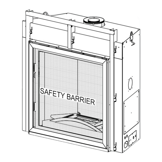
A barrier designed to reduce the risk of burns from
the hot viewing glass is provided with this appliance
and shall be installed for the protection of children
and other at-risk individuals.
BARRIER
103 Miller Drive, Crittenden, Kentucky, USA, 41030
HDX35NT
NATURAL GAS
HDX35PT
PROPANE
DANGER
!
HOT GLASS WILL CAUSE
BURNS.
DO NOT TOUCH GLASS UNTIL
COOLED.
NEVER ALLOW CHILDREN TO
TOUCH GLASS.
1.28F
EN
FR
PG
65
W415-1434 / 06.09.15
Publicité
Chapitres
Table des Matières
Dépannage

Manuels Connexes pour Napoleon HDX35NT


Sommaire des Matières pour Napoleon HDX35NT
- Page 1 BARRIER Wolf Steel Ltd., 24 Napoleon Rd., Barrie, ON, L4M 0G8 Canada / 103 Miller Drive, Crittenden, Kentucky, USA, 41030 Phone (705)721-1212 • Fax (705)722-6031 • www.napoleonfi replaces.com • hearth@napoleonproducts.com $10.00...
-
Page 2: Table Des Matières
TABLE OF CONTENTS The camera icon indicates video tutorials are available as additional reference, visit http://www.napoleonfi replaces.com/category/product-support/support-centre/ INSTALLATION OVERVIEW INTRODUCTION DIMENSIONS GENERAL INSTRUCTIONS GENERAL INFORMATION RATING PLATE INFORMATION VENTING VENTING LENGTHS AND COMPONENTS TYPICAL VENT INSTALLATION VENT TERMINAL CLEARANCES VENT APPLICATION FLOW CHART... -
Page 3: Installation Overview
1.0 INSTALLATION OVERVIEW See the section “VENTING - VENTING LENGTHS AND AIR TERMINAL LOCATIONS” See the section “FRAMING - MINIMUM MANTEL CLEARANCES” See the section “FRAMING” See the section See the section “FRAMING - MINIMUM “FRAMING - MINIMUM CLEARANCE TO CLEARANCE TO COMBUSTIBLE COMBUSTIBLE... -
Page 4: Introduction
2.0 INTRODUCTION WARNING • THIS APPLIANCE IS HOT WHEN OPERATED AND CAN CAUSE SEVERE BURNS IF CONTACTED. • ANY CHANGES OR ALTERATIONS TO THIS APPLIANCE OR ITS CONTROLS CAN BE DANGEROUS AND IS PROHIBITED. • Do not operate appliance before reading and understanding operating instructions. Failure to operate appliance according to operating instructions could cause fi... -
Page 5: Dimensions
DIMENSIONS 20 1/8" 512mm 40 1/8" 1019mm 30 7/8" 785mm 38 7/16" 977mm 42 3/4" 1085mm 5 5/8" SAFETY BARRIER 143mm 32 3/4" 831mm Ø 7" Ø 4" 178mm 102mm 2" 51mm 43 3/8" 1101mm 19 1/8" 486mm 34 5/16" 871mm GENERAL INSTRUCTIONS WARNING ALWAYS LIGHT THE PILOT WHETHER FOR THE FIRST TIME OR IF THE GAS SUPPLY HAS RUN OUT,... -
Page 6: General Information
The installation must conform with local codes or, in absence of local codes, the National Gas and Propane We suggest that our gas Installation Code CSA B149.1 in Canada, or the National Fuel Gas Code, ANSI Z223.1 / NFPA 54 in the United hearth products be installed States. -
Page 7: Rating Plate Information
HDX35 60HZ. MOINS DE 12 AMPÈRES. W385-2000 24 NAPOLEON ROAD, BARRIE, ON, L4M 0G8 CANADA ANADA INSTALLER: It is your responsibility to check off the appropriate box on the rating plate according to the model, venting and gas type of the appliance. -
Page 8: Venting
3.0 VENTING WARNING RISK OF FIRE, MAINTAIN SPECIFIED AIR SPACE CLEARANCES TO VENT PIPE AND APPLIANCE. IF VENTING IS INCLUDED WITH SPACERS THE VENT SYSTEM MUST BE SUPPORTED EVERY 3FT (0.9m) FOR BOTH VERTICAL AND HORIZONTAL RUNS. USE SUPPORTS OR EQUIVALENT NON-COMBUSTIBLE STRAPPING TO MAINTAIN THE REQUIRED CLEARANCE FROM COMBUSTIBLES. -
Page 9: Venting Lengths And Components
VENTING LENGTHS AND COMPONENTS Use only Wolf Steel, Simpson Dura-Vent, Selkirk Direct Temp, American Metal Amerivent or Metal-Fab venting components. Minimum and maximum vent lengths, for both horizontal and vertical installations, and air terminal locations for either system are set out in this manual and must be adhered to. For Simpson Dura-Vent, Selkirk Direct Temp, American Metal Amerivent and Metal-Fab follow the installation procedure provided with the venting components. -
Page 10: Typical Vent Installation
TYPICAL VENT INSTALLATION 16″ (406mm) MINIMUM WARNING! THE FIRST TWO FEET OF OUTER 7" (178MM) DIAMETER VENT PIPE FROM THE APPLIANCE MUST BE WRAPPED IN THE 1" (25MM) THICK INSULATION SLEEVE (SUPPLIED). 40 FEET (12m) MAXIMUM 3 FEET (0.9m) 18" (457mm) MINIMUM MAXIMUM INSULATED... -
Page 11: Vent Terminal Clearances
VENT TERMINAL CLEARANCES COVERED BALCONY APPLICATIONS ††* = 3 feet = 2 x ACTUAL (0.9m) (4.6m) INSTALLATIONS CANADA U.S.A. 12” (305mm) 12” (305mm) Clearance above grade, veranda porch, deck or balcony. 9” 12” (305mm) Clearance to windows or doors that open. Δ... -
Page 12: Vent Application Flow Chart
VENT APPLICATION FLOW CHART TOP EXIT Horizontal Termination Vertical Termination Vertical rise is equal Vertical rise is equal Vertical rise is less Vertical rise is less to or greater than to or greater than than horizontal run than horizontal run the horizontal run the horizontal run Horizontal run +... -
Page 13: Horizontal Termination
HORIZONTAL TERMINATION ) < (V Simple venting confi guration (only one 90° elbow) See graph to determine the required vertical rise V for the required horizontal run H 40 (12.2) 39 (11.9) REQUIRED 30 (9.1) VERTICAL RISE IN FEET 20 (6.1) (METERS)V 10 (3.1) 14"... - Page 14 ) > (V See graph to determine the required vertical rise V for the Simple venting configuration (only one 90° elbow) required horizontal run H 150 (3810) (3733.8) REQUIRED VERTICAL RISE 100 (2540) IN INCHES (MILLIMETERS) 57 (1447.8) 50 (1270) 14"...
-
Page 15: Vertical Termination
VERTICAL TERMINATION ) < (V Simple venting configurations. See graph to determine the required vertical rise V for the required horizontal run H 40 (12.2) 30 (9.1) REQUIRED VERTICAL RISE IN FEET 20 (6.1) (METERS) V 10 (3.1) 3 (0.9) (1.5) (3.1) (4.6) - Page 16 ) > (V Simple venting configurations. See graph to determine the required vertical rise V for the required horizontal run H 20 (6.1) 19 (5.8) REQUIRED VERTICAL RISE IN FEET 10 (3.1) (METERS) V 3 (0.9) 14" (356mm) (5.5) (7.6) (9.1) (1.5) (3.1)
-
Page 17: Installation
4.0 INSTALLATION WARNING ENSURE TO UNPACK ALL LOOSE MATERIALS FROM INSIDE THE FIREBOX PRIOR TO HOOKING UP THE GAS AND ELECTRICAL SUPPLY. IF YOUR APPLIANCE IS SUPPLIED WITH A REMOTE ENSURE THE REMOTE RECEIVER IS IN THE “OFF” POSITION PRIOR TO HOOKING UP THE GAS AND ELECTRICAL SUPPLY TO THE APPLIANCE. FOR SAFE AND PROPER OPERATION OF THE APPLIANCE, FOLLOW THE VENTING INSTRUCTIONS EXACTLY. -
Page 18: Horizontal Installation
4.1.1 HORIZONTAL INSTALLATION WARNING THE FIRESTOP ASSEMBLY MUST BE INSTALLED WITH THE VENT SHIELD TO THE TOP. TERMINALS MUST NOT BE RECESSED INTO A WALL OR SIDING MORE THAN THE DEPTH OF THE RETURN FLANGE OF THE MOUNTING PLATE. This application occurs when venting through an exterior wall. Having determined the correct height for the air terminal location, cut and frame a hole in the exterior wall as VENT... -
Page 19: Using Flexible Vent Components
USING FLEXIBLE VENT COMPONENTS WARNING DO NOT ALLOW THE INNER FLEX PIPE TO BUNCH UP ON HORIZONTAL OR VERTICAL RUNS AND ELBOWS. KEEP IT PULLED TIGHT. SPACERS ARE ATTACHED TO THE INNER FLEX PIPE AT PREDETERMINED INTERVALS TO MAINTAIN AN EVEN AIR GAP TO THE OUTER FLEX PIPE. -
Page 20: Vertical Air Terminal Installation
4.2.2 VERTICAL AIR TERMINAL INSTALLATION WARNING MAINTAIN A MINIMUM 2” (51mm) SPACE BETWEEN THE AIR INLET BASE AND THE STORM COLLAR. Fasten the roof support to the roof using the screws provided. The roof support is optional. In this case the venting is to be adequately supported using either an alternate method suitable to the authority having jurisdiction or the optional roof support. -
Page 21: Appliance Vent Connection
4.2.3 APPLIANCE VENT CONNECTION Install the inner exhaust fl ue collar to the appliance. Secure #8 X 1/2” with 3 screws. Seal the joint and screw holes using the high SELF temperature sealant Mill-Pac W573-0007 (not supplied). DRILLING SCREWS Install the outer fl ex pipe to the appliance. Attach and seal the 2”... -
Page 22: Gas Installation
GAS INSTALLATION WARNING RISK OF FIRE, EXPLOSION OR ASPHYXIATION. ENSURE THERE ARE NO IGNITION SOURCES SUCH AS SPARKS OR OPEN FLAMES. SUPPORT GAS CONTROL WHEN ATTACHING GAS SUPPLY PIPE TO PREVENT DAMAGING GAS LINE. ALWAYS LIGHT THE PILOT WHETHER FOR THE FIRST TIME OR IF THE GAS SUPPLY HAS RUN OUT WITH THE GLASS DOOR OPENED OR REMOVED. -
Page 23: Framing
5.0 FRAMING WARNING RISK OF FIRE! IN ORDER TO AVOID THE POSSIBILITY OF EXPOSED INSULATION OR VAPOUR BARRIER COMING IN CONTACT WITH THE APPLIANCE BODY, IT IS RECOMMENDED THAT THE WALLS OF THE APPLIANCE ENCLOSURE BE “FINISHED” (IE: DRYWALL / SHEETROCK), AS YOU WOULD FINISH ANY OTHER OUTSIDE WALL OF A HOME. - Page 24 * When constructing the enclosure allow for fi nishing material thickness to maintain clearances. IMPORTANT: Before fi nishing in the appliance test the operation using the remote control, cycling it through all of its different modes, see “OPERATION” section. Should trouble shooting be required, access to the controls can be made through the pre-fi...
- Page 25 INSIDE CHASE OUTSIDE CHASE 19 7/8" 19 7/8" [505mm] [505 mm] 43 7/8" [1114mm] 43 7/8" [1114mm] CORNER CHASE 1" [25mm] 48" [1219mm] 43 7/8" [1114mm] 70 3/4" [1797mm] W415-1434 / 06.09.15...
-
Page 26: Installing Non-Combustible Board
INSTALLING NON-COMBUSTIBLE BOARD WARNING A NON-COMBUSTIBLE FINISHING MATERIAL BORDER, SUCH AS BRICK, MARBLE, GRANITE, ETC. IS REQUIRED. FINISHING WITH JUST NON-COMBUSTIBLE BOARD TO THE SIDES AND TOP OF THE APPLIANCE IS NOT ALLOWED. THE SURFACE ABOVE THE APPLIANCE GETS VERY HOT. IF PROPER FINISHING MATERIALS ARE NOT USED, CRACKING CAN OCCUR. -
Page 27: Side View
Depending on fi nishing material thickness, the frame assembly can be adjusted out from the unit by 1 1/2" (38mm), as shown below: NOTE: Framing dimensions will vary depending on fi nishing material thickness. For recessed depths greater than 2" (51mm) refer to “NON-COMBUSTIBLE FINISHING MATERIAL” section. SIDE VIEW 1 1/2"... -
Page 28: Minimum Clearance To Combustible Enclosures
MINIMUM CLEARANCE TO COMBUSTIBLE ENCLOSURES WARNING RISK OF FIRE! THE FRONT OF THE APPLIANCE MUST BE FINISHED WITH ANY NON-COMBUSTIBLE MATERIALS SUCH AS BRICK, MARBLE, GRANITE, ETC., PROVIDED THAT THESE MATERIALS DO NOT COVER THE APPLIANCE OPENING. THE STEEL STUD FRAMING KITS WITH CEMENT BOARD PROVIDED MUST BE INSTALLED UNLESS RECESSING INTO NON-COMBUSTIBLE MATERIALS DEEPER THEN 1 1/2". -
Page 29: Clearance To Combustibles Enclosure Without Alcove
5.2.1 CLEARANCE TO COMBUSTIBLES ENCLOSURE WITHOUT ALCOVE 2" 51mm 0” IF NON-COMBUSTIBLE FINISHING MATERIAL IS USED SUCH AS BRICK AND STONE. INSULATED STEEL STUD SLEEVE FRAMING NON-COMBUSTIBLE 1" * MATERIAL 25mm 56 3/4" FIRESTOP 10" 1441mm ASSEMBLY 254mm CEILING 70" 1778mm ENCLOSURE 52 7/16"... -
Page 30: Alcove Clearance To Combustibles Enclosure
5.2.2 ALCOVE CLEARANCE TO COMBUSTIBLES ENCLOSURE NOTE: When framing with an alcove the enclosure height must be 72" (1829mm) not 70" (1778mm) 2" 51mm 0” IF NON-COMBUSTIBLE FINISHING MATERIAL INSULATED IS USED SUCH AS COMBUSTIBLE SLEEVE BRICK AND STONE. STEEL STUD 6"... -
Page 31: Minimum Combustible Mantel Clearances
MINIMUM COMBUSTIBLE MANTEL CLEARANCES WARNING RISK OF FIRE, MAINTAIN ALL SPECIFIED AIR SPACE CLEARANCES TO COMBUSTIBLES. FAILURE TO COMPLY WITH THESE INSTRUCTIONS MAY CAUSE A FIRE OR CAUSE THE APPLIANCE TO OVERHEAT. ENSURE ALL CLEARANCES (I.E. BACK, SIDE, TOP, VENT, MANTEL, FRONT, ETC.) ARE CLEARLY MAINTAINED. -
Page 32: Non-Combustible Finishing Material
NON-COMBUSTIBLE FINISHING MATERIAL WARNING: The appliance opening may be recessed in non-combustible facing material provided it does not project more than 2" (51mm) past the face of the appliance. If greater projections are desired, increase the clearance to the sides and top by 2" (51mm) for every additional 1" (25mm) of projection. If using an optional surround, then 2"... -
Page 33: Finishing
6.0 FINISHING WARNING RISK OF FIRE! NEVER OBSTRUCT THE FRONT OPENING OF THE APPLIANCE. THE FRONT OF THE APPLIANCE MUST BE FINISHED WITH ANY NON-COMBUSTIBLE MATERIALS SUCH AS BRICK, MARBLE, GRANITE, ETC., PROVIDED THAT THESE MATERIALS DO NOT GO BELOW THE SPECIFIED DIMENSION AS ILLUSTRATED. DO NOT STRIKE, SLAM OR SCRATCH GLASS. -
Page 34: Latch Door Removal / Installation
LATCH DOOR REMOVAL / INSTALLATION There are 4 spring latches securing the main glass door, 2 of those latches are across the top and 2 along the bottom. To access these latches ensure the screen is removed. Using the tool provided, pull the latch forward and upwards / downwards, out of the slot in the door, as shown. -
Page 35: Glass Door Removal / Installation
GLASS DOOR REMOVAL / INSTALLATION Release the 4 door latches from the top and bottom of the door. Refer to ‘LATCH DOOR REMOVAL / INSTALLATION’ section. Slide the glass door forward from the unit. It will sit on the door slides attached to the unit, refer to Figure 1. -
Page 36: Burner Installation
BURNER INSTALLATION See instructions accompanying burner assembly (sold separately). LOGO PLACEMENT SAFETY BARRIER LOGO W415-1434 / 06.09.15... -
Page 37: Electrical Information
7.0 ELECTRICAL INFORMATION WARNING ENSURE TO UNPACK ALL LOOSE MATERIALS FROM INSIDE THE FIREBOX PRIOR TO HOOKING UP THE GAS AND ELECTRICAL SUPPLY. IF YOUR APPLIANCE IS SUPPLIED WITH A REMOTE ENSURE THE REMOTE RECEIVER IS IN THE “OFF” POSITION PRIOR TO HOOKING UP THE GAS AND ELECTRICAL SUPPLY TO THE APPLIANCE. FOR SAFE AND PROPER OPERATION OF THE APPLIANCE, FOLLOW THE VENTING INSTRUCTIONS EXACTLY. -
Page 38: Battery Holder Installation
BATTERY HOLDER INSTALLATION The battery holder must be located within 8 feet of this side of the appliance and must be accessible for programming the remote. Install 4 AA batteries, ensure that the positive and negative ends correspond with those identifi... -
Page 39: Wiring Diagram
WIRING DIAGRAM WARNING DO NOT WIRE 110 VOLTS TO THE VALVE OR WALL SWITCH. NIGHT BLOWER LIGHT NOTE: This appliance is equipped with a three-prong (grounding) plug for protection against shock hazard and should be plugged directly into a properly grounded three-prong receptacle. Do not cut or remove the grounding prong from the plug. -
Page 40: Operation
8.0 OPERATION GENERAL TRANSMITTER LAYOUT Key Lock Low Battery Alarm Low battery alarm Transmission Room Temperature CPI mode Flame ON Night Light Blower (NOT AVAILABLE WITH THIS MODEL) INITIALIZING THE TRANSMITTER/BATTERY HOLDER FOR THE FIRST TIME Install the 4 AA batteries into the Profl ame 2 battery holder, note the polarity of the batteries and insert as indicated on the cover (+/-). -
Page 41: Temperature Display
TEMPERATURE DISPLAY With the system in the “OFF” position, press the Temperature Key and the Mode Key at the same °F °C time to change from degrees F to C. Look at the LCD screen on the Transmitter to verify that a C or F is visible to the right of the Room Temperature display. -
Page 42: Night Light Dimmer Control
NIGHT LIGHT DIMMER CONTROL The auxiliary function controls the Night Light with °F °F dimmable control. Use the Mode Key to guide you to the Night Light icon. The intensity of the output can be adjusted through 6 levels. Use the UP/DOWN arrow keys to adjust the output level. -
Page 43: Low Battery / Manual Bypass
8.10 LOW BATTERY / MANUAL BYPASS The life span of the remote batteries depends on various factors: quality of the °F batteries, the number of ignitions, the number of changes to the room thermostat set point, etc. When the transmitter batteries are low, a Battery Icon will appear on the LCD display before all battery power is lost. -
Page 44: Operating Instructions
9.0 OPERATING INSTRUCTIONS WARNING IF YOU DO NOT FOLLOW THESE INSTRUCTIONS EXACTLY, A FIRE OR EXPLOSION MAY RESULT CAUSING PROPERTY DAMAGE, PERSONAL INJURY OR LOSS OF LIFE. NEVER LEAVE CHILDREN OR OTHER AT RISK INDIVIDUALS ALONE WITH THE APPLIANCE. ALWAYS LIGHT THE PILOT WHETHER FOR THE FIRST TIME OR IF THE GAS SUPPLY HAS RUN OUT WITH THE GLASS DOOR OPENED OR REMOVED. -
Page 45: Restricting Vertical Vents
RESTRICTING VERTICAL VENTS Vertical installations may display a very active fl ame. If this appearance is not desirable, the vent exit must be restricted using a restrictor vent kit. Refer to “ACCESORIES” in the “REPLACEMENTS” section for the appropriate kit. This will reduce the velocity of the exhaust gases, slowing down the fl ame pattern and creating a more traditional gentle fl... -
Page 46: Venturi Adjustment
VENTURI ADJUSTMENT This appliance has an air shutter that has been factory set open according to the chart below: Regardless of venturi orientation, closing the air shutter will cause a more yellow fl ame, but can lead to carbon- ing. Opening the air shutter will cause a more blue fl ame, but can cause fl ame lifting from the burner ports. The fl... -
Page 47: Maintenance
10.0 MAINTENANCE MAINTENANCE MAINTENANCE WARNING MAINTENANCE TURN OFF THE GAS AND ELECTRICAL POWER BEFORE SERVICING THE APPLIANCE. APPLIANCE MAY BE HOT, DO NOT SERVICE UNTIL APPLIANCE HAS COOLED. DO NOT USE ABRASIVE CLEANERS. DO NOT PAINT THE PILOT ASSEMBLY. CAUTION: Label all wires prior to disconnection when servicing controls. Wiring errors can cause improper and dangerous operation. -
Page 48: Annual Maintenance
10.1 ANNUAL MAINTENANCE WARNING THE FIREBOX BECOMES VERY HOT DURING OPERATION. LET THE APPLIANCE COOL COMPLETELY OR WEAR HEAT RESISTANT GLOVES BEFORE CONDUCTING SERVICE. NEVER VACUUM HOT EMBERS. DO NOT PAINT THE PILOT ASSEMBLY. • This appliance will require maintenance which should be planned on an annual basis. •... -
Page 49: Control Access
10.2 CONTROL ACCESS Once the appliance has been framed and fi nished, control access can only be achieved by removing the access panel from the inside right side of the fi rebox. The following sub sections take you through the steps of accessing the control as if the appliance is installed. -
Page 50: Burner Removal
10.3 BURNER REMOVAL Remove any media and/or media tray from the applaince, refer to “MEDIA TRAY REMOVAL” section. Remove the screws from the burner assembly base and carefully lift from the fi rebox. 10.4 BRICK PANEL REMOVAL Remove the 2 screws securing the brick panel brackets from the top left of the appliance. Remove the screws securing the front brick retainers. -
Page 51: Night Light™ Replacement
10.7 NIGHT LIGHT™ REPLACEMENT Your HDX35 comes equipped with a “Night Lights™”. The light has been pre-wired and is controlled from the remote control. If in the event the lamps or lens need replacing, follow the instructions below: A. Shut off breaker at main power supply B. -
Page 52: Glass / Door Replacement
NEVER ALLOW CHILDREN discoloration and / or blemishes may result. TO TOUCH GLASS. This appliance is factory equipped with 5mm ceramic glass. Use only replacement glass available from your Napoleon dealer. DO NOT SUBSTITUTE MATERIALS. 5.5.1 10.10 CARE OF PLATED PARTS If the appliance is equipped with plated parts, you must clean fi... -
Page 53: Replacements
11.0 REPLACEMENTS Contact your dealer or the factory for questions concerning prices and policies on replacement parts. Normally all parts can be ordered through your Authorized dealer / distributor. WARNING FOR WARRANTY REPLACEMENT PARTS, A PHOTOCOPY OF THE ORIGINAL INVOICE WILL BE REQUIRED TO HONOUR THE CLAIM. FAILURE TO POSITION THE PARTS When ordering replacement parts always give the following information: IN ACCORDANCE WITH THIS... - Page 54 W415-1434 / 06.09.15...
- Page 55 W415-1434 / 06.09.15...
- Page 56 W415-1434 / 06.09.15...
- Page 57 W415-1434 / 06.09.15...
- Page 58 W415-1434 / 06.09.15...
-
Page 59: Troubleshooting
17.0 TROUBLESHOOTING WARNING ALWAYS LIGHT THE PILOT WHETHER FOR THE FIRST TIME OR IF THE GAS SUPPLY HAS RUN OUT, WITH THE GLASS DOOR OPEN OR REMOVED. TURN OFF THE GAS AND ELECTRICAL POWER BEFORE SERVICING THE APPLIANCE. APPLIANCE MAY BE HOT, DO NOT SERVICE UNTIL APPLIANCE HAS COOLED. DO NOT USE ABRASIVE CLEANERS. - Page 60 SYMPTOM PROBLEM TEST SOLUTION White / grey fi lm Sulphur from fuel is being Clean the glass with a recommended gas fi replace forms. deposited on glass, logs glass cleaner. DO NOT CLEAN GLASS WHEN HOT. or combustion chamber If deposits are not cleaned off regularly, the glass surfaces.
- Page 61 SYMPTOM PROBLEM TEST SOLUTION Pilot sparks but Gas supply. Verify that the incoming gas line ball valve is “Open”. will not light. Verify that the inlet pressure reading is within acceptable limits, inlet pressures must not exceed 14” W.C. (34.9mb). Module is not grounded.
-
Page 62: Warranty
All parts replaced under the President’s Limited Lifetime Warranty Policy are subject to a single claim. During the fi rst 10 years NAPOLEON will replace or repair the defective parts covered by the lifetime warranty at our discretion free of charge. From 10 years to life, NAPOLEON will provide replacement parts at 50% of the current retail price. -
Page 63: Service History
19.0 SERVICE HISTORY 43.1 W415-1434 / 06.09.15... - Page 64 napoleonproducts.com...
-
Page 65: Consignes De Sécurité
à risque. ÉCRAN DE PROTECTION N° de série N° DE MODÈLE Wolf Steel Ltd., 24 Napoleon Rd., Barrie, ON, L4M 0G8 Canada / 103 Miller Drive, Crittenden, Kentucky, USA, 41030 Téléphone 705-721-1212 • Télécopieur 705-722-6031 • www.napoleonfoyers.com • hearth@napoleonproducts.com 10,00$ 1.28D... - Page 66 TABLE DES MATIÈRES NOTE: L’icône du camera indique que les vidéos sont disponibles comme une référence supplémentaire, visitez http://www.napoleonfi replaces.com/category/product-support/support-centre/ SURVOL DE L’INSTALLATION INTRODUCTION DIMENSIONS INSTRUCTIONS GÉNÉRALES INFORMATION GÉNÉRALE INFORMATION SUR LA PLAQUE D’HOMOLOGATION ÉVACUATION LONGUEURS ET COMPOSANTS DES CONDUITS D’ÉVACUATION INSTALLATIONS TYPIQUES D’ÉVENTS...
-
Page 67: Survol De L'installation
1.0 SURVOL DE L’INSTALLATION Voir la section « ÉVACUATION - LONGUEURS DES CONDUITS D’ÉVACUATION ET EMPLACEMENTS DE LA TER- MINAISON » Voir la section « OSSATURE - DÉGAGEMENTS MINIMAUX DE LA TABLETTE » Voir la section « OSSATURE » Voir la section Voir la section «... -
Page 68: Introduction
2.0 INTRODUCTION AVERTISSEMENT • CET APPAREIL EST CHAUD LORSQU’IL FONCTIONNE ET PEUT CAUSER DE GRAVES BRÛLURES EN CAS DE CONTACT. • TOUTE MODIFICATION APPORTÉE À CET APPAREIL OU AUX CONTRÔLES PEUT ÊTRE DANGEREUX ET EST INTERDIT. • Ne faites pas fonctionner l’appareil avant d’avoir lu et compris les instructions d’opération. Omettre d’utiliser l’appareil selon les instructions d’opération pourrait causer un incendie ou des blessures. -
Page 69: Dimensions
DIMENSIONS 20 1/8" 512mm 40 1/8" 1019mm 30 7/8" 785mm 38 7/16" 977mm 42 3/4" 1085mm 5 5/8" ÉCRAN DE PROTECTION SAFETY BARRIER 143mm 32 3/4" 831mm Ø 7" Ø 4" 178mm 102mm 2" 51mm 19 1/8" 486mm 43 3/8" 1101mm 34 5/16"... -
Page 70: Information Générale
Tant que les distances requises pour les dégagements aux matériaux combustibles sont respectées, le meilleur endroit pour un appareil est le Nous suggérons que nos centre de la maison, car ceci permet une meilleure utilisation de la chaleur appareils au gaz soient installés fournie. -
Page 71: Information Sur La Plaque D'homologation
SERIAL NUMBER/ NO. DE SÉRIE: HDX35 60HZ. MOINS DE 12 AMPÈRES. W385-2000 24 NAPOLEON ROAD, BARRIE, ON, L4M 0G8 CANADA ON ROAD, BARRIE, O ON ROAD, BARRIE, INSTALLATEUR : Il est de votre responsabilité de cocher les cases appropriées sur la plaque d’homologation correspondant au modèle, au type d’évacuation et au type de gaz de l’appareil. -
Page 72: Évacuation
3.0 ÉVACUATION AVERTISSEMENT RISQUE D’INCENDIE. CONSERVEZ LES DÉGAGEMENTS NÉCESSAIRES AU CONDUIT D’ÉVENT ET À L’APPAREIL. SI LE SYSTÈME D’ÉVENT EST FOURNI AVEC DES ESPACEURS, LES COURSES HORIZONTALES ET VERTICALES DU SYSTÈME DOIVENT ÊTRE SUPPORTÉES À TOUS LES 3 PI (0,9m). UTILISEZ DES SUPPORTS OU DES ATTACHES INCOMBUSTIBLES ÉQUIVALENTS AFIN DE MAINTENIR LE DÉGAGEMENT AUX MATÉRIAUX COMBUSTIBLES. -
Page 73: Longueurs Et Composants Des Conduits D'évacuation
LONGUEURS ET COMPOSANTS DES CONDUITS D’ÉVACUATION Utilisez uniquement des composants d’évacuation Wolf Steel, Simpson Dura-Vent, Selkirk Direct Temp, American Metal Amerivent ou Metal-Fab. Les minimums et maximums des longueurs d’évent, pour les installations verticales et horizontales, et les emplacements des terminaisons pour les deux systèmes sont précisés dans ce manuel et doivent être respectés. -
Page 74: Installations Typiques D'évents
INSTALLATIONS TYPIQUES D’ÉVENTS 16" (406mm) MINIMUM AVERTISSMENT! LE PREMIER DEUX PIEDS DE CONDUIT EXTÉRIEUR DE 7” DE DIAMÈTRE À PARTIR DE L’APPA-REIL DOIT ÊTRE ENVELOPPÉ DANS UN MANCHON ISOLANT DE 1” (25MM) D’ÉPAISSEUR (FOURNI). 40 FEET (12m) MAXIMUM 3 FEET (1m) 18"... -
Page 75: Emplacements Et Dégagements Minimaux De La Terminaison
EMPLACEMENTS ET DÉGAGEMENTS MINIMAUX DE LA TERMINAISON ††* APPLICATIONS POUR BALCON COUVERT INSTALLATION = 3 pieds = 2 x RÉELLE (0,9m) (4,6m) CANADA É.-U. 12” 12” Dégagement au-dessus du sol, d’une véranda, d’une terrasse en bois ou d’un balcon. (304,8mm) (304,8mm) 12”... -
Page 76: Charte D'application Des Évacuations
CHARTE D’APPLICATION DES ÉVACUATIONS ÉVACUATION SUR LE DESSUS Terminaison horizontale Terminaison verticale La course verticale La course verticale La course verticale La course verticale est plus grande ou est plus grande ou est plus petite est plus petite égale à la course égale à... -
Page 77: Terminaison Horizontale
TERMINAISON HORIZONTALE ) < (V Configuration d'évacuation simple (un coude de 90° Consultez le graphique pour déterminer la course verticale seulement). nécessaire V par rapport à la course horizontale requise H 40 (12,2) 39 (11,9) 30 (9,1) COURSE VERTICALE REQUISE EN 20 (6,1) PIEDS (MÈTRES) V... - Page 78 ) > (V Consultez le graphique pour déterminer la course verticale Configuration d'évacuation simple (un coude de 90° nécessaire V par rapport à la course horizontale requise H seulement). 150 (3810) 147 (3733.8) COURSE 100 (2540) VERTICALE REQUISE EN POUCES (MILLIMÈTRES) V 57 (1447.8) 50 (1270)
-
Page 79: Terminaison Verticale
TERMINAISON VERTICALE ) < (V Configuration d'évacuation simple. Consultez le graphique pour déterminer la course verticale nécessaire V par rapport à la course horizontale requise H 40 (12,2) 30 (9,1) COURSE VERTICALE REQUISE EN 20 (6,1) PIEDS (MÈTRES)V 10 (3,1) 3 (0,9) (1,5) (3,1) - Page 80 ) > (V Configuration d'évacuation simple. Consultez le graphique pour déterminer la course verticale nécessaire V par rapport à la course horizontale requise H 20 (6,1) 19 (5,8) COURSE VERTICALE REQUISE EN 10 (3,1) PIEDS (MÈTRES) V 3 (0,9) 18" (457mm) (7,6) (9,1) (1,5)
-
Page 81: Installation
4.0 INSTALLATION AVERTISSEMENT AVANT D’EFFECTUER LES BRANCHEMENTS POUR L’ALIMENTATION EN GAZ ET ÉLECTRIQUE, ASSUREZ-VOUS DE RETIRER TOUTE COMPOSANTE NON FIXÉE À L’INTÉRIEUR DE LA CHAMBRE DE COMBUSTION. SI VOTRE APPAREIL COMPREND UN SYSTÈME DE TÉLÉCOMMANDE, ASSUREZ-VOUS QUE LE RÉCEPTEUR EST À LA POSITION « OFF » AVANT D’EFFECTUER LES BRANCHEMENTS POUR L’ALIMENTATION EN GAZ ET ÉLECTRIQUE. -
Page 82: Installation Horizontale
4.1.1 INSTALLATION HORIZONTALE AVERTISSEMENT L’ESPACEUR COUPE-FEU DOIT ÊTRE INSTALLÉ AVEC L’ÉCRAN PROTECTEUR ORIENTÉ VERS LE HAUT. LA TERMINAISON NE DOIT PAS ÊTRE ENCHÂSSÉE DANS LE MUR OU LE REVÊTEMENT EXTÉRIEUR PLUS QUE L’ÉPAISSEUR DE LA BRIDE DE LA PLAQUE DE MONTAGE. Cette confi... -
Page 83: Utilisation De Composants Flexibles D'évacuation
UTILISATION DE COMPOSANTS FLEXIBLES D’ÉVACUATION AVERTISSEMENT NE LAISSEZ PAS LA GAINE FLEXIBLE SE TASSER CONTRE LES COURSES HORIZONTALES OU VERTICALES ET LES COUDES. GARDEZ-LA TENDUE. DES ESPACEURS SONT FIXÉS À LA GAINE FLEXIBLE À INTERVALLES PRÉDÉTERMINÉS AFIN DE GARDER UN ESPACE VIDE AVEC LE CONDUIT EXTÉRIEUR. POUR QUE LE FONCTIONNEMENT SOIT SÉCURITAIRE, UN ESPACE VIDE EST REQUIS. -
Page 84: Installation De La Terminaison Verticale
4.2.2 INSTALLATION DE LA TERMINAISON VERTICALE AVERTISSEMENT CONSERVEZ UN ESPACE MINIMAL DE 2" (50,8mm) ENTRE LA BASE DE LA PRISE D’AIR ET LE COLLET DE SOLIN. Fixez le support de toit au toit à l’aide des vis fournies. Le support de toit est optionnel. -
Page 85: Raccordement Des Évents À L'appareil
4.2.3 RACCORDEMENT DES ÉVENTS À L’APPAREIL Raccordez la collet d’évacuation à l’appareil. Fixez-la à l’aide de trois vis. Scellez le joint et les têtes de vis avec AUTOPER- le scellant à haute température Mill-Pac W573-0007 (non CEUSES fourni). #8 X 1/2” CHEVAUCHEMENT DE 2”... -
Page 86: Branchement Du Gaz
BRANCHEMENT DU GAZ AVERTISSEMENT RISQUE D'INCENDIE, D'EXPLOSION OU D'ASPHYXIE. ASSUREZ-VOUS QU'IL N'Y AIT AUCUNE SOURCE D'ALLUMAGE COMME DES ÉTINCELLES OU UNE FLAMME NUE. SOUTENEZ LE CONTRÔLE DU GAZ LORSQUE VOUS ATTACHEZ LE TUYAU POUR ÉVITER DE PLIER LA CON- DUITE DE GAZ. ALLUMEZ TOUJOURS LA VEILLEUSE, QUE CE SOIT POUR LA PREMIÈRE FOIS OU LORSQUE L’APPROVISIONNEMENT EN GAZ EST ÉPUISÉ, AVEC LA PORTE VITRÉE OUVERTE OU RETIRÉE. -
Page 87: Ossature
5.0 OSSATURE AVERTISSEMENT RISQUE D’INCENDIE! AFIN D’ÉVITER LA POSSIBILITÉ QUE DE L’ISOLATION OU UN COUPE-VAPEUR ENTRENT EN CON- TACT AVEC L’EXTÉRIEUR DU CAISSON, IL EST CONSEILLÉ D’INSTALLER L’APPAREIL CONTRE DES MURS FINIS (C.-À-D. PANNEAU DE GYPSE) COMME TOUT AUTRE MUR DE LA MAISON. CECI ASSURERA QUE LE DÉGAGEMENT AUX MATÉRIAUX COMBUSTIBLES EST MAINTENU. - Page 88 * Lorsque vous construisez l’enceinte, prévoyez l’épaisseur des matériaux de fi nition pour maintenir les dégagements. IMPORTANT : Avant d’effectuer la fi nition, vérifi ez le fonctionnement de l’appareil à l’aide de la télécommande en testant chacun des différents modes. Voir la section « FONCTIONNEMENT ». Si un dépannage s’avère nécessaire, l’accès aux contrôles peut se faire par le panneau d’accès de préinstallation.
- Page 89 ENCEINTE EXTÉRIEURE ENCEINTE INTÉRIEURE 19 7/8" 19 7/8" [505mm] [505 mm] 43 7/8" [1114mm] 43 7/8" [1114mm] ENCEINTE COIN 1" [25mm] 48" [1219mm] 43 7/8" [1114mm] 70 3/4" [1797mm] W415-1434 / 06.19.15...
-
Page 90: Installation Du Matériaux Incombustible
INSTALLATION DU MATÉRIAUX INCOMBUSTIBLE AVERTISSEMENT UNE FINITION INCOMBUSTIBLE COMME DE LA BRIQUE, DU MARBRE, DU GRANITE, ETC. EST REQUISE. IL EST INTERDIT D’UTILISER SEULEMENT DES PANNEAUX DE INCOMBUSTIBLES POUR LA FINITION DES CÔTÉS ET DU DESSUS DE L’APPAREIL. LA SURFACE AU-DESSUS DE L’APPAREIL DEVIENT TRÈS CHAUDE. SI DES MATÉRIAUX DE FINITION INADÉQUATS SONT UTILISÉS, DES CRAQUELURES PEUVENT APPARAÎTRE. - Page 91 Selon les matériaux de fi nition, l’assemblage de châssis peut être réglé à partir de l’unité de 1 3/4 “(44mm), comme indiqué ci-dessous: NOTE: Dimensions d’encadrement varient en fonction de l’épaisseur du matériau de fi nition. Pour des profondeurs supérieures à 2" (51mm) référer la section “MATÉRIAU DE FINITION INCOMBUSTIBLE”. VUE DU CÔTÉ...
-
Page 92: Dégagements Minimaux Aux Enceintes Combustibles
DÉGAGEMENTS MINIMAUX AUX ENCEINTES COMBUSTIBLES AVERTISSEMENT RISQUE D’INCENDIE. CONSERVEZ TOUS LES DÉGAGEMENTS AUX MATÉRIAUX COMBUSTIBLES SPÉCIFIÉS. NE PAS RESPECTER CES INSTRUCTIONS PEUT CAUSER UN INCENDIE OU UNE SURCHAUFFE. ASSUREZ-VOUS QUE TOUS LES DÉGAGEMENTS (ARRIÈRE, CÔTÉS, DESSUS, ÉVENTS, TABLETTE, FAÇADE, ETC.) SONT RESPECTÉS À LA LETTRE. LORSQUE VOUS UTILISEZ DE LA PEINTURE OU DU VERNIS COMME FINITION POUR VOTRE TABLETTE, ASSUREZ-VOUS QU’ILS SOIENT RÉSISTANTS À... -
Page 93: Dégagements Minimaux Aux Enceintes Combustibles Sans Alcôve
5.2.1 DÉGAGEMENTS MINIMAUX AUX ENCEINTES COMBUSTIBLES SANS ALCÔVE 2" 51mm MANCHON DE OSSATURE AVEC ISOLANT POTEAUX EN ACIER MATÉRIAU 1" * INCOMBUSTIBLE 25mm L’ A SSEMBLAGE 56 3/4" DE L’ESPACEUR 10" 1441mm 254mm COUPE-FEU PLAFOND 70" 1778mm HAUTEUR ENCEINTE 42 3/4" 52 7/16"... -
Page 94: Dégagements Minimaux Aux Enceintes Combustibles Avec Alcôve
5.2.2 DÉGAGEMENTS MINIMAUX AUX ENCEINTES COMBUSTIBLES AVEC ALCÔVE NOTE: Lorsque de l’élaboration d’une alcôve, la hauteur de l’enceinte doit être 72" (1829mm) pas 70" (1778mm). 2" 51mm MANCHON DE ISOLANT COMBUSTIBLE OSSATURE AVEC POTEAUX 6" EN ACIER 152mm MATÉRIAU 2" 1"... -
Page 95: Dégagements Minimaux De La Tablette
DÉGAGEMENTS MINIMAUX DE LA TABLETTE AVERTISSEMENT RISQUE D’INCENDIE. CONSERVEZ TOUS LES DÉGAGEMENTS AUX MATÉRIAUX COMBUSTIBLES SPÉCIFIÉS. NE PAS RESPECTER CES INSTRUCTIONS PEUT CAUSER UN INCENDIE OU UNE SURCHAUFFE. ASSUREZ-VOUS QUE TOUS LES DÉGAGEMENTS (ARRIÈRE, CÔTÉS, DESSUS, ÉVENTS, TABLETTE, FAÇADE, ETC.) SONT RESPECTÉS À LA LETTRE. LORSQUE VOUS UTILISEZ DE LA PEINTURE OU DU VERNIS COMME FINITION POUR VOTRE TABLETTE, ASSUREZ-VOUS QU’ILS SOIENT RÉSISTANTS À... -
Page 96: Matériau De Finition Incombustible
MATÉRIAU DE FINITION INCOMBUSTIBLE AVERTISSEMENT: L'ouverture de l'appareil peut être encastré dans le matériaux de finition incombustibles à condition ne pas dépasser de plus de 2" (51mm)la façade de la porte (sur toutes côtés). Si des projections plus grandes sont requises, augmentez les dégagements des côtés et du dessus de 2"... -
Page 97: Finition
6.0 FINITION AVERTISSEMENT RISQUE D’INCENDIE! N’OBSTRUEZ JAMAIS L’OUVERTURE SUR LE DEVANT DE L’APPAREIL. LA FAÇADE DE L’APPAREIL DOIT ÊTRE FAITE DE MATÉRIAUX INCOMBUSTIBLES COMME DE LA BRIQUE, DU MARBRE, DU GRANITE, ETC., À CONDITION QUE CES MATÉRIAUX NE SE TROUVENT PAS EN DEÇÀ... -
Page 98: Loquet De Porte
LOQUET DE PORTE Il y a 4 loquets de porte qui obtient la porte, 2 sont à travers le sommet et 2 à travers le sommet. Pour accéder à ces loquets, la porte à 4 pièces doit être enlevée. Utiliser l’outil fourni, tirer le loquet en avant et vers le haut, puis hors de l’entaille dans la porte, comme illustré. -
Page 99: Enlèvement Et Installation De La Porte Vitrée
ENLÈVEMENT ET INSTALLATION DE LA PORTE VITRÉE Déverrouillez les quatre loquets situés dans le haut et le bas de la porte, voir la section “RETRAITS DU LOQUET DE PORTE”. Glissez la porte vitrée vers l’avant. Elle reposera sur les glissières de porte fi xées à l’appareil, refer to Figure 1. -
Page 100: Installation Du Brûleur
INSTALLATION DU BRÛLEUR Voir les instructions accompagnant l’assemblage du brûleur (vendu séparément). MISE EN PLACE DU LOGO ÉCRAN DE PROTECTION SAFETY BARRIER LOGO W415-1434 / 06.19.15... -
Page 101: Branchement Électrique
7.0 BRANCHEMENT ÉLECTRIQUE AVERTISSEMENT AVANT D’EFFECTUER LES BRANCHEMENTS POUR L’ALIMENTATION EN GAZ ET ÉLECTRIQUE, ASSUREZ-VOUS DE RETIRER TOUTE COMPOSANTE NON FIXÉE À L’INTÉRIEUR DE LA CHAMBRE DE COMBUSTION. SI VOTRE APPAREIL COMPREND UN SYSTÈME DE TÉLÉCOMMANDE, ASSUREZ-VOUS QUE LE RÉCEPTEUR EST À LA POSITION « OFF » AVANT D’EFFECTUER LES BRANCHEMENTS POUR L’ALIMENTATION EN GAZ ET ÉLECTRIQUE. -
Page 102: Installation Du Récepteur
INSTALLATION DU RÉCEPTEUR Le récepteur doit être situé à une distance maximale de 8 pieds (2,4m) de ce côté de l’appareil et doit être accessible pour programmer la télécommande. Installez le récepteur dans un boîtier électrique standard. Déterminez un emplacement approprié et installez le boîtier électrique. -
Page 103: Schéma De Câblage
SCHÉMA DE CÂBLAGE AVERTISSEMENT NE RACCORDEZ PAS L’INTERRUPTEUR MURAL OU LA SOUPAPE DE GAZ À L’ALIMENTATION ÉLECTRIQUE (110 VOLTS). FUSIBLE VEILLE- SOUFFLERIE DE BLOWER COMBUSTION INTERFACE INTERFACE DIAGNOSTIQUE UTILISATEUR NOTE: Pour votre protection contre les risques de chocs électriques, cet appareil est muni d’une fi che à... -
Page 104: Fonctionnement
8.0 FONCTIONNEMENT DESSIN GÉNÉRAL DE LA TÉLÉCOMMANDE Key Lock L’alarme de faible piles Transmission Temperature du salle Mode CPI Flame Marche Veilleuse Soufflerie (PAS DISPONIBLE AVEC CE MODÈLE) PREMIÈRE INITIALISATION DE LA TÉLÉCOMMANDE/BLOC-PILES Installez 4 piles AA dans le bloc-piles du Profl ame 2, notez la polarité des piles puis insérez-les comme indiqué... -
Page 105: Afficheur De Température
AFFICHEUR DE TEMPÉRATURE Avec le système en position «OFF», appuyez °F °C simultanément sur les touches «TEMPÉRATURE» et « MODE » pour passer de l’affi chage de la température en Fahrenheit à Celsius. Vérifi ez l’affi cheur ACL de la télécommande pour vous assurer que le C ou le F est visible à... -
Page 106: Hauteur De La Flamme
HAUTEUR DE LA FLAMME La télécommande comporte six (6) niveaux de fl ammes. °F °F Avec le système en marche et le niveau de la fl amme au maximum, appuyez une fois sur la touche bas et cela réduira la hauteur de la fl amme d’un niveau jusqu’à... -
Page 107: Fonction De Sécurité Pour Enfants
FONCTION DE SÉCURITÉ POUR ENFANTS Cette fonction verrouillera les touches pour empêcher une utilisation non supervisée. °F Appuyez simultanément sur les touches « MODE » et haut. Pour désactiver cette fonction, appuyez simultanément sur les touches «MODE» et haut. 35.10A 8.10 FAIBLE PILES/LE BY-PASS MANUEL La durée de vie des piles peut dépendre de plusieurs facteurs : la qualité... -
Page 108: Instructions De Fonctionnement
9.0 INSTRUCTIONS DE FONCTIONNEMENT AVERTISSEMENT SI CES INSTRUCTIONS NE SONT PAS SUIVIES À LA LETTRE, UN FEU OU UNE EXPLOSION POURRAIENT S’ENSUIVRE, CAUSANT DES DOMMAGES MATÉRIELS, DES BLESSURES COR- PORELLES OU DES PERTES DE VIE. ALLUMEZ TOUJOURS LA VEILLEUSE, QUE CE SOIT POUR LA PREMIÈRE FOIS OU LORSQUE L’APPROVISIONNEMENT EN GAZ EST ÉPUISÉ, AVEC LA PORTE VITRÉE OUVERTE OU RETIRÉE. -
Page 109: Étranglements Des Évents Verticaux
ÉTRANGLEMENTS DES ÉVENTS VERTICAUX Certaines confi gurations d’évacuation verticales peuvent avoir une fl amme très active. Si cette apparence n’est pas désirée, la sortie du conduit d’évacuation doit être réduite en utilisant une plaque de restriction. Pour obtenir l’ensemble approprié, voir les « ACCESSOIRES » à la section « RECHANGES ». Ceci diminuera la vélocité... -
Page 110: Réglage Du Venturi
RÉGLAGE DU VENTURI L’ouverture du volet d’air a été préréglée en usine selon le tableau ci-dessous : Indépendamment de l’orientation du venturi, plus le volet est fermé, plus la fl amme est jaune et aura tendance à causer des dépôts de carbone. Plus le volet est ouvert, plus la fl... -
Page 111: Entretien
10.0 ENTRETIEN AVERTISSEMENT COUPEZ L’ALIMENTATION EN GAZ ET L’ALIMENTATION ÉLECTRIQUE AVANT DE PROCÉDER À L’ENTRETIEN DE L’APPAREIL. L’APPAREIL PEUT ÊTRE CHAUD. ATTENDEZ QU’IL SOIT REFROIDI AVANT D’EN FAIRE L’ENTRETIEN. N’UTILISEZ PAS DE PRODUITS ABRASIFS. NE PEINTURE PAS L’ASSEMBLAGE DU VEILLEUSE. ATTENTION : Lors de l’entretien des contrôles, assurez-vous d’identifi... -
Page 112: Entretien Annuel
10.1 ENTRETIEN ANNUEL AVERTISSEMENT LE CAISSON DEVIENT TRÈS CHAUD LORS DU FONCTIONNEMENT. LAISSEZ L’APPAREIL SE REFROIDIR COMPLÈTEMENT OU PORTEZ DES GANTS ANTICHALEUR AVANT D’EFFECTUER L’ENTRETIEN. NE JAMAIS ASPIRER DES BRAISES QUI SONT CHAUDES. NE PEINTUREZ PAS L’ASSEMBLAGE DE LA VEILLEUSE. •... -
Page 113: Accès Aux Contrôles
10.2 ACCÈS AUX CONTRÔLES Lorsque l’ossature et la fi nition sont terminées, l’accès aux contrôles ne peut se faire qu’en retirant à partir du côté droit de la chambre de combustion. Les sous-sections suivantes donnent les étapes à suivre pour accéder aux contrôles lorsque la fi... -
Page 114: Enlèvement Du Brûleur
10.3 ENLÈVEMENT DU BRÛLEUR Consultez le manuel du brûleur qui est expédié séparément de l’appareil. Retirez les composants décoratif et/ou plateau de composants décoratif à partir de l’appareil, référer a la section “ENLÈVEMENT DES ENSEMBLES DÉCORATIFS” Retirez les vis à partir de l’assemblage du brûleur et soulevez à partir de l’appareil. 10.4 ENLÈVEMENT DU PANNEAU DE BRIQUE Retirez les 2 vis de fi... -
Page 115: Lumière De Veille
10.7 LUMIÈRE DE VEILLE Le HDX35 est équipé une lumière de veille. Les lumière de veille sont précâblées et est contrôlées par la télécommande. Si vous devez remplacer l’ampoule ou la lentille, suivez les instructions sui-vantes : A. Désactivez le disjoncteur à l’entrée d’alimentation principale. B. -
Page 116: Remplacement De La Vitre/Porte
10.8 REMPLACEMENT DE LA VITRE/PORTE AVERTISSEMENT N’UTILISEZ PAS DE MATÉRIAUX DE SUBSTITUTION. LA VITRE PEUT ÊTRE CHAUDE, NE TOUCHEZ PAS LA VITRE JUSQU’À CE QU’ELLE AIT REFROIDI. USEZ DE PRUDENCE LORSQUE VOUS ENLEVEZ ET JETEZ DES DÉBRIS DE VERREOU DES COMPOSANTS ENDOMMAGÉS. -
Page 117: Rechanges
11.0 RECHANGES Contactez votre détaillant ou le fabricant pour les questions concernant les prix et la disponibilité des pièces de rechange. Normalement, toutes les pièces peuvent être commandées chez votre détaillant autorisé. POUR UN REMPLACEMENT DE PIÈCE SOUS GARANTIE, UNE PHOTOCOPIE DE LA FACTURE ORIGI- NALE SERA REQUISE AFIN DE POUVOIR HONORER LA DEMANDE. - Page 118 W415-1434 / 06.19.15...
- Page 119 W415-1434 / 06.19.15...
- Page 120 W415-1434 / 06.19.15...
- Page 121 W415-1434 / 06.19.15...
- Page 122 W415-1434 / 06.19.15...
-
Page 123: Guide De Dépannage
17.0 GUIDE DE DÉPANNAGE MAINTENANCE MAINTENANCE AVERTISSEMENT MAINTENANCE ALLUMEZ TOUJOURS LA VEILLEUSE, QUE CE SOIT POUR LA PREMIÈRE FOIS OU LORSQUE L’APPROVISIONNEMENT EN GAZ EST ÉPUISÉ, AVEC LA PORTE VITRÉE OUVERTE OU RETIRÉE. COUPEZ L’ALIMENTATION EN GAZ ET L’ALIMENTATION ÉLECTRIQUE AVANT DE PROCÉDER À L’ENTRETIEN DE L’APPAREIL. - Page 124 SYMPTÔME PROBLÈME SOLUTIONS On détecte l’odeur L’appareil refoule les Vérifi ez tous les joints scellés de la porte. des gaz de gaz de combustion dans Vérifi ez si la cheminée ne serait pas bloquée. combustion dans la pièce. Vérifi ez que les conduits d’évents sont installés correctement. la pièce;...
- Page 125 SYMPTÔME PROBLÈME SOLUTIONS Étincelle à la Alimentation en gaz. Vérifi ez si la soupape à bille de la conduite d’arrivée veilleuse mais du gaz est « Ouverte ». Vérifi ez si la pression celle-ci ne d’arrivée est dans les limites acceptables. La s’allume pas.
-
Page 126: Garantie
18.0 GARANTIE Les produits Napoléon® sont fabriqués conformément aux normes strictes du Certifi cat d’Assurance de la Qualité mondialement reconnu ISO 9001 : 2008. Les produits Napoléon® sont conçus avec des composants et des matériaux de qualité supérieure, assemblés par des artisans qualifi... -
Page 127: Historique D'entretien
19.0 HISTORIQUE D’ENTRETIEN 43.1 W415-1434 / 06.19.15... - Page 128 napoleonproducts.com...