Table des Matières
Publicité
Les langues disponibles
Les langues disponibles
Liens rapides
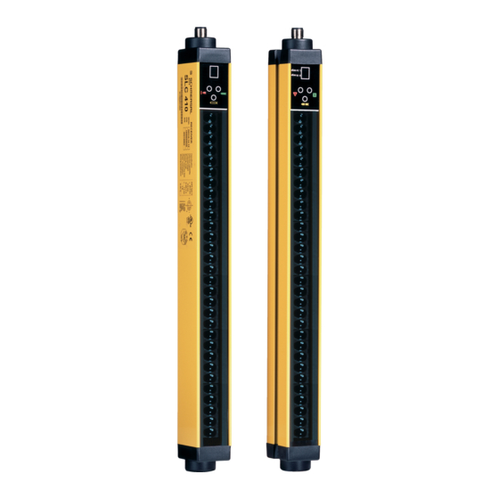
Lichtvorhänge / Lichtgitter
SLC 210 / SLG 210 RFLC
M
o
n
t
a
g
M
o
n
t
a
g
M
o
u
n
t
i
M
o
u
n
t
i
I
n
s
t
r
u
c
t
i
o
n
s
I
n
s
t
r
u
c
t
i
o
n
s
Sicherheits-
e
-
u
n
d
A
n
s
c
h
e
-
u
n
d
A
n
s
c
h
n
g
a
n
d
w
i
r
i
n
g
n
g
a
n
d
w
i
r
i
n
d
e
m
o
n
t
a
g
e
d
e
m
o
n
t
a
g
e
l
u
s
s
a
n
l
e
i
t
u
n
l
u
s
s
a
n
l
e
i
t
u
n
i
n
s
t
r
u
c
t
i
o
n
g
i
n
s
t
r
u
c
t
i
o
n
e
t
d
e
r
a
c
c
o
r
d
e
t
d
e
r
a
c
c
o
r
d
g
g
s
s
e
m
e
n
t
e
m
e
n
t
Publicité
Chapitres
Table des Matières

Manuels Connexes pour schmersal SLC 210


Sommaire des Matières pour schmersal SLC 210
- Page 1 Sicherheits- Lichtvorhänge / Lichtgitter SLC 210 / SLG 210 RFLC...
-
Page 3: Table Des Matières
SLC / SLG 210 RFLC SLC / SLG 210 RFLC SICHERHEITS- SICHERHEITS- LICHTVORHÄNGE / - LICHTGITTER LICHTVORHÄNGE / - LICHTGITTER MONTAGE- UND ANSCHLUSSANLEITUNG MONTAGE- UND ANSCHLUSSANLEITUNG INHALT INHALT EINLEITUNG ........................... 2 EINLEITUNG ........................... 2 FUNKTIONSPRINZIP......................3 FUNKTIONSPRINZIP......................3 MONTAGEHINWEISE......................4 MONTAGEHINWEISE...................... -
Page 4: Einleitung
EINLEITUNG Die berührungslos wirkenden Schutzeinrichtungen (BWS) SLC / SLG 210 RFLC sind mehrstrahlige opto-elektronische Sicherheitssysteme und gehören zu der Klasse von elektrischen Einrichtungen vom Typ 2 zum Schutz von Personen, die gefährlichen Maschinen oder Anlagen im Sinne der Normen IEC 61496-1,2 und EN 61496-1 ausgesetzt sind. -
Page 5: Funktionsprinzip
Bei horizontalen Anordnung der Schranke gibt dieser Wert die Tiefe der geschützten Zone an. Die nutzbare Reichweite ist der max. operative Abstand zwischen Sender und Empfänger. Die Sicherheits-Lichtvorhänge SLC 210 RFLC sind mit folgenden Auflösungen lieferbar: 30 mm (geschützte Höhe von 160 mm bis 1210 mm): –... -
Page 6: Montagehinweise
MONTAGEHINWEISE Vor der Montage des Sicherheitssystems SLC/SLG 210 RFLC muss man sich vergewissern, dass folgendes gilt: Das Sicherheitssystem darf nur als Abschalteeinrichtung und nicht als Befehlsgerät für die Maschine verwendet werden. Der bewegte Maschinenteil ist elektrisch steuerbar. Es ist möglich, jede gefahrbringende Bewegung der Maschine sofort zu unterbrechen. -
Page 7: Montage
Die empfohlenen Faktoren KF lauten wie folgt: UMGEBUNGSBEDINGUNG KORREKTURFAKTOR KF Nebel 0.25 Dampf 0.50 Staub 0.50 Dichter Rauch 0.25 Wenn die Geräte an Orten mit plötzlichen starken Temperaturschwankungen installiert werden, müssen geeignete Maßnahmen getroffen werden, um ein Bilden von Kondensierung auf den Linsen zu verhindern, da dies die Überwachung beeinträchtigen könnte. -
Page 8: Berechnung Des Sicherheitsabstandes
BERECHNUNG DES SICHERHEITSABSTANDES Die BWS ist in einem Abstand zu montieren der größer oder gleich dem Mindest- Sicherheitsabstand S ist, damit die Gefahrenstelle erst nach völligem Stillstand der gefährlichen Maschinenbewegung erreicht werden kann (Bild 3). Gemäß EN 999 ist zur Berechnung des Mindest-Sicherheitsabstandes S folgende Formel anzuwenden: S = K(t ) + C... -
Page 9: Senkrechte Montage Der Sicherheits-Lichtvorhänge / -Lichtgitter
SENKRECHTE MONTAGE DER SICHERHEITS-LICHTVORHÄNGE / -LICHTGITTER 30 mm und 40 mm Auflösungen Diese Ausführungen eignen sich zur Erfassung von Händen. Gefahren- Lichtvorhang stelle Mindest-Sicherheitsabstand wird nach folgender Formel berechnet: S = 2000(t ) + 8(D-14) (D=Auflösung) Richtung der An- Diese Formel gilt für Abstände S zwischen 100 und näherung 500 mm. -
Page 10: Horizontale Montage Der Sicherheits-Lichtvorhänge / -Lichtgitter
HORIZONTALE MONTAGE DER SICHERHEITS-LICHTVORHÄNGE / -LICHTGITTER Gefahren- Wenn die Annäherungsrichtung des Bedieners stelle parallel Abtastebene verläuft, erforderlich, den Lichtvorhang so zu montieren, dass der Abstand zwischen der äußeren Grenze des Gefahrenbereichs und dem äußersten Richtung der Strahl größer oder gleich Mindest- Annäherung Sicherheitsabstand S ist, der sich wie folgt... -
Page 11: Elektrische Anschlüsse
ELEKTRISCHE ANSCHLÜSSE VORSICHT Ausführen elektrischen Anschlüsse sicherstellen, dass benutzte Versorgungsspannung mit der in den Technischen Daten angegebenen übereinstimmt. Sender und Empfänger müssen mit 24VDC ±20% versorgt werden, wobei die Sicherheitsisolierung von der Hauptspannung garantiert sein muss. Die externen Versorgung muss EN 60204-1 erfüllen (Kapitel 6.4). Die elektrischen Anschlüssen müssen entsprechend der Schaltpläne in diesem Handbuch ausgeführt werden. -
Page 12: Empfänger Anschlüsse
EMPFÄNGER ANSCHLÜSSE Stecker M12, 8 polig FARBE NAME BESCHREIBUNG FUNKTIONSWEISE Braun 24VDC Versorgung 24VDC Blau 0VDC Versorgung 0VDC Erdung Weiß OSSD1 AUSGANG statische PNP aktiv hoch Sicherheitsausgänge Grün OSSD2 AUSGANG Grau SEL_A EINGANG entsprechend EN61131-2 BWS-Konfiguration Pink SEL_B EINGANG (siehe Abschn. "Konfiguration und Rückmeldung von Gelb... - Page 13 Beispiel für einen Anschluss für MANUELLEN Betrieb mit externen Relais K1-K2 EMPFÄNGER SENDER Bild 7 Beispiel für einen Anschluss für AUTOMATISCHEN Betrieb mit externen Relais K1-K2 EMPFÄNGER SENDER Bild 8 Wenn die Anwendung die Benutzung des TEST nicht vorsieht, die Klemme 2 des Senders mit +24VDC verbinden.
-
Page 14: Konfiguration Und Funktionsweise
KONFIGURATION UND FUNKTIONSWEISE Die Funktionsweise der BWS SLC/SLG 210 RFLC wird mit den Verbindungen eingestellt, die auf dem 8-poligen Stecker des Empfängers auszuführen sind (Tabelle 3 und Tabelle 5). AUTOMATISCHER BETRIEB Falls die BWS SLC/SLG 210 RFLC in AUTOMATISCHEM Betrieb benutzt wird, hat sie keinen Verrieglungskreis für Wiederstart (Start/Restart Interlock). -
Page 15: Anschluss Der Externen Schütze K1 Und K2
ANSCHLUSS DER EXTERNEN SCHÜTZE K1 und K2 In beiden Betriebsarten kann die Kontrolle der externen Schütze K1/K2 aktiviert werden. Wenn diese Kontrolle benutzt werden soll, muss PIN 4 des 8-poligen M12 des Empfängers über eine Reihe von Öffnerkontakten (Rückmeldung) der externen Schütze mit der Stromversorgung (24VDC) verbunden werden. -
Page 16: Einsatz Von Umlenkspiegeln
EINSATZ VON UMLENKSPIEGELN Zum Schutz und zur Überwachung von Bereichen mit Zugang von mehreren Seiten kann man zusätzlich zu Sender und Empfänger einen oder mehrere Umlenkspiegel einsetzen. Die vom Sender ausgehenden Strahlen können durch Umlenkspiegel über mehrere Seiten umgelenkt werden. Wenn man die vom Sender ausgehenden Strahlen um 90° spiegeln möchte, muss die Spiegeloberfläche mit dem Strahlengang einen Winkel von 45°... -
Page 17: Abstand Zu Spiegelnden Flächen
ABSTAND ZU SPIEGELNDEN FLÄCHEN Spiegelnde Flächen, die sich in der Nähe der BWS befinden, können zu Störreflexionen führen, die eine Erfassung verhindern. Wie in Bild 11 gezeigt, wird der Gegenstand A wegen der Spiegelfläche S nicht erfasst, da diese die äußeren Strahlen zum Empfänger hin reflektiert. -
Page 18: Befestigung Und Optische Ausrichtung
BEFESTIGUNG UND OPTISCHE AUSRICHTUNG Sender und Empfänger müssen so montiert werden, dass sie sich exakt gegenüberstehen (Abstand ist im “Techn. Daten”-Blatt ersichtlich). Verwenden Sie die mitgelieferten Befestigungswinkel und –bolzen und ordnen Sie Sender und Empfänger so an, dass sie ausgerichtet und parallel auf einer Ebene sind und die Stecker zur selben Seite zeigen. Abhängig von den Abmessungen und der Form der Halterung, an der Empfänger und Sender installiert werden, müssen diese mittels der Montageeinsätze an der Rückseite oder in der Seitennut montiert werden (Bild 13). -
Page 19: Funktionsweise Und Technische Daten
FUNKTIONSWEISE UND TECHNISCHE DATEN ANZEIGEN Die LEDs auf Sender und Empfänger zeigen die Funktionsphasen des Systems an. Die folgende Tabelle identifiziert die verschiedenen Anzeigen (siehe Bild 14). SENDER EMPFÄNGER Bild 14 ANZEIGEN DES SENDERS Normalbetrieb BEDEUTUNG ROT (2) GRÜN (3) (TEST) GELB (1) Einschalten des Systems. - Page 20 ANZEIGEN DES EMPFÄNGERS Normalbetrieb BEDEUTUNG (FREI) (OSSD) ROT (5) GRÜN (7) GELB (4) ROT (6) Einschalten des Systems. Systemtest erste 10 Sek.: blinkend alle manuell mit deaktivierter Rückmeldung 2 Sek. erste 10 Sek.: blinkend alle manuell mit aktivierter Rückmeldung 1/2 Sek. erste 10 Sek.: blinkend alle automat.
-
Page 21: Testfunktion
SLC/SLG 210 RFLC ein automatisches System zur Fehlerentdeckung, das dauernd aktiviert ist und das richtige Funktionieren der BWS überwacht. SCHMERSAL empfiehlt, die oben beschriebene TEST Funktion vor jedem Arbeitsablauf durchzuführen, um das richtige Funktionieren der Einrichtungen hinter der BWS zu verifizieren. -
Page 22: Technische Daten
100 m Umgebungstemperatur 55°C Lagertemperatur +70°C Schutzart IP 65 Gehäusequerschnitt 35 x 45 mm Max. Verbrauch 2 W (Sender) 2 W (Empfänger) SLC 210-E/Rxxxx-30-RFLC 0160 0310 0460 0610 0760 0910 1060 1210 30 mm Auflösung Anzahl von Strahlen Reaktionszeit Gesamthöhe der Schranke... -
Page 23: Abmessungen (Mm)
ABMESSUNGEN (mm) Bild 16 Sender und Empfänger Typ SLC 0160 0310 0460 0610 0760 0910 1060 1210 1001 1151 1301 1060 1210 B (SCHUTZFELD) 2 Bügel mit 2 Einsätzen 3 Bügel mit 3 Einsätzen Befestigung Typ SLG 0500-02 0800-03 0900-04 1001 1101 1010... - Page 24 Bild 18 Befestigungswinkel BF LC-03/-04 Gewindebolzen M8 Modelle SMB 250 SMB 370 SMB 540 SMB 715 SMB 885 SMB 1060 1060 SMB 1230 1230 SMB 1400 1400 Bild 19 Befestigungsbügel für Umlenkspiegel Bild 20 Umlenkspiegel...
-
Page 25: Überprüfung Und Wartung
ÜBERPRÜFUNG UND WARTUNG FUNKTIONSPRÜFUNG DER SICHERHEITS-LICHTVORHÄNGE / LICHTGITTER Vor jedem Arbeitsbeginn oder Einschalten ist es erforderlich, sich vom einwandfreien Betrieb der BWS zu vergewissern. Für die Unterbrechung der Lichtstrahlen, verwenden Sie den passenden Teststab (erhältlich auf Bestellung). Für die korrekte Funktionsprüfung muss der in Bezug auf die Auflösung der BWS passende Teststab verwendet werden. -
Page 26: Fehlerdiagnose
SENDER BEDEUTUNG LÖSUNG (TEST) ROT (2) GRÜN (3) GELB (1) interner Defekt Blinken (Zusatzkarten) alle 2,5 Sek. Das Gerät zur Reparatur an SCHMERSAL schicken interner Defekt Blinken (Hauptkarte) alle 0,8 Sek. EMPFÄNGER BEDEUTUNG LÖSUNG (FREI) (OSSD) ROT (5) GRÜN (7) - Page 27 Die genaue und vollständige Beachtung aller in dieser Anleitung aufgeführten Hinweise, Warnungen und Empfehlungen ist eine wesentliche Voraussetzung für die korrekte Funktion der BWS. Weder die SCHMERSAL noch deren autorisierter Vertreter sind verantwortlich für die Folgen, die von der Nichtbeachtuntg dieser Anleitungen herrühren.
- Page 29 SLC / SLG 210 RFLC Safety Light curtains / Light grids MOUNTING AND WIRING INSTRUCTIONS CONTENTS INTRODUCTION ........................2 OPERATION..........................3 INSTALLATION ........................4 MOUNTING........................... 5 SAFETY DISTANCE CALCULATION................... 6 VERTICAL POSITION OF THE LIGHT CURTAIN / LIGHT GRID..........7 HORIZONTAL POSITION OF THE LIGHT CURTAIN / LIGHT GRID ..........
-
Page 30: Introduction
INTRODUCTION The SLC / SLG 210 RFLC photoelectric light curtain / light grid is a multi-beam optoelectronic safety system. It belongs to the family of Type 2 electrosensitive devices for the protection of personnel exposed to risks arising from the use of hazardous machinery or plant, according to standards IEC 61496-1,2 and EN 61496-1. -
Page 31: Operation
OPERATION If the protected area is clear, the two outputs on the Receiver are active and enable the machine to which they are connected to operate normally. Each time that an object bigger than or equal in size to the resolution of the system intercepts the optical path of one or more beams, the Receiver deactivates the outputs. -
Page 32: Installation
INSTALLATION Before installing the SLC / SLG 210 RFLC safety system, make sure that: The safety system is only used as a stopping device and not as a machine control device. The machine control can be actuated electrically. All dangerous machine movements can be interrupted immediately. In particular, the machine stopping times must be known and, if necessary, measured. - Page 33 The recommended Cf factors are shown in the table below: ENVIRONMENTAL CONDITION CORRECTION FACTOR Cf 0.25 Steam 0.50 Dust 0.50 Dense fumes 0.25 If the device is installed in places that are subject to sudden changes in temperature, the appropriate precautions must be taken in order to prevent the formation of condensation on the lenses, which could have an adverse effect on monitoring.
-
Page 34: Safety Distance Calculation
SAFETY DISTANCE CALCULATION The light curtain / light grid must be installed at a distance that is greater than or equal to the minimum safety distance S, so that a dangerous point can only be reached after all hazardous machine movements have stopped (Figure 3). According to EN 999, the minimum safety distance S must be calculated using the following formula: S = K (t... -
Page 35: Vertical Position Of The Light Curtain / Light Grid
VERTICAL POSITION OF THE LIGHT CURTAIN / LIGHT GRID 30 mm and 40 mm resolution models These models are suitable for the protection of hands. lightcurtain point of The minimum safety distance S is calculated danger according to the following formula: S = 2000(t ) + 8(D-14) (D=resolution) -
Page 36: Horizontal Position Of The Light Curtain / Light Grid
HORIZONTAL POSITION OF THE LIGHT CURTAIN / LIGHT GRID point of When the object’s direction of approach is parallel to danger the floor of the protected area, the light curtain / light grid must be installed so that the distance between the outer limit of the dangerous area and the most external optical beam is greater than or equal to the direction... -
Page 37: Electrical Connections
ELECTRICAL CONNECTIONS WARNINGS Before making the electrical connections, make sure that the supply voltage complies with that specified in the technical data sheet. Emitter and Receiver units must be supplied with 24VDC ±20% power supply that guarantee safe isolation from main voltage. The external power supply must comply with the standard EN 60204-1 (Chapter 6.4). -
Page 38: Receiver Connections
RECEIVER CONNECTIONS 8 poles M12 connector COLOUR NAME TYPE DESCRIPTION FUNCTIONING Brown 24VDC +24VDC power supply Blue 0VDC 0VDC power supply Ground connection White OSSD1 OUTPUT Safety PNP active high static outputs Green OSSD2 OUTPUT Grey SEL_A INPUT Light curtain / light grid According the normative EN61131-2 configuration Pink... - Page 39 Example of connection in MANUAL mode with external contactors K1-K2 EMITTER RECEIVER Figure 7 Example of connection in AUTOMATIC mode with external contactors K1-K2 EMITTER RECEIVER Figure 8 If the TEST function is not required by the application, connect PIN 2 of the emitter to +24VDC.
-
Page 40: Configuration And Operation Modes
CONFIGURATION AND OPERATION MODES The SLC / SLG 210 RFLC operation mode is selected realizing appropriate connections on the M12 8 poles of the Receiver (Table 3 and Table 4). AUTOMATIC MODE The SLC / SLG 210 RFLC light curtain / light grid does not dispose of a start/restart interlock circuit in automatic mode. -
Page 41: K1/K2 External Contactors Connection
K1/K2 EXTERNAL CONTACTORS CONNECTION In every operating mode the K1/K2 external contactors feedback can be activated. If you want to use this control feature, connect the PIN 4 of 8 poles M12 connector with the power supply (+24VDC) through the series of N.C. contacts (feedback) of external contactors. -
Page 42: Use Of Deflection Mirrors
USE OF DEFLECTION MIRRORS In order to protect or control areas that can be accessed from more than one side, in addition to the Emitter and Receiver, one or more deflection mirrors can be installed. These mirrors enable the optical beams generated by the Emitter to be deviated on one or more sides. -
Page 43: Distance Between Reflecting Surfaces
DISTANCE BETWEEN REFLECTING SURFACES The presence of reflecting surfaces in proximity of the photoelectric light curtain / light grid may generate spurious reflections that prevent monitoring. With reference to Figure 11, object A is not detected because surface S reflects the beam and closes the optical path between the Emitter and Receiver. -
Page 44: Mechanical Assembly And Optical Alignment
MECHANICAL ASSEMBLY AND OPTICAL ALIGNMENT The Emitter and the Receiver must be assembled opposite each other (at a distance specified in the technical data sheet). Use the fastening brackets and inserts supplied with the system to place the Emitter and the Receiver so that these are aligned and parallel to each other and with the connectors facing the same way. -
Page 45: Operation And Technical Data
OPERATION AND TECHNICAL DATA SIGNALS The LEDs showed on Emitter and Receiver units labels are visualized depending on the system operation phase. The tables below shows the different signals (ref. Figure 14). EMITTER RECEIVER Figure 14 EMITTER SIGNALS Normal operation (TEST) MEANING RED (2) - Page 46 RECEIVER SIGNALS Normal operation MEANING (CLEAR) (OSSD) RED (5) GREEN (7) YELLOW (4) RED (6) System power on. Initial TEST. Light-on for 10sec: Manual blinking every with feedback disabled 2sec Light-on for 10sec: Manual blinking every with feedback enabled 1/2sec Light-on for 10sec: Automatic blinking every with feedback disabled...
-
Page 47: Test Function
/ light grid features an automatic self-diagnosis function which is permanently active and verify the entire operation. SCHMERSAL recommend to operate a TEST function (described above) before each work shift to check equipment connected downstream of the light curtain / light grid. -
Page 48: Technical Specifications
Operating temperature +55°C Storage temperature +70°C Protection class IP 65 Housing cross section 35 x 45 mm Max. power consumption 2 W (Emitter) 2 W(Receiver) SLC 210-E/Rxxxx-30-RFLC 0160 0310 0460 0610 0760 0910 1060 1210 Resolution 30 mm Number of beams... -
Page 49: Dimensions
DIMENSIONS Figure 16 Emitter and Receiver Type SLC 0160 0310 0460 0610 0760 0910 1060 1210 1001 1151 1301 1060 1210 (PROTECTED AREA) 3 Brackets with 3 2 Brackets with 2 mounting inserts Mounting mounting inserts Type 0500-02 0800-03 0900-04 1001 1101 1010... - Page 50 Figure 18 BF LC-03/-04 fastening brackets (optional) Insert M8 Model SMB 250 SMB 370 SMB 540 SMB 715 SMB 885 SMB 1060 1060 SMB 1230 1230 SMB 1400 1400 Figure 19 Fastening brackets for deviation mirrors Figure 20 Deviation mirrors...
-
Page 51: Inspection And Maintenance
INSPECTION AND MAINTENANCE VERIFICATION OF LIGHT CURTAIN / LIGHT GRID EFFICIENCY Before each work shift or just after switching on, check the correct operation of the photoelectric light curtain / light grid. Proceed as follows, intercepting the beams using the appropriate test object (available on request). -
Page 52: Troubleshooting
REMEDY (TEST) RED (2) GREEN (3) YELLOW (1) Internal error blinking every 2,5sec (add-on board) Send the equipment for repair Internal error to SCHMERSAL. blinking every 0,8sec (master board) RECEIVER MEANING REMEDY (CLEAR) (OSSD) RED (5) GREEN (7) YELLOW (4) - Page 53 SCHMERSAL declines all responsibility for events arising from non-compliance with all or part of the aforesaid instructions. Subject to technical modifications. No part of this manual may be reproduced without the prior consent of SCHMERSAL.
- Page 55 SLC 210 / SLG 210 RFLC Barrières Immatérielles de Sécurité INSTRUCTIONS DE MONTAGE ET DE RACCORDEMENT SOMMAIRE INTRODUCTION ........................2 PRINCIPE DE FONCTIONNEMENT..................3 INSTALLATION ........................4 POSITIONNEMENT........................5 CALCUL DE LA DISTANCE DE SÉCURITÉ ................6 POSITIONNEMENT VERTICAL DE LA BARRIÈRE ..............7 POSITIONNEMENT HORIZONTAL DES BARRIÈRES ...............
-
Page 56: Introduction
INTRODUCTION La barrière photoélectrique SLC/SLG 210 RFLC est un système optoélectronique de sécurité à rayons multiples, appartenant à la catégorie des dispositifs électrosensibles de Type 2 pour la protection des personnes exposées à des machines ou à des installations dangereuses, selon les normes IEC 61496-1,2 et EN 61496-1. SLC/SLG 210 RFLC se compose d’un Émetteur et d’un Récepteur et dispose de fonctions supplémentaires tels que le contrôle de la rétroaction de contacteurs externes éventuels et la gestion du fonctionnement manuel/automatique. -
Page 57: Principe De Fonctionnement
La portée utile est la distance maximale qu’il peut y avoir entre l’Émetteur et le Récepteur. SLC 210 RFLC est disponible dans les résolutions suivantes: 30 mm (hauteurs protégées de 150 mm à 1 200 mm) : –... -
Page 58: Installation
INSTALLATION Avant d'installer un système de sécurité SLC/SLG 210 RFLC il est nécessaire de contrôler que: Le système de sécurité n'est utilisé que comme dispositif d'arrêt de la machine et non comme dispositif de commande la machine. La commande de la machine peut être contrôlée électriquement. Les mouvements dangereux de la machine peuvent être interrompus rapidement. -
Page 59: Positionnement
Le tableau suivant indique les valeurs de Fc conseillées : CONDITIONS COEFFICIENT DE CORRECTION Fc ENVIRONNEMENTALES Brouillard 0.25 Vapeur 0.50 Poussière 0.50 Fumée dense 0.25 Si l’équipement est placé dans un endroit exposé à de brusques variations de température, il est indispensable d’adopter des mesures appropriées pour éviter la formation de condensation sur les lentilles, cette condensation pouvant générer des mises en guarde intempestives. -
Page 60: Calcul De La Distance De Sécurité
CALCUL DE LA DISTANCE DE SÉCURITÉ La barrière doit être montée à une distance supérieure ou égale à la distance minimale de sécurité S, de sorte que l’on ne puisse atteindre la zone dangereuse qu’après l’arrêt total des organes en mouvement (Figure 3). Selon la norme européenne EN 999, la distance minimale de sécurité... -
Page 61: Positionnement Vertical De La Barrière
POSITIONNEMENT VERTICAL DE LA BARRIÈRE Modèles avec une résolution de 30 mm et 40 mm Ces modèles conviennent pour la détection des mains. Barrière de Point de La distance minimale de sécurité S est calculée sécurité danger selon la formule suivante: S = 2000 (t ) + 8(D-14) (D=résolution) -
Page 62: Positionnement Horizontal Des Barrières
POSITIONNEMENT HORIZONTAL DES BARRIÈRES Point de Si la direction d’approche du corps est parallèle au danger plan de la zone protégée, il est nécessaire de monter la barrière de sorte que la distance entre la limite extrême de la zone dangereuse et le faisceau le plus extérieur soit supérieure ou égale à... -
Page 63: Branchements Électriques
BRANCHEMENTS ÉLECTRIQUES ATTENTION Avant d’effectuer les branchements électriques, vérifier si la tension d’alimentation disponible correspond à celle indiquée dans les données techniques. L’Émetteur et le Récepteur doivent être alimentés avec une tension de 24VDC ±20% garantissant l'isolation de sécurité de la tension principale. L’alimentation externe doit être conforme à... -
Page 64: Branchements Récepteur
BRANCHEMENTS RÉCEPTEUR Connecteur M12, 8 pôles COULEUR TYPE DESCRIPTION FONCTIONNEMENT Brun 24VDC Alimentation 24VDC Bleu 0VDC Alimentation 0VDC Rouge Branchement de terre Blanc OSSD1 SORTIE Sorties statiques PNP activé haut de sécurité Vert OSSD2 SORTIE Gris SEL_A ENTRÉE Conformes à la norme Configuration EN61131-2 barrière... -
Page 65: Recepteur
Exemple de connexion en mode de fonctionnement MANUEL avec contacteurs externes K1-K2 EMETTEUR RECEPTEUR Figure 7 Exemple de connexion en mode de fonctionnement AUTOMATIQUE avec contacteurs externes K1-K2 EMETTEUR RECEPTEUR Figure 8 Si la fonction de test n'est pas exigée par l'application, reliez la borne 2 de l'Emetteur à +24VDC. -
Page 66: Configuration Et Modes De Fonctionnement
CONFIGURATION ET MODES DE FONCTIONNEMENT Le mode de fonctionnement de la barrière SLC/SLG 210 RFLC se règle grâce à des branchements appropriés sur le connecteur M12 8 pôles du Récepteur (Tableau 3 et Tableau 4). FONCTIONNEMENT AUTOMATIQUE Si la barrière SLC/SLG 210 RFLC est utilisée en mode AUTOMATIQUE, elle ne dispose pas d’un circuit de verrouillage à... -
Page 67: Branchement Sur Contacteurs Exterieurs K1 Et K2
BRANCHEMENT SUR CONTACTEURS EXTERIEURS K1 ET K2 Le contrôle des contacteurs extérieurs K1/K2 peut être activé dans les deux modes de fonctionnement. Si vous désirez utiliser ce contrôle, il vous faudra brancher PIN 4 du M12, 8 pôles du Récepteur sur l'alimentation (24VDC) au moyen du jeu de contacts N.F. -
Page 68: Emploi De Miroirs De Renvoi
EMPLOI DE MIROIRS DE RENVOI Pour la protection ou le contrôle de zones ouvertes sur plusieurs côtés, outre l'Emetteur et le Récepteur il est possible d'utiliser un ou plusieurs miroirs de renvoi. Les miroirs de renvoi permettent de renvoyer sur plusieurs côtés, les faisceaux provenant de l’Emetteur. Si l’on veut dévier de 90°... -
Page 69: Distance Des Surfaces Réfléchissantes
DISTANCE DES SURFACES RÉFLÉCHISSANTES La présence de surfaces réfléchissantes à proximité de la barrière photoélectrique peut entraîner des réflexions et gêner la détection. Comme l'illustre la Figure 11, l'objet A n'est pas détecté à cause du plan S qui, en réfléchissant le faisceau, coupe de chemin optique entre Emetteur et Récepteur. -
Page 70: Montage Mécanique Et Alignement Optique
MONTAGE MÉCANIQUE ET ALIGNEMENT OPTIQUE L’Émetteur et le Récepteur doivent être montés l’un en face de l’autre à une distance égale ou inférieur à celle indiquée dans les données techniques; en utilisant les plaquettes et les brides de fixation fournies, placer l’Émetteur et le Récepteur afin qu’ils soient alignés et parallèles l’un à... -
Page 71: Fonctionnement Et Données Techniques
FONCTIONNEMENT ET DONNÉES TECHNIQUES SIGNALISATION Les voyants DEL situés sur l’Émetteur et le Récepteur s’allument en fonction de la phase de fonctionnement du système. Se référer aux tableaux suivants pour identifier les différents signaux (réf. Figure 14). EMETTEUR RECEPTEUR Figure 14 SIGNALISATIONS DE L’... -
Page 72: Signalisations Du Récepteur
SIGNALISATIONS DU RÉCEPTEUR Fonctionnement normal Voyant DEL SIGNIFICATION (CLEAR) (OSSD) ROUGE (5) VERT (7) JAUNE (4) ROUGE (6) Allumage du système. TEST initial. clignotement 10 secondes initiales : intermittent Manuel avec rétroaction désactivée toutes les 2 s clignotement 10 secondes initiales : intermittent Manuel avec rétroaction activée toutes les 1/2 s... -
Page 73: Fonction De Test
SCHMERSAL recommande d’exécuter la fonction de TEST (décrite plus haut) avant chaque cycle de travail pour vérifier si les dispositifs situés en aval de la barrière fonctionnent correctement. -
Page 74: Caractéristiques Techniques
55°C Température de stockage °C +70°C Degré de protection IP 65 Dimensions section 35 x 45 Consommation max. 2 (Émetteur) 2 (Récepteur) SLC 210-E/Rxxxx-30-RFLC 0160 0310 0460 0610 0760 0910 1060 1210 Résolution 30 mm Nombre de rayons Temps de réponse Hauteur tot. -
Page 75: Dimensions (Mm)
(mm) DIMENSIONS RECEIVER EMETTEUR Figure 16 Émetteur et Récepteur Modèle SLC 1050 1200 1001 1151 1301 B (ZONE 1060 1210 PROTÉGÉE) 3 équerres avec 3 2 équerres avec 2 inserts Fixation inserts Modèle 0500-02 0800-03 0900-04 1001 1101 1010 Figure 17 Inserts et équerres de fixation (fournis) - Page 76 Figure 18 Équerres BF LC-03/-04 (options) Modèles SMB 250 SMB 400 SMB 540 SMB 715 SMB 885 SMB 1060 1060 SMB 1230 1230 SMB 1400 1400 Figure 19 Brides de fixation pour miroirs déviateurs Figure 20 Miroirs déviateurs...
-
Page 77: Contrôles Et Entretien
CONTRÔLES ET ENTRETIEN CONTRÔLE EFFICACITÉ DE LA BARRIÈRE Il est nécessaire de vérifier si la barrière photoélectrique fonctionne correctement avant chaque poste ou à l’allumage. Se conformer pour cela à la procédure suivante qui prévoit d’utiliser l’objet de test (disponible sur demande comme accessoire) pour l’interception des rayons. Pour le test, il faut utiliser l’objet de test correct en fonction de la résolution de la barrière. - Page 78 VERT (7) JAUNE (4) ROUGE (6) 2 ou 3 Envoyez l'appareil pour la impuls. Panne interne réparation à Schmersal. conséc. Vérifier attentivement le branchement des bornes 1 et 3 (OSSD) présentes sur le 2 impulsions Panne sorties statiques connecteur. Modifier OSSD consécutives...
- Page 79 Schmersal. Si les contrôles suggérés ne suffisent pas à rétablir le fonctionnement correct du système, envoyer l’appareil à SCHMERSAL, avec tous les accessoires, en indiquant clairement : le code numérique du produit (champ P/N reporté sur l’étiquette) ;...
- Page 81 Nous déclarons par la présente que le composant de sécurité ci-dessous est conforme aux exigences de la directive mentionnée. Bezeichnung des Sicherheitsbauteils: SLC 210 / SLG 210 Name of the safety component: Nom du composant de sécurité: Sicherheits-Lichtvorhang / Lichtgitter...
- Page 83 M12 Kupplungsdosen / Verbindungsleitungen M12 connectors MODELLE / MODELS BESCHREIBUNG / DESCRIPTION KD M12-5-5m 1161155 Kupplungsdose M12, 5-polig, gerade, Leitungslänge 5 m / M12 5 poles straight connector – 5 m cable KD M12-5-15m 1161157 Kupplungsdose M12, 5-polig, gerade, Leitungslänge 15 m / M12 5 poles straight connector – 15 m cable KD M12-5-5m-R 1161158 Kupplungsdose M12, 5-polig, gewinkelt, Leitungslänge 5 m / M12 5 poles angled connector –...
- Page 84 K.A. Schmersal GmbH K.A. Schmersal GmbH Industrielle Sicherheitsschaltsysteme Industrielle Sicherheitsschaltsysteme Möddinghofe 30 Möddinghofe 30 42279 Wuppertal 42279 Wuppertal Tel.: +49 (0) 2 02 / 64 74-0 Tel.: +49 (0) 2 02 / 64 74-0 Fax.: +49 (0) 2 02 / 64 74-100 Fax.: +49 (0) 2 02 / 64 74-100...