Table des Matières

Publicité

Les langues disponibles

Les langues disponibles

Liens rapides

English - Instructions manual
EN
Italiano - Manuale di istruzioni
IT
Francais - Manuel d'instructions
FR
Deutsch - Bedienungslanleitung
DE
Liquid-cooled housing for thermal cameras
NTW

Publicité

Table des Matières
loading

Sommaire des Matières pour Videotec NTW

  • Page 1 Liquid-cooled housing for thermal cameras English - Instructions manual Italiano - Manuale di istruzioni Francais - Manuel d'instructions Deutsch - Bedienungslanleitung...
  • Page 3 Liquid-cooled housing for thermal cameras English - Instructions manual...
  • Page 4: Table Des Matières

    Contents ENGLISH 1 About this manual ......................3 1.1 Typographical conventions ..........................3 2 Notes on copyright and information on trademarks ..........3 3 Safety rules ........................3 4 Identification ........................ 4 4.1 Product description and type designation ....................4 4.2 Product markings ..............................
  • Page 5: About This Manual

    1  About this manual 3  Safety rules Before installing and using this unit, please read this The manufacturer declines all responsibility manual carefully. Be sure to keep it handy for later for any damage caused by an improper use reference. of the appliances mentioned in this manual. Furthermore, the manufacturer reserves 1.1 Typographical conventions the right to modify its contents without any...
  • Page 6: Identification

    5.1 Contents and unpacking temperature environments. The NTW housing is entirely constructed from When the product is delivered, make sure that the electropolished stainless steel and consists of a package is intact and that there are no signs that it body with a double chamber for the circulation of a has been dropped or scratched.
  • Page 7: Assembling And Installing

    6  Assembling and  6.1.2 Installing the camera This section describes how to install the camera installing inside the housing. Open the housing following the instructions given Only specialised personnel should be above (Fig. 01, page 5). allowed to assemble and install the device. Attach the camera to the internal slide with the 1/4”W screw using the insulating bush.
  • Page 8: Cooling Circuit

    6.1.3 Cooling circuit 6.1.4 Circuit for front flange with air barrier This section describes how to connect the housing to the water cooling circuit and gives the results of This section describes how to connect the housing’s experimental data to determine the dimensions of front flange with air barrier.
  • Page 9: Installing The Camera Power Supply Kit

    6.1.5 Installing the camera power supply kit sp 1mm This section describes how to install the camera power supply kit inside the housing. It is possible to sp 2mm install a number of different types of power supply. The input voltage may be 230Vac or 115Vac while the output voltage may be 12Vdc or 24Vac, 400mA.
  • Page 10: Technical Data

    9  Technical data Sapphire glass 1mm (0.04in) thick 9.1 General Operating temperature 400°C (752°F) Trasparency from 0.75 to 4.5 μm Constructed from electropolished stainless steel Cooling liquid (Austenitic alloy stainless steel, corrosion and heat resistant according to the following standards) Application example with incoming water at 20°C (68°F) temperature: - UNI 6900-71: X 2 Cr Ni Mo 17 12 - T environmental 200°C (392°F), water flow 2 l/min...
  • Page 11: Technical Drawings

    10  Technical drawings The values are in millimeters. 1/2" GAS Ø 60 1/2" GAS Fig. 9...
  • Page 12 VIDEOTEC S.p.A. www.videotec.com Printed in Italy MNVCNTW_0930_EN...
  • Page 13 Custodia raffreddata a liquido per telecamere termiche Italiano - Manuale di istruzioni...
  • Page 14 Sommario ITALIANO 1 Informazioni sul presente manuale ................3 1.1 Convenzioni tipografiche ............................ 3 2 Note sul copyright e informazioni sui marchi commerciali ........3 3 Norme di sicurezza ....................... 3 4 Identificazione ......................4 4.1 Descrizione e designazione del prodotto ..................... 4 4.2 Marcatura del prodotto ............................
  • Page 15: Informazioni Sul Presente Manuale

    1  Informazioni sul presente  3  Norme di sicurezza manuale Il produttore declina ogni responsabilità per eventuali danni derivanti da un Prima di installare e utilizzare questa unità, leggere uso improprio delle apparecchiature attentamente questo manuale. Conservare questo menzionate in questo manuale. Si manuale a portata di mano come riferimento futuro. riserva inoltre il diritto di modificarne il 1.1 Convenzioni tipografiche contenuto senza preavviso.
  • Page 16: Identificazione

    5.1 Contenuto e disimballaggio si sviluppino alte temperature La custodia NTW, interamente costruita in acciaio Alla consegna del prodotto verificare che l'imballo Inox brillantato, è costituita da un corpo con doppia sia integro e non abbia segni evidenti di cadute o camera per la circolazione del liquido o dell’aria...
  • Page 17: Assemblaggio E Installazione

    6  Assemblaggio e  6.1.2 Installazione della telecamera Questa sezione descrive come installare la telecamera installazione all'interno della custodia. Aprire la custodia come da istruzioni precedenti (Fig. L'assemblaggio e l'installazione vanno 01, pagina 5). eseguiti solo da personale specializzato. Fissare la telecamera alla slitta interna con la vite da 1/4”W utilizzando la boccola isolante.
  • Page 18: Circuito Di Raffreddamento

    6.1.3 Circuito di raffreddamento 6.1.4 Circuito flangia anteriore barriera d’aria Questa sezione descrive come connettere la custodia al circuito dell’acqua di raffreddamento e fornisce Questa sezione descrive come connettere la flangia dei dati sperimentali per il dimensionamento dello anteriore barriera d’aria della custodia. La flangia stesso.
  • Page 19: Installazione Del Kit Alimentatore Per Telecamera

    6.1.5 Installazione del kit alimentatore per telecamera sp 1mm Questa sezione descrive come installare il kit di alimentazione telecamera all’interno della custodia. sp 2mm Gli alimentatori che possono essere installati possono essere di tipo diverso. La tensione d’ingresso può essere di 230Vac o 115Vac mentre la tensione d’uscita può...
  • Page 20: Dati Tecnici

    9  Dati tecnici Vetro Zaffiro Spessore 1mm 9.1 Generale Temperatura di impiego 400°C Trasparenza da 0.75 a 4.5 μm Corpo con doppia camera costruito in acciaio inox Raffreddamento con acqua brillantato (Acciaio legato austenitico inossidabile resistente alla corrosione e al calore) Esempio applicativo con acqua in ingresso a una temperatura di 20°C: - UNI 6900-71: X 2 Cr Ni Mo 17 12...
  • Page 21: Disegni Tecnici

    10  Disegni tecnici I valori espressi sono in millimetri. 1/2" GAS Ø 60 1/2" GAS Fig. 9...
  • Page 22 VIDEOTEC S.p.A. www.videotec.com Printed in Italy MNVCNTW_0930_IT...
  • Page 23 Caisson pour cameras thermiques en haute température Français - Manuel d'instructions...
  • Page 24 Sommaire FRANÇAIS 1 À propos de ce mode d’emploi ..................3 1.1 Conventions typographiques ..........................3 2 Notes sur le copyright et informations sur les marques de commerce ....3 3 Normes de securité ....................... 3 4 Identification ........................ 4 4.1 Description et désignation du produit ......................
  • Page 25: Propos De Ce Mode D'emploi

    1  À propos de ce mode  3  Normes de securité d’emploi Le producteur décline toute responsabilité pour les dommages éventuels dus à une Avant d’installer et d’utiliser cet appareil, veuillez utilisation non appropriée des appareils lire attentivement ce mode d’emploi. Conservez-le à mentionnés dans ce manuel. On réserve portée de main pour pouvoir vous y reporter en cas en outre le droit d’en modifier le contenu de besoin.
  • Page 26: Identification

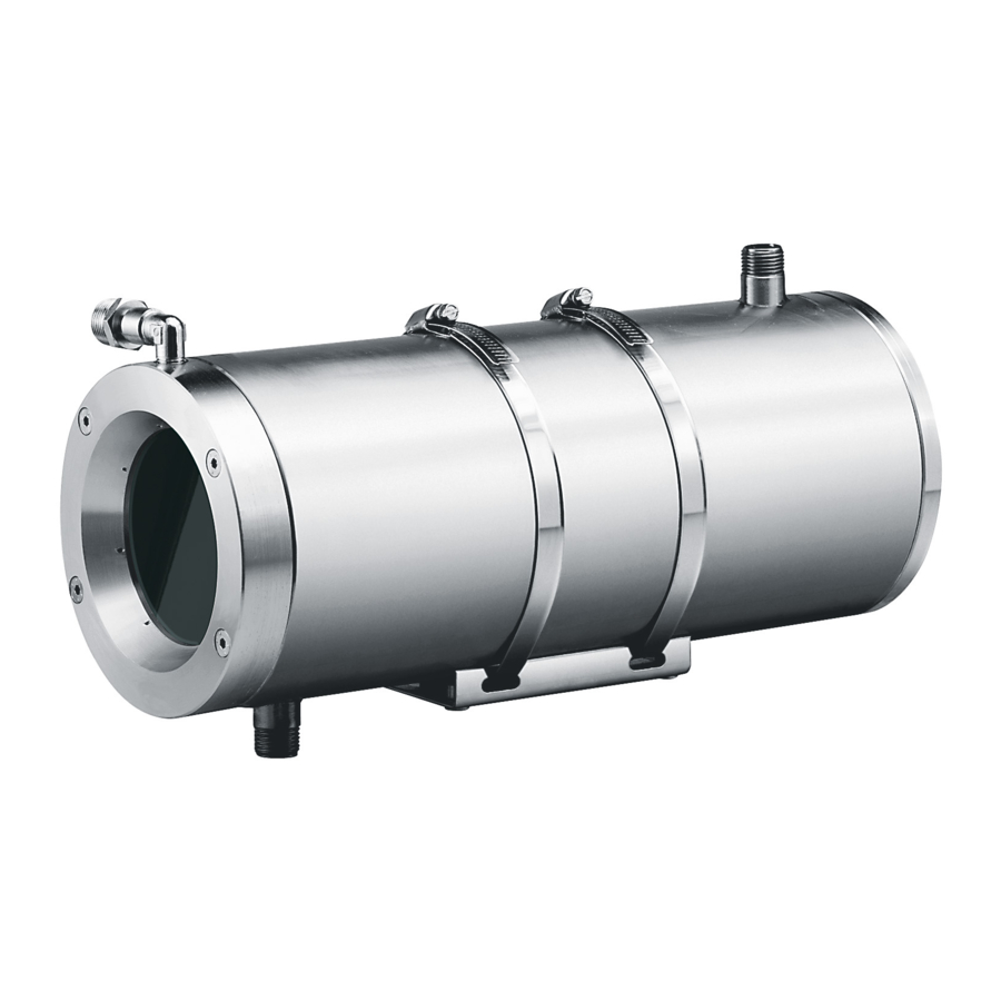
    élevées pourraent nuire au bon fonctionnement d’une caméra. Lors de la livraison du produit, vérifier que Le caisson NTW, construit en acier Inox brillanté est l’emballage est en bon état et l’absence de tout signe composé d’un double corps permettant la circulation évident de chute ou d’abrasion.
  • Page 27: Assemblage Et Installation

    6  Assemblage et  6.1.2 Installation de la caméra Cette section décrit comment installer la caméra à installation l'intérieur du caisson. Ouvrir le caisson comme indiqué précédemment (Fig. L’assemblage et l’installation doivent 01, page 5). exclusivement être effectués par un Fixer la caméra sur la glissière interne au moyen de personnel spécialisé.
  • Page 28: Circuit De Refroidissement

    6.1.3 Circuit de refroidissement 6.1.4 Circuit bride avant barrière d'air Cette section indique comment connecter le Cette section indique de quelle façon connecter la caisson au circuit de l'eau de refroidissement, et bride avant barrière d'air du caisson. La bride barrière fournit les données expérimentales nécessaires d'air est équipée d'un raccord fileté...
  • Page 29: Installation Du Kit Alimentation Pour Caméra

    6.1.5 Installation du kit alimentation pour caméra sp 1mm Cette section décrit comment installer le kit d'alimentation caméra à l'intérieur du caisson. sp 2mm Différents types d'alimentations peuvent être installés. La tension d'entrée peut être de 230Vac ou de 115Vac, tandis que la tension de sortie peut être de 12Vdc ou de 24Vac, 400mA.
  • Page 30: Données Techniques

    9  Données techniques Vitre Saphir 6mm d’épaisseur 9.1 Généralités Température d’utilisation 400°C Trasparence de 0.75 à 4.5 μm Réalisé en acier inox électropoli (alliage austénitique Refroidissement par eau inoxydable résistant à la corrosion et à la chaleur) Exemple d’application avec de l’eau à 20°C: - UNI 6900-71: X 2 Cr Ni Mo 17 12 - Température ambiante 200°C, débit d’eau 2 l/min, - AISI: 316...
  • Page 31: Dessins Techniques

    10  Dessins techniques Les valeurs sont entendues en millimètres. 1/2" GAS Ø 60 1/2" GAS Fig. 9...
  • Page 32 VIDEOTEC S.p.A. www.videotec.com Printed in Italy MNVCNTW_0930_FR...
  • Page 33 Wassergekühltes Gehäuse für Wärmebildkameras Deutsch - Bedienungslanleitung...
  • Page 34 Inhaltsverzeichnis DEuTSCH 1 Allgemeines ........................3 1.1 Schreibweisen ................................. 3 2 Anmerkungen zum Copyright und Informationen zu den Handelsmarken .... 3 3 Sichereitsnormen ......................3 4 Identifizierung ......................4 4.1 Beschreibung und Bezeichnung des Produktes ..................4 4.2 Kennzeichnung des Produkts ..........................4 5 Vorbereitung des Produktes auf den Gebrauch ............
  • Page 35: Allgemeines

    1  Allgemeines 3  Sichereitsnormen Lesen Sie bitte vor dem Installieren und dem Der Hersteller lehnt jede Haftung für Verwenden dieses Gerätes die Bedienungsanleitung eventuelle Schäden ab, die aufgrund sorgfältig durch. Bewahren Sie sie zum späteren unsachgemäßer Anwendung der in diesem Nachschlagen auf.
  • Page 36: Identifizierung

    5.1 Inhalt und Entfernen der Das vollständig aus elektro-poliertem rostfreiem Verpackung Stahl gefertigte Gehäuse NTW besteht aus einem Korpus mit Doppelkammer, in der die Kühlflüssigkeit Bei der Lieferung des Produktes ist zu prüfen, ob die oder die Luft umläuft. Eingefaßt wird der Korpus von...
  • Page 37: Zusammenbau Und Installation

    6  Zusammenbau Und  6.1.2 Einbau der Kamera Dieser Abschnitt behandelt den Einbau der Kamera Installation ins Gehäuseinnere. Das Gehäuse öffnen, wie vorstehend beschrieben Zusammenbau und Installation sind (Fig. 01, Seite 5). Fachleuten vorbehalten. Kamera mit der Schraube 1/4”W unter Benutzung der Isolierbuchse am Innenschlitten befestigen. Bei In der Konfiguration mit einer Bedarf können die beiliegenden Abstandhalter und Versorgungsspannung von 230Vac muß...
  • Page 38: Kühlkreislauf

    6.1.3 Kühlkreislauf 6.1.4 Kreislauf vorderer Luftschrankenflansch Dieser Abschnitt beschreibt, wie das Gehäuse an den Kühlwasserkreislauf angeschlossen wird. Außerdem In diesem Abschnitt wird beschrieben, wie der werden Erfahrungswerte zur Dimensionierung des vordere Flansch als Luftschranke des Gehäuses Kreislaufes genannt. Das Gehäuse ist mit je einem angeschlossen wird.
  • Page 39: Einbau Des Kits Kamera-Netzteil

    6.1.5 Einbau des Kits Kamera-Netzteil Dieser Abschnitt behandelt die Installation sp 1mm des Stromspeisungs-Kits für die Kamera im Gehäuseinnern. Es können mehrere Typen sp 2mm von Netzteilen installiert werden: Mit einer Eingangsspannung von 230Vac oder 115Vac, sowie einer Ausgangsspannung von 12Vdc oder 24Vac, 400mA.
  • Page 40: Technische Daten

    9  Technische Daten Saphir Scheibe Stärke 6mm 9.1 Allgemeines Umgebungstemperatur 400°C Durchlässigkeit von 0.75 bis zu 4.5 μm Aus elektro-poliertem rostfreiem Stahl hergestelltes Wasserkühlung Gehäuse mit Doppelkammer (Legierter Austenitstahl, der rostfrei, korrosions- und hitzebeständig ist) Anwendungsbeispiel mit Eingangswasser mit Temperatur von 20°C: - UNI 6900-71: X 2 Cr Ni Mo 17 12 - Umgebungstemp.
  • Page 41: Technische Zeichnungen

    10  Technische Zeichnungen Maßangabe in Millimeter. 1/2" GAS Ø 60 1/2" GAS Fig. 9...
  • Page 42 VIDEOTEC S.p.A. www.videotec.com Printed in Italy MNVCNTW_0930_DE...
  • Page 44 VIDEOTEC S.p.A. www.videotec.com Printed in Italy MNVCNTW_0930...

Table des Matières