Table des Matières
Publicité
Les langues disponibles
Les langues disponibles
Liens rapides
INSTALLER: PLEASE FAMILIARIZE YOURSELF WITH THIS MANUAL BEFORE PROCEEDING WITH THE
INSTALLATION. LEAVE THIS MANUAL WITH THE APPLIANCE FOR FUTURE REFERENCE.
CONSUMER: RETAIN THIS MANUAL FOR FUTURE REFERENCE.
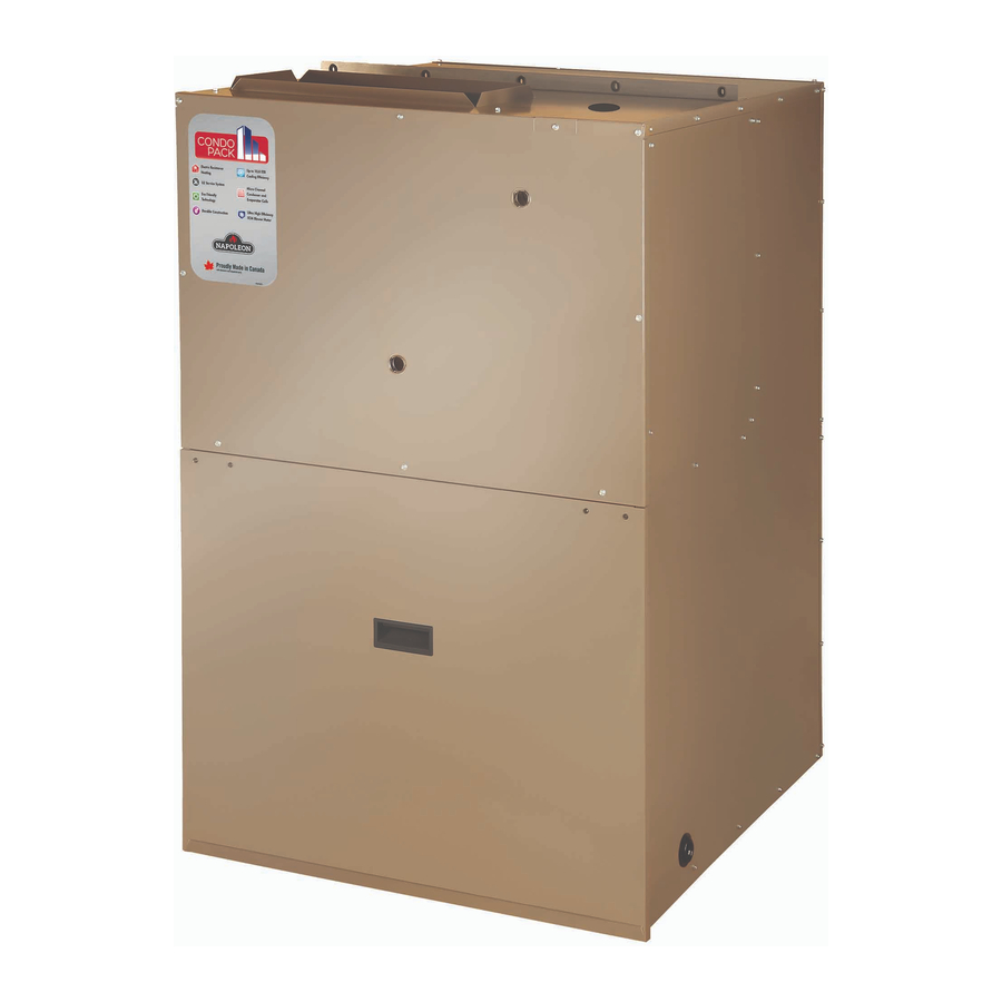
THRU-THE-WALL PACKAGED UNIT
CONFORMS TO ANSI/UL STD. 1995,
CERTIFIED TO CAN/CSA STD. C22.2 NO. 236 AND
ANSI/AHRI STD. 390
9700539
WARNING
!
ELECTRICAL SHOCK, FIRE OR EXPLOSION
HAZARD
FAILURE TO FOLLOW SAFETY WARNINGS
AND INSTRUCTIONS EXACTLY COULD
RESULT IN SERIOUS INJURY, DEATH OR
PROPERTY DAMAGE.
INSTALLATION AND SERVICE MUST BE
PERFORMED BY A QUALIFIED INSTALLER.
IMPROPER INSTALLATION, ADJUSTMENT,
ALTERATION, SERVICE, OR MAINTENANCE
CAN CAUSE INJURY OR PROPERTY
DAMAGE. REFER TO THIS MANUAL AND
CONSULT A SERVICE AGENCY FOR AD-
DITIONAL INFORMATION.
UNIT CONTAINS R-410A REFRIGERANT AND
POE COMPRESSOR OIL.
USE ONLY R-410A REFRIGERANT AND
APPROVED POE COMPRESSOR OIL.
PROPER SERVICE EQUIPMENT IS
REQUIRED. USE ONLY R-410A APPROVED
SERVICE EQUIPMENT.
FOR YOUR SAFETY, DO NOT STORE OR
USE GASOLINE OR OTHER FLAMMABLE
VAPORS AND LIQUIDS IN THE VICINITY OF
THIS OR ANY OTHER APPLIANCE. SUCH
ACTIONS COULD RESULT IN PROPERTY
DAMAGE, PERSONAL INJURY, OR DEATH.
CAUTION
!
INSTALLATION SHALL BE MADE IN ACCOR-
DANCE WITH THE REQUIREMENTS OF THE
LOCAL UTILITY AND OTHER AUTHORITIES
HAVING JURISDICTION, THE NATIONAL
ELECTRICAL CODE IN THE UNITED STATES
AND THE CANADIAN ELECTRICAL CODE
CSA C22.1 PART 1 (LATEST EDITION) IN
CANADA. ANY ALTERATION OF INTERNAL
WIRING WILL VOID CERTIFICATION AND
WARRANTIES.
INSTALLATION AND OPERATING
WITH ELECTRIC HEATING & COOLING
!
THE HIGH EFFICIENCY THRU-THE-WALL
SELF CONTAINED HEATING & COOLING UNIT
• 11 EER
• Up to 24000 BTU/h Cooling
• Up to 15kW Electric Resistance Heating
• R-410A Refrigerant System
• Micro-Channel Condenser and Evaporator Coils
• Removable heating module
• Pre-wired and pre-charged
• Plug-and-play installation and service
• Individual metering and control for each unit
• Installation and service must be performed by a qualifi ed
installer or service agency.
• Before servicing, disconnect all electrical power to the unit.
!
• When servicing controls, label all wires prior to
disconnecting. Reconnect wires correctly.
• Verify proper operation after servicing.
• Do not store or use gasoline or other fl ammable vapors
and liquids in the vicinity of this or any other appliance.
MANUFACTURER RESERVES THE RIGHT TO DISCONTINUE, OR CHANGE AT ANY TIME,
SPECIFICATIONS OR DESIGNS WITHOUT NOTICE AND WITHOUT INCURRING OBLIGATIONS.
Wolf Steel Ltd., 24 Napoleon Rd., Barrie, ON, L4M 0G8 Canada /
103 Miller Drive, Crittenden, Kentucky, USA, 41030
• Phone (866) 820-8686 • hvac@napoleon.com •
INSTRUCTIONS
P-E SERIES
IMPORTANT
!
• www.napoleon.com •
IOM
11 EER
2.0 ton
!
W415-2288 / 08.29.2019
Publicité
Chapitres
Table des Matières
Dépannage

Sommaire des Matières pour Napoleon P-E Série
- Page 1 SPECIFICATIONS OR DESIGNS WITHOUT NOTICE AND WITHOUT INCURRING OBLIGATIONS. CSA C22.1 PART 1 (LATEST EDITION) IN Wolf Steel Ltd., 24 Napoleon Rd., Barrie, ON, L4M 0G8 Canada / CANADA. ANY ALTERATION OF INTERNAL 103 Miller Drive, Crittenden, Kentucky, USA, 41030 WIRING WILL VOID CERTIFICATION AND •...
-
Page 2: Table Des Matières
TABLE OF CONTENTS 1. MODEL NOMENCLATURE ............................ 3 2. OVERVIEW ................................3 3. SAFETY .................................. 4 SAFETY SYMBOLS AND WARNINGS ............................4 .......................... 6 SAFETY RULES CODES ......................................6 4. INSTALLATION ............................... 7 UNIT DIMENSIONS ..................................8 UNIT LOCATION AND CLEARANCES ............................ -
Page 3: Model Nomenclature
1. MODEL NOMENCLATURE HEATING HEATING HEATING COOLING COOLING COOLING CABINET BRAND REVISION TYPE CAPACITY REVISION TYPE CAPACITY REVISION A, B, C... A, B, C... A, B, C... P = Condo Pack NC - No Cool 012 - 12 000 BTU/h / 1.0 ton 018 - 18 000 BTU/h / 1.5 ton C - Gas Condensing 024 - 24 000 BTU/h / 2.0 ton... -
Page 4: Safety
3. SAFETY Only trained service technicians familiar with standard service instructions and training material shall install, service, and repair these units. Improper installation, adjustment, alteration, service, maintenance, or use can cause explosion, fire, electrical shock, or other conditions which may cause death, personal injury, or property damage. -
Page 5: Important
IMPORTANT A DIRTY, CLOGGED AIR FILTER MUST BE CLEANED OR REPLACED. IF NOT CLEANED OR REPLACED PROMPTLY, THE AUTO-RESET HIGH TEMPERATURE LIMIT SWITCH WILL CYCLE THE HEATING ELEMENTS ON AND OFF, WHICH COULD REDUCE THE LONGEVITY OF THE HEATING ELEMENTS AND REDUCE THE SYSTEM PERFORMANCE. A SEVERELY CLOGGED FILTER, INLET OR OUTLET DUCT COULD CAUSE FAILURE OF THE NON-RESETTABLE HIGH TEMPERATURE LIMIT SWITCH, AT WHICH POINT A QUALIFIED SERVICE TECHNICIAN MUST BE CONTACTED TO PERFORM NECESSARY SERVICE. -
Page 6: Safety Rules
SAFETY RULES 1. For starting up and shutting down the unit refer to “6. STARTUP AND SHUTDOWN”. 2. Store this unit only in dry indoor locations (protected from weather and extreme cold temperatures). 3. DO NOT install this unit outdoors or in a mobile home, trailer or recreational vehicle. This appliance is not designed/ certified for these installations. -
Page 7: Installation
4. INSTALLATION WALL SLEEVE The unit is shipped in one package, completely assembled CABINET and wired. The air conditioning condensate drain is shipped separately with SUPPLY OUTLET the unit for field install. ELECTRICAL SLOT If any damage is found, proper notation should be made on the carrier’s freight bill. -
Page 8: Unit Dimensions
UNIT DIMENSIONS 16" 16 " 2 " 8 " 8 " 8" SUPPLY OUTLET ELECTRICAL CONNECTION 28" 5 " 29" Control Board Inspection Window 8 " 8 " MIN DRAIN FLOOR 16 " 16 " " 8 " 16 " 4 "... -
Page 9: Unit Location And Clearances
UNIT LOCATION AND CLEARANCES NOTE OUTSIDE ALTHOUGH IT IS NOT POSSIBLE TO DETAIL ALL OF Sleeve Flange CONSTRUCTION PARAMETERS THAT COULD BE ENCOUNTERED, THE FOLLOWING GUIDELINES AND PRECAUTIONS ARE RECOMMENDED: Drain holes • MASONRY WALLS MUST HAVE A LINTEL TO SUPPORT THE WALL. - Page 10 WARNING THIS UNIT IS CERTIFIED FOR INSTALLATION ON COMBUSTIBLE FLOORS. THIS SHALL BE INTERPRETED AS A WOOD FLOOR ONLY. THE UNIT MUST NOT BE INSTALLED DIRECTLY ON CARPETING, OR OTHER COMBUSTIBLE MATERIAL EXCEPT WOOD. INSTALLATION ON COMBUSTIBLE MATERIAL OTHER THAN WOOD CAN RESULT IN FIRE, CAUSING PROPERTY DAMAGE, PERSONAL INJURY OR DEATH.
-
Page 11: Minimum Clearances
4.2.1 Minimum Clearances The minimum clearances required for installation and accessibility are shown below. These clearances should be followed unless otherwise approved by the manufacturer. FIG. 4.2.1.A W415-2288 / 08.29.2019... - Page 12 FIG. 4.2.1.B W415-2288 / 08.29.2019...
-
Page 13: Packaged Unit Preparation
PACKAGED UNIT PREPARATION NOTE • THIS UNIT MUST BE INSTALLED IN ACCORDANCE WITH ALL APPLICABLE CODES. • THIS UNIT IS APPROVED FOR THRU-THE-WALL INSTALLATION ONLY. • THESE INSTALLATION AND MAINTENANCE INSTRUCTIONS SHOULD BE LEFT WITH THE UNIT FOR FUTURE REFERENCE. Prior to installing the unit in the wall opening: 1. -
Page 14: Wall Sleeve Assembly And Installation
WALL SLEEVE ASSEMBLY AND INSTALLATION WARNING THESE INSTRUCTIONS ARE INTENDED AS AN AID TO QUALIFIED SERVICE PERSONNEL FOR PROPER INSTALLATION, ADJUSTMENT AND OPERATION OF THE UNIT. READ THESE INSTRUCTIONS THOROUGHLY BEFORE ATTEMPTING INSTALLATION OR OPERATION. IMPROPER INSTALLATION, ADJUSTMENT, SERVICE, OR MAINTENANCE CAN CAUSE PROPERTY DAMAGE, PERSONAL INJURY, OR DEATH. CONSULT A QUALIFIED INSTALLER OR SERVICE AGENCY FOR INFORMATION AND ASSISTANCE. - Page 15 Wall Sleeve Dimensions DIAGRAM (B) TWO DIFFERENT WALL SLEEVE MODELS ARE DEPICTED BELOW: • CWSMUA • CWSMUA19 NOTE: TO IMPROVE RIGIDITY AND REDUCTION IN VIBRATION WALL MOUNTING BRACKETS CAN BE USED TO AFFIX WALL SLEEVE TO BUILDING SUB STRUCTURE FROM INSIDE OR OUTSIDE OF THE BUILDING. ENGINEER/ARCHITECT TO CONSULT WITH CUSTOMER SOLUTIONS IF CLARIFICATION IS REQUIRED TO DETERMINE BRACKET LOCATION FOR SETTING THE DESIRED DEPTH...
- Page 16 4.4.1 Wall Sleeve Assembly Place Base part (2) on the fl oor and attach Right Side Panel (3): a. Position Base Panel (2) to seat behind fl anges on the Side Panel (3). b. Bring together panel clips and the openings (FIG.
- Page 17 Check for parallel position of Left and Right Side Panels (3) and (4). Secure connection with Base Panel (2), see (FIG. 4). Attach Top Panel (1) to Left and Right Side Panels (3) and (4). Align connection openings and secure the assembly by pushing the clips in place (FIG.
- Page 18 4.4.2 Wall Sleeve Installation WARNING INSTALLATION CREW MUST ADHERE TO ALL LOCAL/NATIONAL SAFE WORK PRACTICES INCLUDING EMPLOYING APPROPRIATE FALL ARREST EQUIPMENT When installed, the Wall Sleeve must protrude Finished Wall 1/2” MIN. to 1” MAX. beyond the exterior fi nished wall Flashing PROTRUDE to allow proper water evacuation through the drain holes...
- Page 19 NOTE: The following support bracket locations are for installations where the wall sleeve is installed from the OUTSIDE of the building. For installations where the wall sleeve is installed from the INSIDE of the building, the Side Support Brackets (5) need to be mounted on INTERIOR wall, so they will need to be relocated on the wall sleeve (new screw positions may need to be created depending of the type of wall construction).
- Page 20 To install Wall Sleeve into the wall opening: With drain holes facing outside, position the sleeve towards the wall until the support brackets are set on wall edge. Leave ¼ “ space in between the wall and the wall sleeve a.
-
Page 21: Unit Support
UNIT SUPPORT The wall sleeve is not intended as the sole support for DO NOT OPERATE THE FURNACE FOR PROLONGED CAUTION the unit. Therefore, additional support must be provided PERIODS OF TIME WITHOUT AN AIR FILTER. A ALWAYS by a rigid structure that bears the weight of the unit and WEAR SAFETY GLASSES WHEN WORKING WITH provides an interface for “return air”... -
Page 22: Gasketing On Wall Sleeve
c. An additional vibration isolation material (must be non-combustible) may be used if required. d. Ensure that the platform connection to Condo Pack Return Air Opening is at least 24 1/8” x 8 1/4”. It must be aligned with return air opening on the base of the installed Condo Pack appliance. e. -
Page 23: Packaged Unit Installation
PACKAGED UNIT INSTALLATION Procedure 1. Verify that isolation grommets are installed in the five holes on the top mounting bracket. 2. Bring the Condo Pack as close as possible to wall opening (FIG. 4.6.A). Carefully slide the unit into the Wall Sleeve (refer to “4.4 Wall Sleeve Assembly and Installation”) so the front of the unit is in contact with the front flanges of the Wall Sleeve. - Page 24 4.7.1 SEALING: Wall Sleeve and Condo Pack Cabinet Fill the clearance space between the sleeve and the cabinet with non-hardening caulking compound or non-expanding insulation foam as a protection against the snow, water, SEAL moisture and air infi ltration. CORNERS IMPORTANT THE CLEARANCE SPACE BETWEEN THE WALL Wall...
-
Page 25: Ductwork
DUCTWORK 4.8.1 Supply Air Ducting IMPORTANT BOTH SUPPLY AND RETURN AIR MUST BE DUCTED TO THE APPLIANCE FROM ROOMS SEPARATE TO THE CLOSET ENCLOSURE HOUSING THE APPLIANCE. SUPPLY AIR DUCT (PLENUM) CONNECTION MUST BE AT LEAST THE SAME SIZE AS THE UNIT SUPPLY AIR OPENING. - Page 26 4.8.2 Return Air Ducting Provide the support inside the building in the area of the return air opening. The support should be high enough to allow for return air to the unit as per requirements. If required, install a resilient material between the support and the base of the unit to reduce the possible transmission of sound and vibration.
-
Page 27: Condensate Drain Connection
CONDENSATE DRAIN CONNECTION A properly functioning condensate trap provides discharge of water from the cooling coil drain pan, while the water seal (the water level maintained in the trap) prevents the fl ow of ambient air in or out of the unit. The pre-fabricated condensate drain connection hose (with integral P trap) for air conditioning section is included but not installed. -
Page 28: Electrical
5. ELECTRICAL WARNING ALL ELECTRICAL WORK MUST BE DONE BY A TRAINED, QUALIFIED TECHNICIAN. IMPROPER MODIFICATIONS OR ADJUSTMENTS CAN RESULT IN FIRE OR EXPLOSION, CAUSING PROPERTY DAMAGE, SEVERE PERSONAL INJURY OR LOSS OF LIFE. • In Canada, all electrical work and grounding must be in accordance with the latest edition of CSA-C22.1, Canadian Electrical Code Part 1, and any applicable local code. -
Page 29: Power Supply Installation
5.1.3 Power Supply Installation Reducing Cover Plate ELECTRICAL Large SUPPLY SLOT SUPPLY OUTLET HEATING Medium MODULE SIDE FRONT PANEL ACCESS PANEL Electrical Slot COOLING SECTION Small Locate the Position the cover reducing plate Reducing Cover Plates: electrical supply slot over the electrical slot and secure Based on cable gauge, determine the on the top of cabinet enclosure. -
Page 30: Electrical Panel
5.1.4 Electrical Panel Power Cable BLACK THERMOSTAT BLACK Heater BLACK Ground Panel Connection BLACK GREEN BLACK Transformer POWER DISTRIBUTION BLOCKS Breaker Breaker Relay Relay BLACK BLACK BLACK WHITE Relay Low Voltage FUSE HOLDERS Fuse 2.5 A G W C Y/Y2 Terminal Block BLACK BLACK... -
Page 31: Wiring Diagrams
5.1.5 Wiring Diagrams 5.1.5.1 Heating Module Wiring Diagram W415-2288 / 08.29.2019... -
Page 32: Air Conditioning Section - Wiring Diagram / Schéma De Câblage
5.1.5.2 Air Conditioner Section Wiring Diagram AIR CONDITIONING SECTION - WIRING DIAGRAM / SCHÉMA DE CÂBLAGE UPPER MODULE AIR CONDITIONING SECTION SEE CONTINUING DETAIL ON UPPER MODULE WIRING DIAGRAM / VOIR LES DÉTAILS SUR LE SCHÉMA DE CÂBLAGE DU MODULE SUPÉRIEUR ECM X-13 MOLEX MOTOR SEE NOTE 1... -
Page 33: Wiring Diagram / Schéma De Câblage
5.1.5.3 Blower Only (Lower Module) Wiring Diagram WIRING DIAGRAM / SCHÉMA DE CÂBLAGE SEE CONTINUING DETAIL ON UPPER MODULE WIRING DIAGRAM / VOIR LES DÉTAILS SUR LE SCHÉMA DE CÂBLAGE DU MODULE SUPÉRIEUR ECM X-13 MOLEX MOTOR SEE NOTE 1 CONNECTIONS 24V CONTROL SIGNAL TO... -
Page 34: Removal Of Heating Module, Condenser Fan And Indoor Blower
REMOVAL OF HEATING MODULE, CONDENSER FAN AND INDOOR BLOWER NOTE: The number of breakers and relays on the control panel will vary depending on the heating capacity of the unit. “5.2.4 Electrical and Refer to Physical Data” HEATING MODULE NOTE: VESTIBULE If harness needs to be VESTIBULE... -
Page 35: Risk Of Electrical Shock
5.2.1 Heating Module Removal WARNING RISK OF ELECTRICAL SHOCK ! DISCONNECT POWER BEFORE INSTALLATION. Power Cables Disconnect power to unit. Remove power Remove the screws from the furnace cables. Pull down and remove the front panel. front panel. ground cable Squeeze the Squeeze the two tabs on the X13 two tabs on the... - Page 36 Transformer Distribution Block Do not forget to remove the side screw #9. Fuse Block Side Screw Remove all 9 screws holding the heating module in, as shown in the this diagram (28). When sliding heating module back into the cabinet, make sure the module Transformer slides UNDER...
- Page 37 5.2.2 Condenser Fan Removal To remove condenser fan, heating module must be removed first. Refer to steps 1-16 shown in “Heating Remove two screws holding Module Removal”. Remove side manifold cover baffle. side manifold cover baffle. Remove rear manifold cover baffle. Remove 4 rear manifold screws (one from the top).
- Page 38 Thread the wiring back through Using four bolts, four washers Slide in condenser fan assembly. the hole of the module. and four locknuts, install fan back. Mount condenser fan shroud by installing 10 screws (3 on the top and 7 at the bottom). Make sure that insulation peace is not damaged.
- Page 39 5.2.3 Blower Removal Remove heating module. Refer to steps 1-16 from ”Heating Module Removal” section. Remove seven screws along the back. Remove 10 round head and 6 hex head screws. Remove top blower plate. Remove 10 screws from the front blower plate and electrical plate Remove Molex connector from the (with capacitor and contactor on it).
- Page 40 Install 10 screws to the front blower plate and electrical plate (with capacitor and contactor on it). Electrical plate Install electrical plate (with Lift and place blower down into cabinet. capacitor and contactor attached). Connect Molex connector to the Place top blower plate back into place.. front blower plate.
- Page 41 5.2.4 Electrical and Physical Data TABLE 4. * Models with A18A & A24A Air Conditioning have two speed condenser fan motor. Speed 1 is for A18A and Speed 2 is for A24A units. W415-2288 / 08.29.2019...
- Page 42 5.2.5 Low Voltage Wiring The thermostat and control wiring should be a minimum of 18 AWG copper. Excessive lengths of wire may result in enough voltage drop to impair the proper functioning of the furnace. For thermostat wires in excess of 25 feet (7.6m), use 16 AWG;...
-
Page 43: Startup And Shutdown
6. STARTUP AND SHUTDOWN The Condo Pack is designed to be used with residential single-stage cooling and single-stage heating wall thermostats with automatic or manual mode changeover. Automatic changeover thermostats must include a dead-band to prevent cycling between cooling and heating modes. Single-pole, single-throw thermostats are not suitable for use with Condo Pack. -
Page 44: Sequences Of Operation
SEQUENCES OF OPERATION 6.2.1 Heating Cycle 1. When thermostat switch is set to heat, the terminals R&W get connected which will energize the indoor blower and all the relays for the heating elements immediately. 2. Relay 1, once energized, turns the first Heating element ON with up to 1 second delay. At the same time Relay 2 powers the rest of the heating elements with delay range from 1 to 8 seconds (applicable to 7.5 kW, 10kW, and 15 kW). -
Page 45: Air Flow
AIR FLOW For proper heating operation, air fl ow over the heating elements is of utmost importance. Insuffi cient airfl ow accelerates metal fatigue and possible failure in the heat elements, as well as increases the possibility of the furnace being shut down by the high temparature limit switches. IMPORTANT DO NOT BYPASS THIS STEP OF THE START UP PROCEDURES. - Page 46 6.3.4 Factory Set Motor Speeds and available CFM Available Motor Speed Taps Heating Module / Speed Heating Module / Speed TABLE 6. Model No. Setting Model No. Setting Cooling Tap# Cooling Tap# P-E 2.0 ton FACTORY FACTORY E05A E07A CFM at External Static Pressure (inches of Water Column) P-E05A-A12A-A FACTORY P-E07A-A12A-A...
-
Page 47: Maintenance
7. MAINTENANCE GENERAL SAFETY RULES WARNING DISCONNECT THE ELECTRICAL POWER SUPPLY TO THE UNIT BEFORE ATTEMPTING ANY MAINTENANCE. FAILURE TO DO SO CAN CAUSE ELECTRICAL SHOCK RESULTING IN PERSONAL INJURY OR LOSS OF LIFE. THE ELECTRICAL CONNECTION AND SUBSEQUENT SERVICE MUST BE DONE BY A QUALIFIED ELECTRICIAN IN ACCORDANCE WITH THIS MANUAL AND ELECTRICAL CODES HAVING JURISDICTION IN YOUR AREA. -
Page 48: Heating Module
HEATING MODULE Follow these procedures before inspecting heating module. • Turn room thermostat to its lowest or off setting. • Wait at least five minutes for heating module to cool if it was recently operating. • Turn off unit electrical power; failure to do so could result in injury or death. IMPORTANT USE ONLY RECOMMENDED REPLACEMENT PARTS. -
Page 49: Lubrication
DO NOT OPERATE THIS EQUIPMENT WITHOUT AN AIR FILTER. A portion of the dust entrained in the air may temporarily lodge in the air duct runs and the supply registers. Any recirculated dust particles will be heated and charred by coming into contact with the heat exchanger. This residue will soil ceilings, walls, drapes, carpets, furniture, and other household articles. -
Page 50: Troubleshooting
8. TROUBLESHOOTING AIR CONDITIONING TROUBLESHOOTING TABLE 8. AIR CONDITIONING TROUBLESHOOTING GUIDE THIS TROUBLESHOOTING GUIDE IS INTENDED FOR USE BY WARNING! QUALIFIED SERVICE PERSONNEL ONLY! FAULT CONDITION POSSIBLE CAUSE CORRECTION Power disconnected or loose Check power supply to unit connection Check voltage at contactor in condensing unit Blown fuse / breaker tripped Replace fuses/reset breaker. - Page 51 TABLE 8. CONT. AIR CONDITIONING TROUBLESHOOTING GUIDE THIS TROUBLESHOOTING GUIDE IS INTENDED FOR USE BY WARNING! QUALIFIED SERVICE PERSONNEL ONLY! FAULT CONDITION POSSIBLE CAUSE CORRECTION At compressor terminals, voltage must be Incorrect voltage +/10% of nameplate marking when unit is Compressor Operates in operating short cycles...
-
Page 52: Adjusting System Charge
ADJUSTING SYSTEM CHARGE Units come from the factory charged with the correct amount of refrigerant. There are times, however, when the charge may need to be adjusted. Refrigerant leaks and addition of system components for servicing or monitoring, for example, will require that the refrigerant charge be adjusted for the unit to function as intended. Note that only qualified HVAC technicians shall adjust the charge. -
Page 53: Heating Module Troubleshooting
HEATING MODULE TROUBLESHOOTING TABLE 10. HEATER MODULE TROUBLESHOOTING GUIDE THIS TROUBLESHOOTING GUIDE IS INTENDED FOR USE BY WARNING! QUALIFIED SERVICE PERSONNEL ONLY! FAULT CONDITION POSSIBLE CAUSE CORRECTION Connect power and/or turn the power disconnect Power disconnected or Loose switch ON. Make sure all the wiring connections are wiring connections Unit will not operate. -
Page 54: P-E Condo Pack Replacement Parts List
9. P-E CONDO PACK REPLACEMENT PARTS LIST Contact your dealer or the factory for questions concerning prices and policies on replacement parts. Normally all parts can be ordered through your Authorized dealer / distributor. WARNING FOR WARRANTY REPLACEMENT PARTS, A PHOTOCOPY OF THE ORIGINAL INVOICE WILL BE REQUIRED TO HONOUR THE CLAIM. - Page 55 TABLE 11. P-E CABINET, FAN AND BLOWER ASSEMBLY PARTS LIST: ITEM NO. PART NUMBER DESCRIPTION W062-0041 BLOWER, 10-6T HOUSING (GF) W010-4537 ASSY, PROGRAMMED X13 1/3HP MOTOR (A24A) W080-1925 BRACKET, BLOWER MOUNT LS (A24A) W080-1926 BRACKET, BLOWER MOUNT RS (A24A) W080-1924 BRACKET, BLOWER MOUNT BACK (A24A) W361-0345 INSULATION,DUCTLINER 2.625"X21.25"...
-
Page 56: Cooling Section Parts List
COOLING SECTION PARTS LIST NOTE For field replacement of the COREMAX CORE (#28, W450-0236 - not supplied with the unit) the following tool (SCFT20A) from Fastest Inc. needs to be used which also reduces the refrigerant loss during the process. Please note that the COREMAX CORE valve is not a standard schrader valve. - Page 57 COOLING SECTION PARTS LIST: TABLE 12. ITEM NO. PART NUMBER DESCRIPTION HX MC, FLAT COND 940.2MM X 661MM (CP) W770-0015 INSULATION,FRONT PANEL SEAL 1/8" FFM W290-0315 FILTER, 16"X25"X1" HH (ACHP) W250-0012 HX MC, EVAPORATOR 403.3MMX676.8MM (CP) W770-0014 COREMAX CORE NUT (1/2-20 X 7/16--20) W450-0236 1/2-20 HEX JAM NUT (BRASS) W450-0237...
-
Page 58: P-E Heating Module
P-E HEATING MODULE W415-2288 / 08.29.2019... - Page 59 P-E HEATING MODULE PARTS LIST: TABLE 13. ITEM NO. PART NUMBER DESCRIPTION W010-3584^ ASSY, ELECTRIC HEATER PANEL 15kW W010-3538^ ASSY, ELECTRIC HEATER PANEL 10kW W010-3583^ ASSY, ELECTRIC HEATER PANEL 7.5kW W010-3582^ ASSY, ELECTRIC HEATER PANEL 5kW W660-0184 TEMPERATURE CUT-OUT AUTO RESET °C W660-0185 FUSIBLE LINK 170.6F (77...
-
Page 60: Owner's Service Information
10. OWNER’S SERVICE INFORMATION TABLE 14. HOMEOWNER’S REFERENCE TABLE Model No. (Model number located in the right corner of the upper front door) Serial No. (Serial number located in the right corner of the upper front door) Date Installed Contractor Contact Address Postal Code/Zip Code... -
Page 61: Warranty
For further information about this warranty, contact Wolf Steel Ltd. Customer Solutions by phone: 1-866-820-8686 • • by email: hvac@napoleon.com • or mail to: Wolf Steel Ltd., 24 Napoleon Road, Barrie, Ontario L4M 0G8 Canada. w w w . n a p o l e o n . c o m H2.6 07.24.19... - Page 62 44.1 W415-2288 / 08.29.2019...
- Page 63 44.1 W415-2288 / 08.29.2019...
- Page 64 NAPOLEON CELEBRATING OVER 40 YEARS OF HOME COMFORT PRODUCTS 7200, Route Transcanadienne, Montréal, Québec H4T 1A3 24 Napoleon Road, Barrie, Ontario, Canada L4M 0G8 214 Bayview Drive, Barrie, Ontario, Canada L4N 4Y8 103 Miller Drive, Crittenden, Kentucky, USA 41030 Phone: 1-866-820-8686 napoleon.com...
- Page 65 LA CONCEPTION EN TOUT TEMPS, SANS PRÉAVIS ET SANS AUTRE OBLIGATION DE SA PART. ÉTATS-UNIS ET DE LA NORME C22.1, PARTIE 1 (DERNIÈRE ÉDITION) DU CODE CANADIEN Wolf Steel ltée, 24, rue Napoleon, Barrie (Ontario) L4M 4Y8 Canada / DE L’ÉLECTRICITÉ. TOUTE MODIFICATION 103, Miller Drive, Crittenden, Kentucky, É.-U., 41030 AU CÂBLAGE INTERNE ANNULERA LA...
- Page 66 TABLE DES MATIÈRES 1. DESCRIPTION DU MODÈLE ............................3 2. VUE D’ENSEMBLE ............................... 3 3. SÉCURITÉ ..................................4 SYMBOLES DE SÉCURITÉ ET AVERTISSEMENTS ......................4 CONSIGNES DE SÉCURITÉ ................................6 CODES ......................................6 4. INSTALLATION ................................7 DIMENSIONS DE L’APPAREIL ..............................
-
Page 67: Description Du Modèle
1. DESCRIPTION DU MODÈLE TYPE DE CAPACITÉ DE RÉVISION DE TYPE DE CAPACITÉ DE RÉVISION DE RÉVISION DU MARQUE CHALEUR CHALEUR CHALEUR REFROIDISSEMENT REFROIDISSEMENT REFROIDISSEMENT CAISSON A, B, C A, B, C P=Condo Pack A, B, C NC - Soufflerie seulement 018 - 18 000 BTU/h / 1, 5 tonne 024 - 24 000 BTU/h / 2, 0 tonnes C - Condensa�on au gaz... -
Page 68: Sécurité
3. SÉCURITÉ Seul un technicien de service formé et qualifié possédant une bonne maîtrise des instructions d’entretien standard et du matériel de formation devrait effectuer le service ainsi que l’installation et la réparation de ces appareils. Une installation non conforme, des réglages, des modifications, un service, un entretien ou un usage inadéquats peuvent provoquer une explosion, un incendie, une électrocution ou d’autres situations pouvant entraîner la mort, des blessures corporelles ou des dommages matériels. - Page 69 AVERTISSEMENT CETTE INFORMATION EST DESTINÉE AUX TECHNICIENS EN CVC QUALIFIÉS. TOUTE TENTATIVE DE RÉPARATION D’UN CLIMATISEUR CENTRAL PEUT ENTRAÎNER DES BLESSURES CORPORELLES OU DES DOMMAGES MATÉRIELS. LE FABRICANT OU LE VENDEUR NE SONT PAS RESPONSABLES DE L’INTERPRÉTATION DE CETTE INFORMATION ET N’ASSUMENT AUCUNE RESPONSABILITÉ LIÉE À SON UTILISATION. ATTENTION •...
-
Page 70: Consignes De Sécurité
CONSIGNES DE SÉCURITÉ 1. Les procédures de mise en marche et d’arrêt de l’appareil sont décrites au point « 6. MISE EN MARCHE ET ARRÊT ». 2. Cet appareil doit être entreposé à l’intérieur, dans un endroit sec (à l’abri des intempéries et des températures extrêmement froides). -
Page 71: Installation
4. INSTALLATION MANCHON L’appareil est livré en un seul MURAL morceau, complètement assemblé et câblé. CABINET Le conduit d’évacuation d’eau de condensation du climatiseur est expédié séparément afin qu’il soit OUVERTURE DE L’ALIMENTATION SORTIE D’AIR ÉLECTRIQUE installé sur place. Si l’appareil neuf présente des dommages, signalez-les sur le bon de livraison du transporteur. -
Page 72: Dimensions De L'appareil
DIMENSIONS DE L’APPAREIL 16 po 16 po 2 po 8 po SORTIE D’AIR 8 po CABLES 28 po ELECTRIQUES 29 po Hublot d’inspection du panneau de commande 8 po CONDUIT DE DRAINAGE 8 po MIN. DU CLIMATISEUR 16 po 8 po 16 po 16 po PLANCHER... -
Page 73: Emplacements Et Dégagements De L'appareil
EMPLACEMENTS ET DÉGAGEMENTS DE L’APPAREIL REMARQUE EXTÉRIEUR Rebord BIEN QU’IL SOIT IMPOSSIBLE DE FOURNIR UNE du manchon DESCRIPTION DÉTAILLÉE DE TOUS LES PARAMÈTRES DE CONSTRUCTION POUVANT EXIS- TER, IL EST RECOMMANDÉ DE TENIR COMPTE DES Trous de drainage DIRECTIVES ET PRÉCAUTIONS SUIVANTES : •... - Page 74 AVERTISSEMENT CET APPAREIL EST HOMOLOGUÉ POUR INSTALLATION SUR UN PLANCHER COMBUSTIBLE. SEUL UN PLANCHER EN BOIS EST CONSIDÉRÉ COMME UNE SURFACE COMBUSTIBLE. L’APPAREIL NE DOIT PAS ÊTRE INSTALLÉ DIRECTEMENT SUR DU TAPIS OU D’AUTRES MATÉRIAUX COMBUSTIBLES, À L’EXCEPTION DU BOIS. L’INSTALLATION SUR UN MATÉRIAU COMBUSTIBLE (AUTRE QUE LE BOIS) PEUT OCCASIONNER UN INCENDIE, CAUSANT AINSI DES DOMMAGES MATÉRIELS, DES BLESSURES CORPORELLES OU LA MORT.
-
Page 75: Dégagements Minimaux
4.2.1 Dégagements minimaux Les dégagements minimaux requis pour l’installation et l’accessibilité sont présentés ci-dessous. Ces dégagements doivent être respectés, à moins d’une dérogation accordée par le fabricant. FIG. 4.2.1. A W415-2288 / 08.29.19... - Page 76 FIG. 4.2.1. B W415-2288 / 08.29.19...
-
Page 77: Préparation De L'unité Multifonction
PRÉPARATION DE L’UNITÉ MULTIFONCTION REMARQUE • CET APPAREIL DOIT ÊTRE INSTALLÉ CONFORMÉMENT À TOUS LES CODES EN VIGUEUR. • CET APPAREIL EST HOMOLOGUÉ POUR L’INSTALLATION DE L’UNITÉ MURALE MULTIFONCTION SEULEMENT. • CES INSTRUCTIONS D’INSTALLATION ET D’ENTRETIEN DEVRAIENT ÊTRE RANGÉES AVEC L’APPAREIL POUR POUVOIR ÊTRE CONSULTÉES ULTÉRIEUREMENT. -
Page 78: Assemblage Et Installation Du Manchon Mural
ASSEMBLAGE ET INSTALLATION DU MANCHON MURAL AVERTISSEMENT CES INSTRUCTIONS SONT DESTINÉES À AIDER LES TECHNICIENS DE SERVICE QUALIFIÉS À INSTALLER, À RÉGLER ET À FAIRE FONCTIONNER ADÉQUATEMENT L’APPAREIL. LISEZ ATTENTIVE- MENT CES DIRECTIVES AVANT DE PROCÉDER À L’INSTALLATION DE L’APPAREIL ET DE LE FAIRE FONCTIONNER. -
Page 79: Dimensions Du Manchon Mural
Dimensions du manchon mural SCHÉMA (B) DEUX MODÈLES DE MANCHONS MURAUX SONT ILLUSTRÉS CI-DESSOUS : • CWSMUA • CWSMUA19 REMARQUE POUR PLUS DE SOLIDITÉ ET POUR RÉDUIRE LES VIBRATIONS DU SUPPORT MURAL, DES SUPPORTS PEUVENT ÊTRE UTILISÉS POUR FIXER LE MANCHON MURAL À LA SOUS STRUCTURE DE L’ÉDIFICE, ET CE, DE L’INTÉRIEUR OU DE L’EXTÉRIEUR DE L’ÉDIFICE. -
Page 80: Assemblage Du Manchon Mural
4.4.1 Assemblage du manchon mural Placez le panneau de base (2) sur le plancher et fi xez le panneau latéral droit (3) : a. Placez le panneau de base (2) de façon à ce qu’il soit appuyé derrière les brides du panneau latéral (3). - Page 81 Assurez-vous que les panneaux latéraux de gauche et de droite (3) et (4) sont parallèles. Vérifi ez qu’ils sont bien fi xés au panneau de base (2), voir la (FIG. 4). Fixez le panneau supérieur (1) aux panneaux latéraux de gauche et de droite (3) et (4).
-
Page 82: Installation Du Manchon Mural
4.4.2 Installation du manchon mural AVERTISSEMENT L’ÉQUIPE D’INSTALLATION DOIT SE CONFORMER À TOUTES LES RECOMMANDATIONS LOCALES ET NATIONALES EN MATIÈRE DE PRATIQUES DE TRAVAIL SÉCURITAIRE, Y COMPRIS L’UTILISATION DE DISPOSITIF ANTICHUTE. Mur fini Une fois installé, le manchon mural doit dépasser le mur fi ni extérieur d’au moins 1/2 po et d’au plus 1 po afi n que l’eau Solin PROTRUDE de... -
Page 83: Support Standard
REMARQUE : Les emplacements des supports suivants servent aux installations de l’appareil lorsque le manchon mural est fi xé à partir de l’EXTÉRIEUR de l’édifi ce. Pour les installations nécessitant la fi xation du manchon mural à l’INTÉRIEUR de l’édifi ce, Les supports latéraux (5) doivent être fi... -
Page 84: Scellage : Manchon Mural Et Construction Du Mur
Installation du manchon mural dans l’ouverture du mur : En gardant les trous de drainage face vers l’extérieur, tirez le manchon vers le mur, jusqu’à ce que les supports soient insérés dans les parois du mur Laissez un espace de ¼ po entre le mur et le manchon mural a n d’y insérer de la mousse isolante à... -
Page 85: Support De L'appareil
SUPPORT DE L’APPAREIL Le manchon mural n’est pas conçu pour être l’unique support de ATTENTION l’appareil. Par conséquent, un soutien supplémentaire doit être assuré par une structure rigide qui supporte le poids de l’appareil PORTEZ TOUJOURS DES LUNETTES DE SÉCURITÉ et fournit une interface pour les conduits de retour d’air. -
Page 86: Application De Joints D'étanchéité Sur Le Manchon Mural
c. Un matériau antivibrations supplémentaire (qui doit être non combustible) peut être utilisé au besoin. d. Veillez à ce que la jonction entre la plateforme et l’ouverture de retour d’air du Condo Pack soit d’au moins 8 1/4 po (21 cm) X 24 1/8 po (61,3 cm). La plateforme doit être alignée avec l’ouverture de retour d’air à la base du Condo Pack. e. -
Page 87: Installation De L'unité Multifonction
INSTALLATION DE L’UNITÉ MULTIFONCTION Procédure 1. Vérifiez que les bagues d’isolement sont installées dans les cinq trous sur le support supérieur. 2. Placez le Condo Pack le plus près possible de l’ouverture du mur (FIG. 4.6.A). Faites glisser délicatement l’appareil dans le manchon mural (consultez les instructions 4.4 ASSEMBLAGE ET INSTALLATION DU MANCHON MURAL) afin que l’avant de l’appareil soit en contact avec les brides avant du manchon mural. - Page 88 4.7.1 SCELLAGE : Manchon mural et cabinet de l’appareil Condo Pack SCELLANT Scellez l’espace entre le manchon mural et le cabinet en DANS LES utilisant un produit de calfeutrage non durcissant ou de COINS la mousse isolante à faible expansion pour empêcher l’infi ltration de neige, d’eau, d’humidité...
-
Page 89: Système De Conduits
SYSTÈME DE CONDUITS 4.8.1 Conduits d’alimentation d’air IMPORTANT L’AIR SOUFFLÉ ET L’AIR DE RETOUR DOIVENT ÊTRE GAINÉS À L’APPAREIL, À PAR¬TIR D’UNE PIÈCE À L’EXTÉRIEUR DE L’ENCEINTE DE L’APPAREIL. LE RACCORDEMENT DES CONDUITS D’ALIMENTATION D’AIR (PLÉNUM) DOIT ÊTRE AU MOINS DE LA MÊME DIMENSION QUE L’OUVERTURE D’ALIMENTATION D’AIR DE L’APPA- REIL. -
Page 90: Conduits De Retour D'air
4.8.2 Conduits de retour d’air Installez le support dans l’édifice et dans la zone où se trouve l’ouverture du retour d’air. Le support doit être suffisamment élevé pour permettre de raccorder le conduit de retour d’air à l’appareil, tel que requis. Si nécessaire, installez un matériau résilient entre le support et la base de l’appareil pour réduire la transmission du son et des vibrations. -
Page 91: Raccords Des Conduits De Drainage
RACCORDS DES CONDUITS DE DRAINAGE Un purgeur de condensat bien installé permet à l’eau de s’évacuer de la cuvette de dégivrage du serpentin refroidisseur, alors que le joint hydraulique (niveau d’eau restant dans le siphon) empêche le refoulement d’air ambiant à l’intérieur ou hors de l’appareil. Le tuyau de raccordement du purgeur de condensat préfabriqué... -
Page 92: Électricité
5. ÉLECTRICITÉ AVERTISSEMENT LES BRANCHEMENTS ÉLECTRIQUES DOIVENT ÊTRE EFFECTUÉS PAR UN TECHNICIEN QUALIFIÉ. DES MODIFICATIONS OU DES AJUSTEMENTS NON CONFORMES PEUVENT CAUS- ER UN INCENDIE OU UNE EXPLOSION ENTRAÎNANT DES DOMMAGES MATÉRIELS, DES BLESSURES CORPORELLES GRAVES OU LA MORT. • Au Canada, tous les branchements électriques doivent être conformes à... -
Page 93: Installation De L'alimentation Électrique
5.1.3 Installation de l’alimentation électrique Ouverture Couvercle réducteur de l’alimentation Grand électrique SORTIE D’AIR PANNEAU AVANT DU MODULE DE PANNEAU Moyen CHAUFFAGE D'ACCÈS DE CÔTÉ Ouverture électrique SECTION DE CLIMATISATION Petit Placez le couvercle réducteur sur Couvercles réducteurs : Repérez l’ouverture l’ouverture électrique et En fonction du calibre du câble, de l’alimentation électrique sur le... -
Page 94: Panneau Électrique
5.1.4 Panneau électrique CÂBLE D’ALIMENTATION NOIR THERMOSTAT ROUGE NOIR ROUGE Panneau NOIR de chauffage Branchement ROUGE de la mise à la terre NOIR ROUGE VERT ROUGE NOIR Transformateur RÉPARTITEURS D’ALIMENTATION Relais Relais NOIR ROUGE NOIR ROUGE NOIR BLANC Relais Fusible basse PORTE-FUSIBLES tension 2,5 A G W C... -
Page 95: Schéma De Câblage
5.1.5 Schéma de câblage 5.1.5.1 Schéma de câblage du chauffage W415-2288 / 08.29.19... -
Page 96: Schéma De Câblage De La Section De Climatisation
5.1.5.2 Schéma de câblage de la section de climatisation AIR CONDITIONING SECTION - WIRING DIAGRAM / SCHÉMA DE CÂBLAGE UPPER MODULE AIR CONDITIONING SECTION SEE CONTINUING DETAIL ON UPPER MODULE WIRING DIAGRAM / VOIR LES DÉTAILS SUR LE SCHÉMA DE CÂBLAGE DU MODULE SUPÉRIEUR ECM X-13 MOLEX MOTOR... -
Page 97: Schéma De Câblage Du Ventilateur Seul (Module Inférieur)
5.1.5.3 Schéma de câblage du ventilateur seul (module inférieur) WIRING DIAGRAM / SCHÉMA DE CÂBLAGE SEE CONTINUING DETAIL ON UPPER MODULE WIRING DIAGRAM / VOIR LES DÉTAILS SUR LE SCHÉMA DE CÂBLAGE DU MODULE SUPÉRIEUR ECM X-13 MOLEX MOTOR SEE NOTE 1 CONNECTIONS 24V CONTROL SIGNAL TO... -
Page 98: Retrait Du Module De Chauffage, Du Ventilateur Du Condenseur Et De La Soufflerie
RETRAIT DU MODULE DE CHAUFFAGE, DU VENTILATEUR DU CONDENSEUR ET DE LA SOUFFLERIE REMARQUE : Le nombre de disjoncteurs et de relais sur le panneau de commande dépend de la capacité de chauffage de l’appareil. Consultez la section « 5.2.4 Données électriques et physiques ». -
Page 99: Enlèvement Du Module De Chauffage
5.2.1 Enlèvement du module de chauffage WARNING RISQUE DE CHOC ÉLECTRIQUE! DÉBRANCHEZ L’ALIMENTATION ÉLECTRIQUE AVANT L’INSTALLATION. Câbles d’alimentation Débranchez l'appareil. Retirez les Tirez vers le bas sur le panneau Enlevez les vis du panneau câbles avant pour l’enlever. avant de la fournaise. d’alimentation. - Page 100 Transformateur Répartiteur Porte- N’oubliez pas d’enlever fusibles la vis latérale (numéro 9). latérale De la façon indiquée dans ce schéma (28), enlevez les 9 vis retenant le module de la fournaise en place. Pour réinstaller le module de chauffage, faites glisser le module dans le cabinet: Lorsque vous faites glisser la fournaise...
-
Page 101: Retrait Du Ventilateur Du Condensateur
5.2.2 Retrait du ventilateur du condensateur Pour enlever le ventilateur du condensateur, il faut d’abord retirer le module de chauffage. Consultez les Retirez les 2 vis qui maintiennent le Retirez le déflecteur du couvercle étapes 1 à 16 illustrées dans la section déflecteur du couvercle du du collecteur latéral. - Page 102 À l’aide de 4 boulons, 4 rondelles et Repassez le câblage à travers le trou Insérez le ventilateur du condensateur. 4 écrous de blocage, réinstallez le du module. ventilateur. Montez le capot du ventilateur du condensateur en installant les 10 vis (3 en haut et 7 en bas).
- Page 103 5.2.3 Retrait de la soufflerie Retirez le module de chauffage. Consultez les étapes 1 à 16 illustrées dans la section « Retrait du module de chauffage ». Retirez les 7 vis situées à l’arrière. Retirez la plaque supérieure Retirez les 16 vis à tête ronde et 6 vis à tête hexagonale. de la soufflerie.
- Page 104 Installez les 10 vis de la plaque avant de la soufflerie et de la plaque électrique (où se trouvent le condensateur et le contacteur). plaque électrique Installez la plaque électrique Soulevez et placez la soufflerie dans (où se trouvent le condensateur et le contacteur).
-
Page 105: Données Électriques Et Physiques
5.2.4 Données électriques et physiques TABLEAU 4. * Les modèles avec climatisation A18A et A24A sont équipés d’un moteur de ventilateur de condenseur à deux vitesses. Pour A18A, branchez la vitesse 1 (SPEED 1) sur le moteur du ventilateur de condensation. Pour A24A, branchez la vitesse 2 (SPEED 2) sur le moteur du ventilateur de condensation. -
Page 106: Câblage Basse Tension
5.2.5 Câblage basse tension Le câblage du thermostat et du contrôle doit être en cuivre d’un calibre minimal de 18 AWG. Des câbles trop longs pourraient occasionner une baisse de tension suffi sante pour nuire au bon fonctionnement de la four- naise. -
Page 107: Mise En Marche Et Arrêt
6. MISE EN MARCHE ET ARRÊT L’appareil Condo Pack a été conçu pour être utilisé avec des thermostats muraux résidentiels pour la climatisation à un stage et pour le chauffage à un stage, avec changement de mode automatique ou manuel. Les thermostats avec changement de mode automatique doivent comprendre une zone morte pour éviter une fluctuation entre le mode climatisation et le mode chauffage. -
Page 108: Les Séquences De Fonctionnement
LES SÉQUENCES DE FONCTIONNEMENT 6.2.1 Cycle de chauffage 1. Lorsque le thermostat est en position de chauffage, les bornes R et W sont activées, ce qui met immédiatement sous tension le ventilateur intérieur et tous les relais des éléments chauffants. 2. -
Page 109: Circulation D'air
CIRCULATION D’AIR La circulation d’air au-dessus des éléments chauffants est extrêmement importante pour que l’appareil fonctionne adéquatement. Une circulation d’air insuffi sante accélère la fatigue du métal, pourrait causer un bris des éléments chauffants, et accroît le risque que la fournaise soit coupée par les interrupteurs de surchauffe. -
Page 110: Vitesses De Moteur Réglées En Usine Et Pcm Disponibles
Connecteurs de vitesse de moteur disponibles Module de chauffage Module de chauffage 6.3.4 Vitesses de moteur réglées en usine et PCM disponibles de modèle Réglage de modèle Réglage connecteur connecteur / climatisation / climatisation de vitesse de vitesse USINE USINE E05A E07A TABLEAU 6. -
Page 111: Entretien
7. ENTRETIEN RÈGLES DE SÉCURITÉ GÉNÉRALES AVERTISSEMENT COUPEZ L’ALIMENTATION ÉLECTRIQUE DE L’APPAREIL AVANT D’EFFECTUER L’ENTRETIEN. NE PAS RESPECTER CES DIRECTIVES POURRAIT OCCASIONNER UNE DÉCHARGE ÉLECTRIQUE, CAUSANT DES BLESSURES CORPORELLES OU LA MORT. LES BRANCHEMENTS ÉLECTRIQUES ET L’ENTRETIEN SUBSÉQUENT DOIVENT ÊTRE EFFECTUÉS PAR UN ÉLECTRICIEN QUALIFIÉ ET CONFORMÉMENT AU PRÉSENT MANUEL ET AUX CODES DE L’ÉLECTRICITÉ... -
Page 112: Module De Chauffage
MODULE DE CHAUFFAGE Respectez les procédures suivantes avant d’inspecter le module de chauffage. • Réglez le thermostat de la pièce à son réglage le plus bas ou en position d’arrêt. • Attendez au moins cinq minutes pour que le module de chauffage refroidisse s’il a fonctionné récemment. •... -
Page 113: Lubrification
Une partie de la poussière présente dans l’air pourrait se loger temporairement dans les conduits d’air et dans les registres d’alimentation. Toute particule de poussière en recirculation sera chauffée et carbonisée, puisqu’elle entrera en contact avec l’échangeur de chaleur. Ces résidus saliront les plafonds, les murs, les draperies, les tapis, les meubles et tout autre article ménager. -
Page 114: Guide De Dépannage
8. GUIDE DE DÉPANNAGE GUIDE DE DÉPANNAGE DU CLIMATISEUR TABLEAU 8. GUIDE DE DÉPANNAGE DU CLIMATISEUR CE GUIDE DE DÉPANNAGE EST DESTINÉ AUX TECHNICIENS QUALIFIÉS AVERTISSEMENT! SEULEMENT! DÉFECTUOSITÉ CAUSE POSSIBLE MESURE CORRECTIVE L’alimentation électrique est Vérifiez l’alimentation électrique de l’appareil. débranchée ou mal branchée. - Page 115 TABLEAU 8. suite. GUIDE DE DÉPANNAGE DU CLIMATISEUR CE GUIDE DE DÉPANNAGE EST DESTINÉ AUX TECHNICIENS QUALIFIÉS AVERTISSEMENT! SEULEMENT! DÉFECTUOSITÉ CAUSE POSSIBLE MESURE CORRECTIVE Aux bornes du compresseur, la tension doit dépasser de 10 % l’indication apparaissant La tension est inadéquate. sur la plaque d’homologation lorsque Le compresseur effectue l’appareil fonctionne.
-
Page 116: Réglage De La Charge Nominale
RÉGLAGE DE LA CHARGE NOMINALE L’appareil est rempli de la quantité adéquate de liquide frigorigène en usine. Il est cependant possible, dans certains cas, que la charge de liquide frigorigène doive être modifiée. Par exemple, une fuite de liquide frigorigène ou l’ajout de composants au système aux fins d’entretien ou de surveillance nécessitera un nouveau réglage de la charge pour que l’appareil continue de fonctionner adéquatement. -
Page 117: Guide De Dépannage Du Module De Chauffage
GUIDE DE DÉPANNAGE DU MODULE DE CHAUFFAGE Tableau 9. TABLEAU 10. GUIDE DE DÉPANNAGE DU MODULE DE CHAUFFAGE CE GUIDE DE DÉPANNAGE EST DESTINÉ AUX TECHNICIENS AVERTISSEMENT! QUALIFIÉS SEULEMENT! DÉFECTUOSITÉ CAUSE POSSIBLE MESURE CORRECTIVE L’alimentation électrique est Branchez l’alimentation électrique et placez débranchée ou une connexion est l’interrupteur-sectionneur en position «... -
Page 118: Liste Des Pièces De Rechange Pour Le Condo Pack P-E
9. LISTE DES PIÈCES DE RECHANGE POUR LE CONDO PACK P-E AVERTISSEMENT Contactez votre détaillant ou le fabricant pour les questions concernant les prix et la disponibilité des pièces de rechange. Normalement, toutes les pièces peuvent être commandées chez votre détaillant autorisé. POUR UN REMPLACEMENT DE PIÈCE SOUS GARANTIE, UNE PHOTOCOPIE DE LA FACTURE ORIGI- NALE SERA REQUISE AFIN DE POUVOIR HONORER LA DEMANDE. -
Page 119: Liste Des Pièces Pour L'assemblage Du Cabinet P-E, Du Ventilateur Et De La Soufflerie
LISTE DES PIÈCES POUR L’ASSEMBLAGE DU CABINET P-E, DU VENTILATEUR ET DE LA SOUFFLERIE : TABLEAU 11. ITEM NO. PART NUMBER DESCRIPTION W062-0041 BLOWER, 10-6T HOUSING (GF) W010-4537 ASSY, PROGRAMMED X13 1/3HP MOTOR (A24A) W080-1925 BRACKET, BLOWER MOUNT LS (A24A) W080-1926 BRACKET, BLOWER MOUNT RS (A24A) W080-1924... -
Page 120: Liste De Pièces De La Section Climatisation
LISTE DE PIÈCES DE LA SECTION CLIMATISATION ** REMARQUE Pour remplacer l’obus de la soupape COREMAX (no 28, W450-0236 - non fourni avec l’appareil) sur place, utiliser l’outil SCFT20A FasTest Inc. suivant, car il permet de limiter la perte de réfrigérant au cours du p rocessus. -
Page 121: Lliste De Pièces De La Section Climatisation: Liste Des Pièces Du Châssis De Climatisation
LLISTE DE PIÈCES DE LA SECTION CLIMATISATION: LISTE DES PIÈCES DU CHÂSSIS DE CLIMATISATION TABLEAU 12. N° NUMÉRO DE PIÈCE DESCRIPTION D’ARTICLE. QTÉ HX MC, COND. PLAT 940,2 MM X 661 MM (CP) W770-0015 ISOLANT, JOINT PANNEAU AVANT, 1/8 PO FFM W290-0315 FILTRE, 16 PO X 25 PO X 1 PO HH (ACHP) W250-0012... -
Page 122: Module De Chauffage Électrique Condo Pack P-E
MODULE DE CHAUFFAGE ÉLECTRIQUE CONDO PACK P-E W415-2288 / 08.29.19... -
Page 123: Liste Des Pièces Du Module De Chauffage Électrique P-E
TABLEAU 13. LISTE DES PIÈCES DU MODULE DE CHAUFFAGE ÉLECTRIQUE P-E: N° NUMÉRO DE PIÈCE DESCRIPTION D’ARTICLE QTÉ QTÉ QTÉ QTÉ W010-3584^ PANNEAU DE CHAUFFAGE ÉLECTRIQUE 15 kW W010-3538^ PANNEAU DE CHAUFFAGE ÉLECTRIQUE 10kW W010-3583^ PANNEAU DE CHAUFFAGE ÉLECTRIQUE 7,5kW W010-3582^ PANNEAU DE CHAUFFAGE ÉLECTRIQUE 5kW LIMITEUR DE TEMPÉRATURE À... -
Page 124: Fiche Du Propriétaire
10. FICHE DU PROPRIÉTAIRE TABLEAU 14. TABLEAU DE RÉFÉRENCE Numéro de modèle (Le numéro de modèle est situé dans le coin droit de la porte supérieure) Numéro de série (Le numéro de série est situé dans le coin droit de la porte supérieure) Date d'installation Entrepreneur Contact... -
Page 125: Garantie
Pour en savoir plus au sujet de cette garantie, communiquez avec le service technique de Wolf Steel ltée par • téléphone au 866-820-8686 • ltée, courriel à l’adresse: cvc@napoleon.com • courrier à WOLF STEEL 24 Napoleon Road, Barrie, Ontario, L4M 0G8 Canada w w w . - Page 126 44.1 W415-2288 / 08.29.19...
- Page 127 44.1 W415-2288 / 08.29.19...
- Page 128 NAPOLÉON CÉLÈBRE PLUS DE 40 ANS D’EXISTENCE CONSACRÉS À LA CONCEPTION DE PRODUITS DE CONFORT 7200, Route Transcanadienne, Montréal, Québec H4T 1A3 24 Napoleon Road, Barrie, Ontario, Canada L4M 0G8 214 Bayview Drive, Barrie, Ontario, Canada L4N 4Y8 103 Miller Drive, Crittenden, Kentucky, USA 41030 Téléphone: 1-866-820-8686...