Table des Matières
Publicité
Les langues disponibles
Les langues disponibles
Liens rapides
CARDIN ELETTRONICA spa
Via del lavoro, 73 – Z.I. Cimavilla
3 1 0 1 3
Tel:
Fax:
email (Italy):
email (Europe):
Http:
AUTOMAZIONE PER CANCELLI SCORREVOLI CON MOTORE IN CORRENTE CONTINUA
AUTOMATION FOR SLIDING GATES WITH A DC POWERED MOTOR
AUTOMATISME POUR PORTAILS COULISSANTS AVEC MOTEUR À COURANT CONTINU
AUTOMATISIERUNG FÜR SCHIEBETORE MIT GLEICHSTROMMOTOR
AUTOMATIZACIÓN PARA CANCILLAS CORREDERAS CON MOTOR DE CORRIENTE CONTINUA
AUTOMATISERING VOOR SCHUIFPOORTEN MET EEN GELIJKSPANNINGSMOTOR
ITALIANO
Verifiche preliminari/schema elettrico
Avvertenze importanti
Istruzioni per l'installazione
Manovra manuale
Collegamento elettrico
Procedura di programmazione
Riposizionamento
Comando via radio
Modalità di funzionamento
Funzionamento a batteria
Caratteristiche tecniche
ENGLISH
Preliminary checks/wiring diagram
Important remarks
Installation instructions
Manual manoeuvre
Electrical connection
Programming procedure
Automatic repositioning
Remote control
Function modes
Battery powered operation
Technical specifications
FRANÇAIS
Contrôles avant le montage/schéma électrique
Consignes importantes
Instructions pour l'installation
Manœuvre manuelle
Branchement électrique
Procédé de programmation
Repositionnement
Commande par radio
Modes de fonctionnement
Fonctionnement à batterie
Caractéristiques techniques
C o d o g n è
( T V )
I t a l y
+39/0438.404011
+39/0438.401831
Sales.office.it@cardin.it
Sales.office@cardin.it
www.cardin.it
Pagine
Pagina
Pagina
Pagina
Pagine
Pagina
Pagina
Pagina
Pagina
Pagina
Pagina
Pages
Page
Page
Page
Pages
Pages
Page
Page
Page
Page
Page
Pages
Page
Pages
22-23
Page
Pages
24-25
Pages
26-28
Page
Page
Page
Page
Page
SL
Instruction manual
ZVL607.00
Questo prodotto è stato testato e collaudato nei laboratori della casa costruttrice, la quale ne ha verificato la
perfetta corrispondenza delle caratteristiche con quelle richieste dalla normativa vigente. This product has been
tried and tested in the manufacturer's laboratory who have verified that the product conforms in every aspect to
24Vdc
the safety standards in force. Ce produit a été testé et essayé dans les laboratoires du fabricant. Pour l'installer
suivre attentivement les instructions fournies. Dieses Produkt wurde in den Werkstätten der Herstellerfirma
Motors
auf die perfekte Übereinstimmung seiner Eigenschaften mit den von den geltenden Normen vorgeschriebenen
getestet und geprüft. Este producto ha sido probado y ensayado en los laboratorios del fabricante, que ha
comprobado la perfecta correspondencia de sus características con las contempladas por la normativa vigente.
24Vdc Motors SLX824 V1.01
2-5
Vorkontrollen/elektrischer Schaltplan
Wichtige Hinweise
6
Installationsanleitung
6-7
Manuelle Betätigung
8
Elektrischer Anschluss
8-9
Programmierverfahren
10-12
Neupositionierung
12
Fernbedienung
12
Betriebsart
13
Batteriebetrieb
13
Technische Eigenschaften
56
2-5
Pruebas previas/esquema eléctrico
14
Advertencias importantes
14-15
Instrucciones para la instalación
16
Maniobra manual
16-17
Conexionado eléctrico
18-20
Procedimiento para la programación
20
Reposicionamiento
20
Mando vía radio
21
Modalidad de funcionamiento
21
Funcionamiento por batería
56
Características técnica
Installatievoorbeeld/bedradingschema
2-5
Belangrijke opmerkingen
22
Installatie-instructies
Handmatige beweging
24
Elektrische aansluiting
Programmeerprocedure
Herpositionering
28
Afstandsbediening
28
Werkingsmodi
28
Bedrijf op batterijvoeding
29
Technische specificaties
56
1
Series
Model
SLX
824
Multi
Decoding
DEUTSCH
Seiten
Seite
Seiten
Seite
Seiten
Seiten
Seite
Seite
Seite
Seite
Seite
ESPAÑOL
Páginas
Página
Páginas
Página
Páginas
Páginas
Página
Página
Página
Página
Página
NEDERLANDS
Pag.
Pag.
Pag.
Pag.
Pag.
Pag.
Pag.
Pag.
Pag.
Pag.
Pag.
Date
07-10-2016
2-5
30
30-31
32
32-33
34-36
36
36
37
37
56
2-5
38
38-39
40
40-41
42-44
44
44
45
45
6
2-5
46
46-47
48
48-49
50-52
52
52
53
53
56
Publicité
Table des Matières

Manuels Connexes pour Riello Elettronica Cardin SLX824

Sommaire des Matières pour Riello Elettronica Cardin SLX824
- Page 1 CARDIN ELETTRONICA spa Instruction manual Series Model Date Via del lavoro, 73 – Z.I. Cimavilla ZVL607.00 07-10-2016 3 1 0 1 3 C o d o g n è ( T V ) I t a l y Questo prodotto è stato testato e collaudato nei laboratori della casa costruttrice, la quale ne ha verificato la Tel: +39/0438.404011 perfetta corrispondenza delle caratteristiche con quelle richieste dalla normativa vigente.
- Page 2 C A R D I N E L E T T R O N I C A s p a CODICE SERIE MODELLO DATA V i a d e l l a v o r o , – Z . I . C i m a v i l l a DCE122 24 Vdc...
- Page 3 ll rights reserved. Unauthorised copying or use of the information contained in this document is punishable by law VERIFICHE PRELIMINARI - PRELIMINARY CHECKS - CONTRÔLES À EFFECTUER AVANT LE MONTAGE VORKONTROLLEN - PRUEBAS PREVIAS - CONTROLES VOORAF ALA: Description : Prodotti Technocity wing number : DI0128...
- Page 4 All rights reserved. Unauthorised copying or use of the information contained in this document is punishable by law ESEMPIO D'INSTALLAZIONE - INSTALLATION EXAMPLE - EXEMPLE D'INSTALLATION ANLAGENART - INSTALACIÓN ESTÁNDAR - INSTALLATIEVOORBEELD Description : prodotti Technocity (lamp. fotocellule ecc.) Drawing number : DI0449 INSTALLAZIONE TIPO SL1524 Product Code :...
- Page 5 SCHEMA ELETTRICO - STANDARD WIRING - SCHÉMA ÉLECTRIQUE - ELEKTRISCHER SCHALTPLAN ESQUEMA ELÉCTRICO - BEDRADINGSCHEMA All rights reserved. Unauthorised copying or use of the information contained in this document is punishable by law CS 1392A DC 0449 PROGRAM TB FI TA TD FS CP TC TAL...
- Page 6 AVVERTENZE IMPORTANTI AVVERTENZE IMPORTANTI AVVERTENZE IMPORTANTI LEGGERE ATTENTAMENTE LE SEGUENTI AVVERTENZE PRIMA DI PROCEDERE ALL’INSTALLAZIONE. PRESTARE PARTICOLARE ATTENZIONE A TUTTE LE SEGNALAZIONI DISPOSTE NEL TESTO. IL MAN- CATO RISPETTO DI QUESTE POTREBBE COMPROMETTERE IL BUON FUNZIONAMENTO DEL SISTEMA E CREARE SITUAZIONI DI PERICOLO GRAVE PER L'OPERATORE E GLI UTILIZZATORI DEL SISTEMA STESSO. •...
-
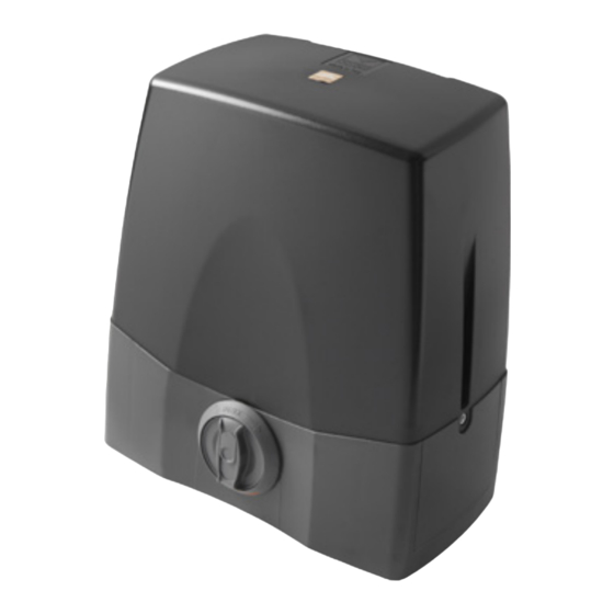
Page 7: Istruzioni Per L'installazione
ISTRUZIONI PER L’INSTALLAZIONE Dimensioni d'ingombro e posizionamento del gruppo • Il motoriduttore deve essere installato rispettando il corretto posizionamento: perpendicolare al terreno, in piedi su superficie piana. All rights reserved. Unauthorised copying or use of the information contained in this document is punishable by law perpendicolare al terreno - Il motoriduttore è... -
Page 8: Programmatore Elettronico
All rights reserved. Unauthorised copying or use of the information contained in this document is punishable by law horised copying or use of the information contained in this document is punishable by law MANOVRA MANUALE CON MOTORE SBLOCCATO PROGRAMMATORE ELETTRONICO L'operazione di sblocco va fatta a motore fermo. - Page 9 Collegamenti morsettiera TUTTI I CONTATTI N.C. NON UTILIZZATI VANNO PONTICELLATI Di conseguenza i test sulle sicurezze corrispondenti (FI, FS) devono essere disabilitati. 1-2 MOT alimentazione motore Se si vuole attivare il test sulle FI, FS sia la parte trasmittente che la parte ricevente (per cambiare il senso di rotazione invertire i cavi 1 e 2 di tali sicurezze vanno collegate ai carichi controllati (CTRL24Vdc).
- Page 10 PROCEDURA DI PROGRAMMAZIONE (impostazione dei parametri) • Tutti le funzioni della centralina sono impostabili tramite menu sul Display "LCD1" con i tre tasti posti sotto ad esso: - utilizzare le freccie per navigare all'interno dei menù e/o per la regolazione del contrasto del display; - utilizzare "PROG/OK"...
-
Page 11: Selezione Della Lingua
• È necessario impostare i parametri di funzionamento fondamentali (es. installazione destra/sinistra) al menu opzioni. • Se sono presenti delle sicurezze con contatto 8.2k, cambiare l'impostazione al menu sicurezze. • Prima di procedere alla programmazione della corsa del cancello impostare il motore corretto alla voce "selezione motore" del menu "MOTO". Selezione della lingua: OPZIONI OPZIONI... -
Page 12: Procedura Di Programmazione
Modulo di memoria (MM) PROCEDURA DI PROGRAMMAZIONE Estraibile, costituito da una memoria non volatile di tipo EEPROM, contiene i (corsa del cancello e sensore di corrente) codici dei trasmettitori e permette la memorizzazione di 300 codici S4XX / 1000 codici S500. Nel modulo di memoria i codici vengono mantenuti anche in assenza •... -
Page 13: Modalità Di Funzionamento
COLLEGAMENTO ANTENNA FUNZIONAMENTO A BATTERIA Utilizzare l’antenna accordata ANS400, da collegare al ricevitore mediante cavetto coassiale RG58 (imp. 50Ω) lunghezza max. 15m Il dispositivo permette il funzionamento del sistema anche in assenza di rete. • Il programmatore dispone di un circuito di carica per batteria NiMH a 24V gestito MODALITÀ... -
Page 14: Important Remarks
IMPORTANT REMARKS IMPORTANT REMARKS IMPORTANT REMARKS READ THE FOLLOWING REMARKS CAREFULLY BEFORE PROCEEDING WITH THE INSTALLATION. PAY PARTICU- LAR ATTENTION TO ALL THE PARAGRAPHS MARKED WITH THE SYMBOL . NOT READING THESE IMPORTANT INSTRUCTIONS COULD COMPROMISE THE CORRECT WORKING ORDER OF THE SYSTEM AND CREATE DANGER SITUATIONS FOR THE USERS OF THE SYSTEM. -
Page 15: Installation Instructions
INSTALLATION INSTRUCTIONS Overall dimensions and positioning • The geared motor must be correctly positioned when it is installed: perpendicular to the ground and straight up on flat ground. All rights reserved. Unauthorised copying or use of the information contained in this document is punishable by law perpendicular to the ground - The geared motor unit has been assembled in the factory to be fitted to the LEFT SIDE of the gate (internal view). -
Page 16: Electronic Programmer
All rights reserved. Unauthorised copying or use of the information contained in this document is punishable by law horised copying or use of the information contained in this document is punishable by law MANUAL MANOEUVRE WITH THE MOTOR RELEASED ELECTRONIC PROGRAMMER Manual release is to be carried out with the motor Stopped. - Page 17 Terminal board connections ALL UNUSED NC CONTACTS MUST BE JUMPED and consequently the corresponding security device tests (FI, FS) must also be deactivated. 1-2 MOT motor power supply If you want to activate the FI, FS test both the transmission and receiver parts of (to change the sense of rotation invert the cables 1 and 2 3-4 ENCODER inputs Bl-Gr for the encoder signal the security devices must be connected to the binding post marked (CTRL24Vdc).
- Page 18 PROGRAMMING PROCEDURE (parameter setting) • All the functions of the electronic programmer can be set in the Display menu "LCD1" using the three buttons contained therein: - use the arrows to navigate through the menu and/or to adjust the display contrast; - use "PROG/OK"...
-
Page 19: Language Choice
• Set the main operating parameters (e.g. installation right/left) in the options menu. • If you have safety devices working with 8.2k contacts select the correct setting from the safety device menu. • Before programming the gate travel distances select the correct motor in the "Motion" menu. Language choice: OPTIONS OPTIONS... -
Page 20: Programming Procedure
Memory module (MM) PROGRAMMING PROCEDURE This is extractable, furnished with a non volatile EEPROM type memory, contains (gate travel distance and current sensor) the transmitter codes and allows you to memorise up to 300 codes S4XX / 1000 codes S500 series. The programmed codes are maintained in this module even •... -
Page 21: Function Modes
CONNECTING THE ANTENNA BATTERY POWERED OPERATION Connect an ANS400 tuned antenna using a coaxial cable RG58 (impedance 50Ω) with a maximum length of 15 m. This device allows the propulsion unit to work during blackouts. • The programmer has a built in charger for an NiMH 24V battery that is managed FUNCTION MODES by a dedicated micro controller. -
Page 22: Consignes Importantes
CONSIGNES IMPORTANTES! CONSIGNES IMPORTANTES! CONSIGNES IMPORTANTES! LIRE ATTENTIVEMENT LES CONSIGNES SUIVANTES AVANT DE PROCÉDER À LA POSE. PRÊTER GRANDE ATTENTION À TOUTES LES SIGNALISATIONS QUI SE TROUVENT DANS LE TEXTE. LE NON RES- PECT DE CES CONSIGNES POURRAIT COMPROMETTRE LE BON FONCTIONNEMENT DU SYSTÈME. •... - Page 23 INSTRUCTIONS POUR L’INSTALLATION Dimensions d'encombrement et instructions sur l'implantation du groupe • Le motoréducteur doit être monté en veillant à respecter la bonne position, c’est-à-dire perpendiculaire au sol, debout sur surface plane. All rights reserved. Unauthorised copying or use of the information contained in this document is punishable by law perpendiculaire au sol - Le motoréducteur est assemblé...
-
Page 24: Manœuvre Manuelle Avec Moteur Débrayé
All rights reserved. Unauthorised copying or use of the information contained in this document is punishable by law horised copying or use of the information contained in this document is punishable by law MANŒUVRE MANUELLE AVEC MOTEUR DÉBRAYÉ PROGRAMMATEUR ÉLECTRONIQUE Le déverrouillage ne doit être effectué... - Page 25 Branchements du bornier FAIRE UN PONT SUR TOUS LES CONTACTS N.F. INUTILISÉS en conséquence invalider les tests sur les dispositifs de sécurité correspondants (FI et FS). Si l’on désire 1-2 MOT Alimentation moteur activer le test sur les dispositifs FI et FS, la partie émettrice tout comme la partie réceptrice Pour modifier le sens de rotation, Intervertir les câbles 1 et 2 de ces dispositifs doivent être branchées à...
-
Page 26: Procédé De Programmation (Paramétrage)
PROCÉDÉ DE PROGRAMMATION (paramétrage) • Toutes les fonctions de la centrale sont programmables au moyen du menu sur l'afficheur LCD1 et des trois touche situées sous celui-ci: - utiliser les flèches pour naviguer dans les menus et/ou pour régler le contraste de l'afficheur; - utiliser "PROG/OK"... -
Page 27: Sélection De La Langue
• Les paramètres de fonctionnement fondamentaux (ex. montage à droite/gauche) dans le menu Mémorisations doivent être réglés impérativement. • S’il y a des dispositifs de sécurité avec contact 8.2k, modifier le réglage dans le menu Sécurités. • Avant de lancer la programmation de la course du portail, programmer le moteur à la rubrique "sélection moteur " du menu "MOUVEMENT". Sélection de la langue: OPTIONS OPTIONS... -
Page 28: Procédé De Programmation
Module de mémoire (MM) PROCÉDÉ DE PROGRAMMATION Amovible, il est constitué d’une mémoire non volatile de type EEPROM qui contient (course du portail et senseur de courant) les codes des émetteurs et permet la mémorisation de 300 codes S4XX / 1000 codes S500. -
Page 29: Fonctionnement À Batterie
BRANCHEMENT DE L'ANTENNE FONCTIONNEMENT À BATTERIE Brancher l'antenne accordée ANS400 au récepteur au moyen d'un câble coaxial RG58 (impédance 50Ω) d'une longueur max. de 15 m. Le dispositif permet le fonctionnement du système même en cas de coupure de courant. MODES DE FONCTIONNEMENT •... -
Page 30: Wichtige Hinweise
WICHTIGE HINWEISE WICHTIGE HINWEISE WICHTIGE HINWEISE VOR DER INSTALLATION SOLLTEN DIE NACHSTEHENDEN HINWEISE AUFMERKSAM GELESEN WERDEN. BESON- DERE AUFMERKSAMKEIT SOLLTE ALLEN IM TEXT BEFINDLICHEN HINWEISEN GESCHENKT WERDEN. DEREN NICHTBEACHTUNG KÖNNTE DEN ORDENTLICHEN BETRIEB DES SYSTEMS BEEINTRÄCHTIGEN UND AKUTE GEFAHRENSITUATIONEN FÜR DEN BEDIENER UND DIE BENUTZER DES SYSTEMS VERURSACHEN. •... - Page 31 INSTALLATIONSANLEITUNGEN Außenabmessungen und Anleitungen zur Positionierung der Gruppe • Der Getriebemotor muss in der richtigen Position installiert werden: senkrecht zum Boden, aufrecht auf ebener Fläche. All rights reserved. Unauthorised copying or use of the information contained in this document is punishable by law senrecht zum Boden •...
-
Page 32: Elektronische Steuerung
All rights reserved. Unauthorised copying or use of the information contained in this document is punishable by law horised copying or use of the information contained in this document is punishable by law HANDBETÄTIGUNG BEI AUSGEKUPPELTEM MOTOR ELEKTRONISCHE STEUERUNG Die Entriegelung muss bei stillstehendem Motor ausgeführt werden. Steuerungseinheit für Gleichstrommotor mit eingebautem Empfänger, der die Spei- Zur Entriegelung des Torflügels sollte der mit der Apparatur mitgelieferte Schlüssel cherung von 300/1000 Benutzercodes ermöglicht (siehe "Fernbedienung", Seite... - Page 33 Anschlussklemmleisten-Anschlüsse ALLE NICHT VERWENDETEN N.C.-KONTAKTE MÜSSEN ÜBERBRÜCKT und somit auch die Tests der entsprechenden Sicherheitsvorrichtungen (FI, FS) ausgeschaltet werden. 1-2 MOT Motor-Stromversorgung Wenn die Tests für FI, FS aktiviert werden sollen, müssen sowohl der sendende als auch der (für den Wechsel der Drehrichtung die Kabel 1 und 2 umkehren) empfangende Teil dieser Sicherheitsvorrichtungen an die kontrollierten Stromverbraucher 3-4 ENCODER Eingänge Bl-Gr für Signale Encoder (CTRL 24 Vdc) angeschlossen werden.
- Page 34 PROGRAMMIERVERFAHREN (Einstellungen der Parameter) • Alle Funktionen des Steuergeräts können über das Menü im Display "LCD1" mit den drei darunterliegenden Tasten eingestellt werden: - Für das Navigieren im Menü und/oder die Einstellung des Kontrasts im Display die Pfeile benutzen; - “PROG/OK” für die Änderung der Einstellung des ausgewählten Parameters und/oder für die Bestätigung benutzen. PROGRAM OPTIONEN OPTIONEN...
-
Page 35: Auswahl Der Sprache
• Die wichtigsten Betriebsparameter (z.B. Installation rechts/links) müssen im Speichermenü eingestellt werden. • Wenn Sicherheitsvorrichtungen mit Kontakt 8.2 kΩ, vorhanden sind, ist die Einstellung im Menü Sicherheitsvorrichtungen zu ändern. • Vor der Programmierung des Torlaufs ist der richtige Motor unter der Position "Motorauswahl" des Menüs "Bewegung" auszuwählen. Auswahl der Sprache: OPTIONEN OPTIONEN... - Page 36 Speichermodul (M1) PROGRAMMIERVERFAHREN Herausnehmbar, verfügt über nicht flüchtigen EEPROM-Speicher, beinhaltet die (Torlauf und Stromsensor) Sendercodes und ermöglicht die Speicherung von 300 Codes Serie S4XX oder 1000 Codes Serie S500. Die Codes verbleiben im Speicher auch in Abwesenheit • Das Vorhandensein der Öffnungs- und Schließungsanschläge ist obligatorisch. der Stromversorgung.
- Page 37 ANTENNENANSCHLUSS BATTERIEBETRIEB Eine abgestimmte Antenne ANS400 benutzen, die über ein Koaxialkabel RG58 (imp. 50Ω) mit einer Länge von max. 15 m an den Empfänger anzuschließen ist. Die Vorrichtung erlaubt den Betrieb des Systems auch bei fehlender Netzversor- gung. BETRIEBSART • Die Steuerung verfügt über einen Ladekreis für NiMH-Batterien auf 24V, der gesteuert wird von einem eigenen Mikrocontroller, der die Spannung abhängig vom 1) Automatisch Zustand der Batterie regelt.
-
Page 38: Advertencias Importantes
ADVERTENCIAS IMPORTANTES ADVERTENCIAS IMPORTANTES ADVERTENCIAS IMPORTANTES LÉANSE ATENTAMENTE LAS SIGUIENTES ADVERTENCIAS ANTES DE PROCEDER CON LA INSTALACIÓN DEL SISTEMA. PRESTAR PARTICULAR ATENCIÓN A TODAS LAS SEÑALIZACIONES QUE HAN SIDO INDI- CADAS EN EL TEXTO , YA QUE EL INCUMPLIMIENTO DE LAS MISMAS PODRÍA PERJUDICAR EL BUEN FUNCIONAMIENTO DEL SISTEMA. -
Page 39: Instrucciones Para La Instalación
INSTRUCCIONES PARA LA INSTALACIÓN Dimensiones maximas y instrucciones para la colocación del grupo • El motorreductor debe instalarse respetando el posicionamiento correcto: perpendicular al terreno, de pie sobre la superficie plana. All rights reserved. Unauthorised copying or use of the information contained in this document is punishable by law perpendicular al terreno •... -
Page 40: Programador Electrónico
All rights reserved. Unauthorised copying or use of the information contained in this document is punishable by law horised copying or use of the information contained in this document is punishable by law MANIOBRA MANUAL CON MOTOR DESEMBRAGADO PROGRAMADOR ELECTRÓNICO La operación de desbloqueo de la cancilla debe realizarse con el motor parado. - Page 41 Conexionado placa de bornes TODOS LOS CONTACTOS N.C. QUE NO SE UTILICEN DEBEN PUENTEARSE y, en consecuencia, deben deshabilitarse los test en los dispositivos de seguridad corres- 1-2 MOT alimentación motor pondientes (FI y FS). Si se habilita el test en FI y FS, tanto la parte emisora como la (Para cambiar el sentido de rotación invertir los cables 1 y 2) parte receptora de dichos dispositivos de seguridad deben ser conectadas a las cargas 3-4 ENCODER entradas Bl-Gr para señales encoder...
- Page 42 PROCEDIMIENTO DE PROGRAMACIÓN (configuración de los parámetros) • Todas las funciones de la centralita pueden configurarse mediante el menú en el Display "LCD1" con las tres teclas situadas debajo del mismo: - utilizar las flechas para navegar en los menús y/o para regular el contraste del display; - utilizar "PROG/OK"...
-
Page 43: Selección Del Idioma
• Es necesario configurar los parámetros de funcionamiento fundamentales (p. ej.: instalación derecha/izquierda) en el menú memorizaciones. • Si hay seguridades con contacto 8.2 kΩ, cambiar la configuración en el menú seguridades. • Antes de efectuar la programación de la carrera de la cancilla, configurar el motor correcto en la posición "selección motor" del menú "MARCHA". Selección del idioma : OPCIONES OPCIONES... -
Page 44: Procedimiento De Programación
Módulo de memoria (MM) PROCEDIMIENTO DE PROGRAMACIÓN Extraíble, consta de una memoria no volátil tipo EEPROM, contiene los códigos (carrera de la cancilla y sensor de corriente) de los emisores y permite guardar en la memoria 300 códigos S4XX y 1000 códigos S500. -
Page 45: Modo De Funcionamiento
CONEXIÓN ANTENA FUNCIONAMIENTO A BATERÍA Utilizar la antena sintonizada ANS400, que se conecta al receptor mediante cable coaxial RG58 (imp. 50Ω) longitud máx. 15 m. El dispositivo permite el funcionamiento del sistema también cuando falta la corriente. • El programador dispone de un circuito de carga para batería NiMH a 24V diri- MODO DE FUNCIONAMIENTO gido por un microcontrolador dedicado que regula la tensión en relación con 1) Automático... -
Page 46: Belangrijke Opmerkingen
BELANGRIJKE OPMERKINGEN BELANGRIJKE OPMERKINGEN BELANGRIJKE OPMERKINGEN OM HET GEVAAR VAN ERNSTIG OF DODELIJK LETSEL TE VERMINDEREN, DIENT U HET ONDERSTAANDE ZORGVULDIG TE LEZEN ALVORENS VERDER TE GAAN MET DE INSTALLATIE. BESTEED MET NAME AANDACHT AAN DE PARAGRAFEN DIE GEMARKEERD WORDEN MET HET SYMBOOL ALS U DEZE BELANGRIJKE AAN- WIJZINGEN NIET LEEST, KAN DAT GEVOLGEN HEBBEN VOOR DE CORRECTE WERKING VAN HET SYSTEEM. -
Page 47: Installatie-Instructies
INSTALLATIE-INSTRUCTIES Buitenafmetingen en aanwijingen voor het plaatsen van de motor • De tandwielmotor moet in de juiste positie worden geïnstalleerd: rechtop en loodrecht op een vlakke ondergrond. All rights reserved. Unauthorised copying or use of the information contained in this document is punishable by law rechtop en loodrecht op een vlakke ondergrond •... - Page 48 All rights reserved. Unauthorised copying or use of the information contained in this document is punishable by law horised copying or use of the information contained in this document is punishable by law DE MOTOR VRIJZETTEN EN DE POORT HANDMATIG BEWEGEN ELEKTRONISCHE PROGRAMMEEREENHEID De motor moet worden gestopt om de poort vrij te zetten en handmatig te bewegen.
- Page 49 Terminal bedrading ALLE GEBRUIKTE NC CONTACTEN moeten gesprongen worden en ook moet je de bijbehorende beveiligingsapparaat testen (FI, FS) uitschakelen. 1-2 MOT motor voeding Als u de FI wilt activeren, FS test het transmissie en ontvanger onderdeel van de beveilig- (Om de draairichting om te keren de kabels 1 en 2 te wijzigen) ingsapparaten die aangesloten worden op de gemarkeerde bindende post (CTRL24Vdc).
- Page 50 PROGAMMEER PROCEDURE (parameter instellingen) • Alle functies van de elektronische programmer kunnen worden ingesteld in het scherm menu "LCD1" met de drie knoppen daarin opgenomen: Gebruik de pijlen om te navigeren door het menu en / of contrast van de display aan te passen. Gebruik "PROG / OK"...
- Page 51 • Zet de belangrijkste operationele parameters (zoals installatie rechts / links) in het optiemenu. • Als de veiligheidsvoorzieningen werken met 8.2k contacten, selecteert u de juiste instelling van de veiligheidvoorzieningen. • Voor het programmeren van de poort reisafstanden selecteert u de juiste motor in het "Beweging" menu. Taalkeuze: •...
- Page 52 Geheugen module (MM) PROGRAMMERING PROCEDURE Dit is uittrekbaar, ingericht met een niet vluchtig EEPROM type geheugen en bevat de (poort reisafstand en de huidige sensor ) zender codes en kunt u maximaal memoriseren tot 300 codes S4XX / 1000 codes •...
- Page 53 AANSLUITEN VAN DE ANTENNE WERKING OP BATTERIJ Sluit een ANS400 afgestemde antenne met een coaxiale kabel RG58 (impedantie 50Ω) met een maximale lengte van 15 m aan. Deze besturing kan de aandrijving aan het werk houden tijdens black-outs. • De programmer heeft een ingebouwde lader voor een NiMH 24V batterij die wordt beheerd door een speciaal micro-controller.
- Page 54 NOTES:...
- Page 55 NOTES:...
-
Page 56: Technical Specifications
CARATTERISTICHE TECNICHE DIMENSIONI D’INGOMBRO - EXTERNAL DIMENSIONS - Alimentazione DIMENSIONS D’ENCOMBREMENT - Frequenza AUSSENABMESSUNGEN - DIMENSIONES MAXIMAS - Corrente nominale - Potenza assorbita - Intermittenza di lavoro - Velocità di traslazione m/min - Coppia max. - Temperatura di esercizio °C -20°…+55 - Grado di protezione Dati motore:...