Whirlpool HYBRIDCARE Instructions D'installation
Table des Matières
Les langues disponibles
Les langues disponibles
Liens rapides
HYBRIDCARE
PUMP DRYER
INSTALLATION
INSTRUCTIONS
Table of Contents
DRYER SAFETY ......................................................................... 2
INSTALLATION REQUIREMENTS ............................................. 3
Tools and Parts ...................................................................... 3
LOCATION REQUIREMENTS .................................................... 4
DRAIN SYSTEM ......................................................................... 5
ELECTRICAL REQUIREMENTS - U.S.A. ONLY ....................... 6
ELECTRIC DRYER POWER HOOKUP - CANADA ONLY ........ 7
INSTALL LEVELING LEGS ......................................................... 8
ELECTRICAL INSTALLATION - U.S.A. ONLY .......................... 8
Power Supply Cord Connection ........................................... 9
Direct Wire Connection ....................................................... 11
CONNECT OUTLET HOSE ...................................................... 14
LEVEL DRYER .......................................................................... 15
COMPLETE INSTALLATION CHECKLIST .............................. 16
DOOR REVERSAL (OPTIONAL) .............................................. 16
TROUBLESHOOTING .............................................................. 20
Para una version de estas instrucciones en español, visite www.Whirlpool.com o www.maytag.com
INSTALLATION NOTES
_________________________________
Date of purchase:
_______________________________
Date of installation:
________________________________________
Installer:
___________________________________
Model number:
___________________________________
Serial number:
HEAT
™
SÉCHEUSE À POMPE À
CHALEUR HYBRIDCARE
INSTRUCTIONS
D'INSTALLATION
Table des matières
SÉCURITÉ DE LA SÉCHEUSE ................................................ 21
EXIGENCES D'INSTALLATION ............................................... 22
Outillage et pièces ............................................................... 22
EXIGENCES D'EMPLACEMENT ............................................. 23
SYSTÈME DE VIDANGE .......................................................... 24
CANADA SEULEMENT ............................................................ 25
INSTALLATION DES PIEDS DE NIVELLEMENT .................... 26
CONNEXION DU TUYAU DE SORTIE ..................................... 26
RÉGLAGE DE L'APLOMB DE LA SÉCHEUSE........................ 27
ACHEVER L'INSTALLATION LISTE DE VÉRIFICATION ......... 28
INVERSION DE LA PORTE (FACULTATIF) .............................. 28
DÉPANNAGE ...................................... COUVERTURE ARRIÈRE
NOTES CONCERNANT L'INSTALLATION
_____________________________________
Date d'achat :
________________________________
Date d'installation :
______________________________________
Installateur :
________________________________
Numéro de modèle :
__________________________________
Numéro de série :
™
W11184511A
W11184519A - SP
Table des Matières
Dépannage

Manuels Connexes pour Whirlpool HYBRIDCARE


Sommaire des Matières pour Whirlpool HYBRIDCARE
-
Page 21: Sécurité De La Sécheuse
SÉCURITÉ DE LA SÉCHEUSE Certaines pièces internes sont intentionnellement non reliées à la terre et peuvent présenter un risque de choc électrique uniquement lors d’une intervention de dépannage. Personnel d’entretien - Ne pas toucher le support du thermostat lorsque l’appareil est sous tension. -
Page 22: Exigences D'installation
EXIGENCES D’INSTALLATION OUTILLAGE ET PIÈCES Pièces fournies: Rassembler les outils et composants nécessaires avant d’entreprendre l’installation. Outillage nécessaire : Tuyau flexible de vidange Pieds de nivellement (4) de 6 pi (1,82 m) avec raccords Tournevis à lame plate Tournevis Phillips n° 2 Pince à... -
Page 23: Exigences D'emplacement
EXIGENCES D’EMPLACEMENT DIMENSIONS DE LA SÉCHEUSE Vue de face : Vérifier les spécifications des codes. Certains codes limitent 27" (686 mm) ou interdisent l’installation des sécheuses dans un garage, un placard, une maison mobile ou une chambre à coucher. Contacter l’inspecteur en bâtiments local. "... -
Page 24: Distances De Dégagement Recommandées Pour L'installation (Sécheuse Seulement)
SYSTÈME DE VIDANGE Espacement pour une installation dans un encastrement ou dans un placard : Le système de vidange peut être installé à l’aide d’un conduit Les dimensions indiquées correspondent à l’espacement d’évacuation au plancher, un tuyau rigide de rejet à l’égout mural, minimal permis. -
Page 25: Sécheuse Électrique Raccordementà L'alimentation Électrique - Canada Seulement
■ S’assurer que le raccordement électrique est adéquat et Système de vidange dans un évier de buanderie conforme au Code canadien de l’électricité, C22.1 – dernière édition, et à tous les codes locaux en vigueur. Pour obtenir un exemplaire des normes des codes ci-dessus, contacter : Canadian Standards Association, 178 Rexdale Blvd., Toronto, 4.5"... -
Page 26: Installation Des Pieds De Nivellement
INSTALLATION DES PIEDS CONNEXION DU TUYAU DE SORTIE DE NIVELLEMENT Fixation du tuyau Préparer la sécheuse pour les pieds Fixer le raccord col-de-cygne du tuyau de vidange de de nivellement 6 pieds (1,82 m) fourni à l’électrovanne de vidange en bas du panneau arrière de la sécheuse. -
Page 27: Réglage De L'aplomb De La Sécheuse
RÉGLAGE DE L’APLOMB DE LA SÉCHEUSE Réglage de l’aplomb de la sécheuse Place Placer level here le niveau ici Vérifier l’aplomb de la sécheuse d’un côté à l’autre. Répéter l’opération de l’avant vers l’arrière. REMARQUE : La sécheuse doit être d’aplomb pour que le système de détection d’humidité... -
Page 28: Achever L'installation Liste De Vérification
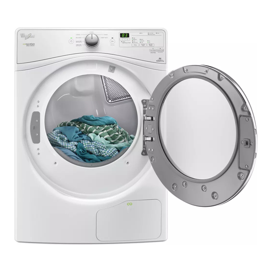
INVERSION DE LA PORTE ACHEVER L’INSTALLATION LISTE (FACULTATIF) DE VÉRIFICATION Les instructions suivantes correspondent aux modèles avec Ɨ Vérifier que toutes les pièces sont maintenant installées. S’il portes arrondies. reste une pièce, passer en revue les différentes étapes pour découvrir laquelle aurait été oubliée. Outils nécessaires : Ɨ... -
Page 29: Toutes Les Portes
TOUTES LES PORTES : Dégager la porte interne de la porte externe Retirer la porte de la sécheuse Haut de la porte IMPORTANT : Si l’on n’a pas encore retire la pellicule protectrice de la sécheuse, la décoller de la porte de la sécheuse avant de continuer. -
Page 30: Enlever Le Loquet
Enlever le loquet Réinstaller la charnière sur l’autre côté Section mince Loquet Section épaisse Inverser et faire pivoter l’intérieur de porte de 180° pour que Inverser l’intérieur de porte vers la gauche. À l’aide d’un la section mince se situe en haut et la section épaisse en bas. tournevis T20 , réinstaller la charnière sur le côté... -
Page 31: Replacer L'ensemble De Rotation Et Le Tube
TOUTES LES PORTES : Replacer l’ensemble de rotation et le tube Réinstaller l’intérieur de porte Ouvrir vers le bas Replacer l’ensemble de rotation et le tube de 180°, du côté Bas de opposé de la porte. la porte Faire tourner la base de l’ensemble Positionner la porte de façon à... -
Page 32: Dépannage
DÉPANNAGE PORTES AVEC ÉCRAN ACL : Voir le Guide d’utilisation et d’entretien ou consulter notre site Reconnecter le câblage Web et la “Foire aux questions” pour tenter d’éviter le coût d’une intervention de réparation. Brancher le câblage. À l’aide d’un tournevis cruciforme, fixer l’ensemble de rotation à...