Publicité
Liens rapides
I
ISTRUZIONI PER IL MONTAGGIO DEL MANIGLIONE SERIE
59301 e 59351
AVVERTENZE: Le caratteristiche di questi prodotto rivestono la massima importanza per
la sicurezza delle persone e non è consentito apportare al prodotto modifiche diverse da
quelle descritte in queste istruzioni. Questo prodotto va installato su porte a cardine o
cerniera che non superino i 200 kg di massa, 2500 mm di altezza e 1300 mm di larghezza.
L'articolo è ambidestro (fig. 1) quindi applicabile su porte di mano destra e su porte di
mano sinistra. La rappresentazione grafica del presente foglio istruzione è relativa ad un
maniglione in configurazione per porte di mano sinistra interna "2". Questo maniglione
va montato in abbinamento alla barra art. 07007-13/14/15/60/61/62
F
INSTRUCTIONS DE MONTAGE DE LA POIGNEE ANTI-PANIQUE
série 59301 et 59351
ATTENTION: Le respect des caractéristiques de ce produit est extrêmement important
pour la sécurité des personnes. Il n'est pas permis d'apporter au produit d'autres
modifications que celles qui sont décrites dans ces instructions. Installer ce produit sur
des portes à gonds ou à charnières ne dépassant pas 200 kg, 2500 mm de hauteur et 1300
mm de largeur. L'article est ambidextre (fig. 1) et donc applicable sur des portes à main
droite et gauche. La représentation graphique de ces instructions correspond à une
poignée pour portes à main gauche interne "2". Monter cette poignée associée à la barre
art. 07007-13/14/15/60/61/62
NL
MONTAGEHANDLEIDING VOOR ANTI-PANIEKSLOT SERIE 59301
en 59351
WAARSCHUWINGEN: de eigenschappen van dit product zijn buitengewoon belangrijk
voor de veiligheid van de mens en het is daarom niet toegestaan andere wijzigingen aan
het product aan te brengen dan in deze handleiding aangegeven. Dit product is bestemd
voor gescharnierde deuren met een niet grotere massa dan 200 kg, een hoogte tot 2500
mm en een breedte tot 1300 mm. Het artikel is dubbelzijdig (afb. 1), daarom zowel op
linkse als rechtse deuren van toepassing. In de tekening op de handleiding wordt een
bijzetslot voor installatie aan de binnenkant op een linkse deur "2" afgebeeld. Dit product
moet in combinatie met de anti-paniek duwstang art. 07007-13/14/15/60/61/62
gemonteerd worden
1
2
FIG. 1
GB
INSTRUCTION SHEET FOR THE PANIC EXIT DEVICES SERIES
59301 and 59351
WARNING: The characteristics of this product are essentially important for people's
safety. No product changes different from those described in these instructions should
be introduced. This product should be installed on hinged doors with a maximum mass
of 200 kg, a maximum height of 2500 mm and a maximum width of 1300 mm.
This item is non-handed (Fig. 1) and may therefore be fitted on both left- and right-handed
doors. The figures in these instruction sheet refer to a panic exit device installed on a left-
hand inward opening door, type "2". This panic exit device (1 point closing) is to be
installed together with the bar item 07007-13/14/15/60/61/62
E
INSTRUCCIONES PARA EL MONTAJE DE LA BARRA SERIE
59301 Y 59351
ADVERTENCIAS: Las características de estos productos tienen la máxima importancia
para la seguridad de las personas. No está permitido realizar modificaciones diferentes
a las descritas en estas instrucciones. Este producto debe ser instalado en puertas con
goznes o bisagras que no superen 200 kg de masa, 2500 mm de altura y 1300 mm de
ancho. El artículo es reversible (Fig. 1) y, en consecuencia, puede ser instalado en puertas
de mano derecha o izquierda. La representación gráfica de la presente hoja de instrucciones
corresponde a una barra en configuración para puertas de mano izquierda interna "2".
Esta barra se debe instalar en combinación con la barra Art. 07007-13/14/15/60/61/62.
D
MONTAGEANLEITUNG FÜR DIE TÜRDRÜCKER SERIE 59301
UND 59351
HINWEIS: Die Eigenschaften dieses Produktes sind für die Personen-Sicherheit von
höchster Wichtigkeit, deshalb ist es streng untersagt, Änderungen vorzunehmen, die von
den in diesen Anleitungen angeführten abweichen. Das vorliegende Produkt wird auf
Türen mit Angeln oder Scharnieren angebracht, geeignet für Türen mit einem Gewicht
von max.200 kg, einer Höhe von max. 2500 mm und einer Breite von max. 1300 mm.
Der Artikel ist beidseitig verwendbar (Abb. 1), d.h. er kann für links- oder rechtsgerichtete
Öffnung verwendet werden. Die Abbildungen auf dem vorliegenden Blatt beziehen sich
auf einen Türdrücker, der für nach links und nach innen öffnende Türen "2" konfiguriert
ist. Dieser Türdrücker muss in Kombination mit der Stange Art. 07007-13/14/15/60/61/
62 montiert werden.
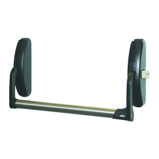
3
1 = Piastra fissaggio maniglione
Panic exit device fixing plate
Plaque de fixation poignée
Placa fijación cerradura
Bevestigingsplaat anti-paniekslot
Türdrücker-Befestigungsplatte
2 = Bocchetta
Striker
Gâche
Batiente
Schootplaat
Beschlag
3 = Barra (07007-13/14/15/60/61/62)
Bar (07007-13/14/15/60/61/62)
Barre (07007-13/14/15/60/61/62)
Barra (07007-13/14/15/60/61/62)
Duwstang (07007-13/14/15/60/61/62)
Stange (07007-13/14/15/60/61/62)
1
Publicité

Manuels Connexes pour CISA 59301 Série

Sommaire des Matières pour CISA 59301 Série
- Page 1 INSTRUCTION SHEET FOR THE PANIC EXIT DEVICES SERIES ISTRUZIONI PER IL MONTAGGIO DEL MANIGLIONE SERIE 59301 e 59351 59301 and 59351 WARNING: The characteristics of this product are essentially important for people’s AVVERTENZE: Le caratteristiche di questi prodotto rivestono la massima importanza per safety.
- Page 2 COMANDI ESTERNI APPLICABILI (da richiedere a parte) (fig. 2): art. 07077-47-0: Placca con maniglia. art. 07077-48-0: Placca con maniglia e cilindro sagomato art. 0G304-02 corredato di tre chiavi: in posizione di chiuso la maniglia è in folle. art. 07077-49-0: Placca con cilindro sagomato 0G304-09 corredato di tre chiavi. art.
- Page 3 PREPARAZIONE: 1) Verificare il buono stato della porta e la sua planarità. Tracciare a porta chiusa un asse orizzontale G-D alla distanza di 1117 mm dal pavimento (fig. 3). 2) Scegliere la bocchetta adatta al tipo di installazione da effettuare (fig. 4A e fig. 4B) e fissare con adesivo le dime sulla porta (fig.
- Page 4 INSTALLAZIONE: 3) Segnare con un punteruolo la posizione dei fori necessari (vedi dime posizionate sulla porta). Eseguire i fori (i diametri di seguito indicati sono indicativi per i profili di alluminio): H1 = 3.5 mm (n° 8 fori di cui 4 per scatola principale e 4 per scatola secondaria) (fig 5). NEL CASO DI MONTAGGIO CON COMANDI ESTERNI art.
- Page 5 5) DETERMINAZIONE MANO DEL MANIGLIONE: L’articolo viene fornito di mano SX (fig. 1), per cambiare mano eseguire le seguenti operazioni sulla SCATOLA PRINCIPALE: (fig. 6). Svitare il perno staffa, sfilare i due perni. Ruotare la staffa di 180°, sfilare la spina da 8 mm dalla sua posizione ed inserirla dalla parte opposta (fig.
- Page 6 6) Fissare la scatola principale e quella secondaria alla porta, installare il comando esterno quando presente secondo le istruzioni riportate negli specifici fogli istruzione. 7) Posizionare le borchie plastiche sulle staffe (fig. 8). 8) Montare i carter fissandole alla scatola utilizzando le quattro viti da M3 x 6 in dotazione con l’avvertenza di inserirvi, in alto ed in basso sui carter, i collari chiusi di raccordo (fig.
- Page 7 MONTAGGIO BOCCHETTA: 12) Posizionare le bocchette a battuta sullo scrocco utilizzando il numero di spessori necessari per rispettare la distanza indicata nelle fig. 14A e fig. 14B; Segnare con un punteruolo i due fori laterali (asole) ed eseguire i due fori H3 = 2,6 mm (indicativo per profili di alluminio) (fig.
- Page 8 CISA. Zij kunnen het model adviseren dat het meest past bij de specifieke ONDERHOUD: Zie onderhoudsinstructies voor de eindgebruiker.