Dimas WS 325 Manuel D'utilisation
Liens rapides
DIMAS WS 325
Operator's manual
Read these instructions carefully and make
sure you understand them before using
DIMAS WS 325.
Manuel d'utilisation
Lire attentivement et bien assimiler le
manuel d'utilisation avant de se servir
DIMAS WS 325.
Bedienungsanweisung
Lesen Sie die Bedienungsanweisung
sorgfältig durch und machen Sie sich mit
dem Inhalt vertraut, bevor Sie
DIMAS WS 325 benutzen.
Manual de Instrucciones
Antes de utilizar DIMAS WS 325 lea bien el
manual de instrucciones hasta comprender
su contenido.

Manuels Connexes pour Dimas WS 325


Sommaire des Matières pour Dimas WS 325
- Page 1 Bedienungsanweisung Lesen Sie die Bedienungsanweisung sorgfältig durch und machen Sie sich mit dem Inhalt vertraut, bevor Sie DIMAS WS 325 benutzen. Manual de Instrucciones Antes de utilizar DIMAS WS 325 lea bien el manual de instrucciones hasta comprender su contenido.
- Page 2 Read all the operating Read, understand and follow all Always use eye and ear instructions before using or warnings and instructions in protectors when using the carrying out service these operating instructions and machine. procedures on the machine on the machine Il est important de lire, de Lisez le mode d’emploi dans Portez toujours une protection...
- Page 3 Our aim in designing the Dimas wall saw was to produce equipment that can be divided into several units so that it can be managed by one person and operated as efficiently as possible at every stage of the process, including all transport and movement around the site. The working range and cutting depth were chosen to suit the likely applications and the available power.
- Page 4 WARNING! Under no circumstances must the power unit or the machine be modified from the original version without the permission of the manufacturer. Unapproved modifications can result in serious personal injury or even death. WARNING! These machines can be dangerous if they are used carelessly or incorrectly, and this can lead to serious accidents and in the worst instance fatal accidents.
- Page 5 Contents Introduction ______________________________________________________________________________ 2 Safety instructions _________________________________________________________________________ 5 Technical data ___________________________________________________________________________ 13 What is what? ___________________________________________________________________________ 17 Presentation _____________________________________________________________________________ 18 Assemble the equipment ___________________________________________________________________ 20 Starting procedure ________________________________________________________________________ 27 Starting Procedure and Sawing ______________________________________________________________ 30 Maintenance ____________________________________________________________________________ 31 Transport _______________________________________________________________________________ 33 Conformance with EU directives _____________________________________________________________ 34 Table des matières Introduction ______________________________________________________________________________ 2...
- Page 6 During the design and manufacture of Dimas products great emphasis is placed on ensuring that they are not only effective and easy to use, but also safe. To ensure that the machine remains safe you must pay attention to the following: 1.
- Page 7 18. Check that hoses are connected correctly to the tool and that the hydraulic couplings lock as intended before applying pressure to the hydraulic system. Couplings are locked by turning the outer sleeve on the female coupling so that the slot comes away from the ball. Pressure hoses in the system must always be connected to the tool’s intake.
- Page 8 Lors de la construction et de la fabrication des produits Dimas, une grande attention a été portée à l’efficacité, à la maniabilité et à la sécurité. Certains points doivent par conséquent être observés en vue de préserver le haut degré de sécurité de l’appareil :...
- Page 9 18. Contrôlez que les flexibles sont correctement raccordés à l’outil, et que les les raccords hydrauliques se verrouillent correctement avant de mettre le système hydraulique sous pression. Pour verrouiller les raccords, tournez le manchon de la prise femelle de manière à libérer la bille de la rainure de blocage.
- Page 10 Gefahrensituation beim Arbeiten mit der Maschine ausführlich darzustellen. Durch gesunden Menschenverstand können die meisten Unfälle verhindert werden. Bei der Konstruktion und Herstellung von Dimas-Produkten liegt unser Hauptaugenmerk auf Effektivität, Benutzerfreundlichkeit und Sicherheit. Beachten Sie Folgendes, um einen sicheren Maschinenbetrieb zu gewährleisten: 1.
- Page 11 18. Vergewissern Sie sich, dass die Schläuche korrekt an das Werkzeug angeschlossen sind und die Hydraulikkupplungen ordnungsgemäß verriegelt wurden, bevor das Hydrauliksystem unter Druck gesetzt wird. Um die Kupplungen zu verriegeln, drehen Sie die Außenhülse der Buchsenkupplung, wodurch sich die Nut von der Kugel entfernt. Die Druckschläuche des Systems sind stets an den Werkzeugeinlass anzuschließen.
- Page 12 No obstante, el operador puede prevenir accidentes utilizando siempre el sentido común. En el diseño y fabricación de los productos Dimas se ha concedido una importancia primordial a que, además de ser eficaces y fáciles de manejar, también sean seguros. Para mantener la seguridad de la máquina hay que considerar varios factores: 1.
- Page 13 18. Antes de presurizar el sistema hidráulico, comprobar que las mangueras estén correctamente conectadas en la herramienta y que los acoplamientos hidráulicos están fijados como es debido. Los acoplamientos se fijan girando el manguito exterior del acoplamiento hembra de forma que la ranura se aparte de la bola. Las mangueras de presión del sistema deben conectarse siempre en la entrada de la herramienta.
- Page 14 Fig. 1 Technical data Specified hydraulic power output __________________ 9,2 kw (12,3 hp) Hydraulic oil flow ______________________________ 40 l/min (10,6 US gal/min) Pressure, max ________________________________ 210 bar (2960 psi) Trolley feed __________________________________ manuell Blade feed ___________________________________ manuell Noise level ___________________________________ 78 dB(A) 82 dB(C) Caractéristiques techniques Effet hydraulique ______________________________ 9,2 kw (12,3 hp) Flux d’huile hydraulique _________________________ 40 l/min (10,6 US gal/min)
- Page 15 Fig. 2 Cutting capacity 700 mm (28") blade diameter (max start blade) wall thickness __________________ 300 mm (12") 900 mm (36") blade diameter (max diameter)wall thickness ____________________ 400 mm (16") Capacité de coupage 700 mm (28") diamètre de disque (disque de démarrage maxi) _____________________ Épaisseur de mur 300 mm (12") 900 mm (36") diamètre de disque (diamètre maxi) ____ Épaisseur de mur 400 mm (16") Schnittleistung 700 mm Klingendurchmesser (max.
- Page 16 Fig. 3 Cutting speed m/s, ft/min 24" 28" 36" Blade diameter Blade diameter mm ft/min ft/min ft/min Spindle speed 1100 rpm Spindle speed 1100 rpm Lever position 1, see fig. 6912 8063 10367 Lever position 1, see fig. Vitesse de coupage m/s, ft/min 24"...
- Page 17 Fig. 4 Weight Total weight of complete system: _________________ approx. 80 kg (180 lbs) Individual parts: Wall saw unit: ________________________________ 24 kg (54 lbs) Blade guard diam. 700 mm (28") __________________ 12 kg (27 lbs) Rails _______________________________________ L = 1310 mm (51") 13 kg (30 lbs) _________________ L = 2270 mm (89") ____________________________ 24 kg (55 lbs) Poids Poids total de l’ensemble _______________________ env.
- Page 18 Fig. 5 Fig. 6 What is what? 6. Rail Saw motor 7. Hydraulic hose connections 8. Lock knob, upper 1. Cutting arm 9. Lever, main valve 2. Blade motion 10. Hydraulic motor 3. Cooling water connection 11. Guide wheel, lower 4.
- Page 19 Fig. 7 Fig. 8 Presentation Saw motor Hydraulic hose connections (7) The hoses drive the saw blade. Lock knobs (8, 12) The saw motor is locked on the rails with these. The handles are turned to the click position when setting up the saw.
- Page 20 Fig. 9 Fig. 10 Cooling water connection (3) It cools and lubricates the blade. The other end of the Main Valve (9) hose is normally connected to the power unit. The lever activates the main valve, which starts and stops the saw’s hydraulic motor.
- Page 21 Fig. 11 Fig. 12 Assembling the equipment Fitting the rails Take the equipment to the work site. 1. Mark the cutting line and mark the positions of the drill holes for the expander bolts at a distance of 210 mm (8.25") from the Check that the supply voltage is suited to the power unit.
- Page 22 Fig. 13 Fig. 14 5. Place the rail between the wall mountings and tighten the 7. Adjust the distance between the cutting line and the wall compression washers (A). The rack should be closest to the mounting. The distance between the edge of the wall mounting cutting line.
- Page 23 Fig. 15 1. Remove the stop plates from the ends of the rails. Extending the Rail 2. Clean the contact surfaces on the ends of the rails and position For longer cuts, the rail may need extending. To this end, them next to each other.
- Page 24 Fig. 16 Fig. 17 Assembling the saw 2. Lock the handles (8, 12) on the saw unit until a ”click” is heard. The clicking noise indicates that the saw has been assembled 1. Hang the saw unit on the rail. Place the trolley’s guide wheels correctly.
- Page 25 Fig. 19 Fig. 18 Assembling the saw blade 4. If the cutting arm is not cranked: 3. Fit the handle (1) or telescopic trolley motion crank (2). Crank out the cutting arm with the hand crank. The blade The stop screws, which hold the locking balls found on the tools, rotates anticlockwise when viewed from the screw side.
- Page 26 Fig. 20 Fig. 21 Fit the blade guard. 5. Remove any dirt from the contact surfaces on the blade flange and blade. Fit the three sections of the blade guard. Check that the 6. Fit the blade. Check that the guide pin hooks in as intended. lock hooks lock as intended.
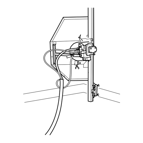
- Page 27 Fig. 22 Fig. 23 Connect the water hose Connect the hydraulic hoses Check that the ball valve on the water hose is closed. Check that the main valve is set to 0. Connect the hose between the intake (3) on the cutting Clean any dirt from the hydraulic hoses and the saw’s (7) arm and the hydraulic unit’s cooler (or other water quick connectors.
- Page 28 Fig. 25 Fig. 24 Start procedure and sawing Connect the telescopic trolley motion rod or handle. 1. Start the power unit. Upper (2) = Blade motion 2. Turn the main valve (9) to position 1 to start the blade. Lower (13) = Trolley motion WARNING! A higher speed than the recommended speed...
- Page 29 Fig. 26 Fig. 27 5. Move the saw trolley along the rail with the telescopic trolley 3. Open the ball valve on the water hose to obtain a suitable flow. motion rod or handle. Move the saw at a rate at which the 4.
- Page 30 Fig. 29 Fig. 28 6. Once you have made the guide cut, repeat the procedure from Stop the blade after sawing through by returning the step 4 onwards until you have cut through the wall. The depth of main valve to position 0. the cut will vary from situation to situation.
- Page 31 Fig. 30 Dismantling the equipment NOTE! 1. Allow the motor to stop completely. The electric motor on the unit must stop completely. 2. Disconnect the power supply cable before disconnecting the Always clean all the equipment at the end of the working water hoses.
- Page 32 The cutting arm (1) contains 0.4 litres (0.42 USqt) of the underside of the cutting arm. Dimas Oil 150, a transmission oil of the EP 150 grade. The oil should be changed for the first time after one Always clean the magnetic plug when it is removed.
- Page 33 Fig. 33 Fig. 34 Cleaning Tightening torque If you carry out repairs or maintenance that require It is important to clean all the equipment. It is a good idea to disconnect the water cooling hose or the blade from the removal and refitting of any screws they should be cutting arm and use this to wash down the saw unit, blade retightened to the following torque:...
- Page 34 Fig. 35 Transport The saw unit, rails, blade guard and even the hose assembly should be stored in the strong plywood Freight weights: cases that the equipment was supplied in. Large case (containing saw unit, hose assembly, etc.) _ 50 kg (112 lbs) Long case (containing rails, etc.) _________________ 50 kg (112 lbs) Apart from providing safe storage, these cases Small case (containing blade guard) _______________ 25 kg (56 lbs)
- Page 35 Compliance with EU directives Dimas AB, Box 2098, S-550 02 Jönköping, Sweden, tel: + 46 36 570 60 00, hereby certifies that Wall Saw WS 325, from serial number 01001 and onwards, are manufactured in accordance with Council’s machinery directive 98/37/EEC, low-voltage directive 73/23/EEC and directive 89/336/EEC on electromagnetic compatibility, with amendments, and that the follow standards have been used for guidance: EN 55 014-1, EN 55 014-2, EN 61 000-3-2, and EN 50 144-1.
- Page 36 531 12 16-42 2004 W17...