Dimas PP 325 E Manuel D'utilisation
Groupe d'alimentation électrohydraulique
Table des Matières
Liens rapides
DIMAS PP 325 E
Operator's manual
GB
Read these instructions carefully and
make sure you understand them before
using PP 325 E.
Manual de
E
Instrucciones
Antes de utilizar PP 325 E lea bien el
manual de instrucciones hasta
comprender su contenido.
Bedienungsanweisung
D
Lesen Sie die Bedienungsanweisung
sorgfältig durch und machen Sie sich
mit dem Inhalt vertraut, bevor Sie
PP 325 E benutzen.
Manuel d'utilisation
F
Lire attentivement et bien assimiler le
manuel d'utilisation avant de se servir
PP 325 E.
Table des Matières

Manuels Connexes pour Dimas PP 325 E


Sommaire des Matières pour Dimas PP 325 E
- Page 1 Read these instructions carefully and make sure you understand them before using PP 325 E. Manual de Instrucciones Antes de utilizar PP 325 E lea bien el manual de instrucciones hasta comprender su contenido. Bedienungsanweisung Lesen Sie die Bedienungsanweisung sorgfältig durch und machen Sie sich mit dem Inhalt vertraut, bevor Sie PP 325 E benutzen.
- Page 2 Read the entire operator's manual Read, understand and follow all warnings Always wear eye and ear protectors when before using or servicing this unit. and instructions in this manual and on the using this unit. unit. Lea, comprenda y siga todas las Antes de utilizar o hacer el servicio de Utilice siempre protecciones para los ojos advertencias y demás instrucciones de este...
-
Page 3: Introduction
El PP 325 E es un grupo energético electro-hidráulico destinado principalmente a la sierra de pared WS 325, al motor de taladro Dimas DM 406 HH y a la sierra de mano Dimas HH 170. No obstante, el grupo también es adecuado para la propulsión de otros equipos del ramo;... -
Page 4: Warnings And Safety Instructions
NOTE! This manual covers the hydraulic portion of the power pack. For service not described in this manual, please contact an authorized dealer. WARNING! Under no condition should this power pack be modified from its original design without permission from the manufacturer. -
Page 5: Table Des Matières
Index Introduction ________________________________________________________ 2 Warnings and safety instructions ______________________________________ 3,5 What is what? ______________________________________________________ 9 Technical data ____________________________________________________ 10 Before your Hydraulic Power Pack is put in use __________________________ 12 Power Pack couplers _______________________________________________ 13 Before Starting ____________________________________________________ 14 Starting procedure _________________________________________________ 15 After the job is done ________________________________________________ 16 Transport ________________________________________________________ 17 Maintenance ______________________________________________________ 17... -
Page 6: General Safety Precautions
Great importance has been attached to efficiency, ease of use as well as safety during the design and manufacture of Dimas’ products. However, in order for the machine to remain safe some issues need to be observed: 1. Working near electrical lines. -
Page 7: Warn- Und Sicherheitshinweise
Warn- und Sicherheitshinweise Bei der Konstruktion und Herstellung von Dimas Produkten wurde größter Wert darauf gelegt, dass diese nicht nur möglichst effektiv und einfach zu handhaben, sondern auch sicher sind. Damit das Gerät auch sicher bleibt, sind bestimmte Dinge zu beachten: 1. -
Page 8: Instrucciones Generales De Seguridad
Instrucciones generales de seguridad En el diseño y fabricación de los productos Dimas se concede una importancia suma a que, además de ser eficaces y fáciles de usar, también sean seguros. Para mantener la seguridad de la máquina, deben tenerse en cuenta varios aspectos. -
Page 9: Consignes Générales De Sécurité
Consignes générales de sécurité Lors de la construction et de la fabrication des produits Dimas, une attention toute particulière a été portée à leur sécurité d'utilisation, en plus de leur efficacité et de leur simplicité de manipulation. Certaines consignes doivent être prises en compte afin que la machine reste sûre:... -
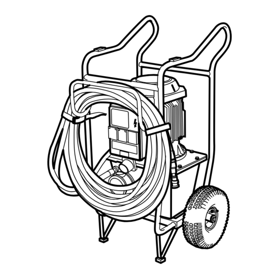
Page 10: What Is What
Fig. 1 What is what? Teilebezeichnung 1. Rack for hydraulic hoses 1. Bügel für Hydraulikschlauch 2. Hydraulic system pressure gauge 2.Druckölmanometer 3. Oil level gauge 3. Ölmesser 4. Hydraulic oil tank 4. Tank, Hydrauliköl 5. Drain plug hydraulic oil 5. Ablaßschrauben, Hochdrucköl 6. -
Page 11: Technical Data
Fig. 2 Fig. 3 Technical Data Motor _________________________________ Electrical 380 – 420 V, 16 A, 50 Hz Flow _________________________________ Max 40 litres/min (10 gpm) Hydraulic Tank Capacity _________________ 12 litres (3,2 US gallons, 2.6 UK gallons) Cooling _______________________________ Water via separate hose Dimensions ____________________________ W = 575 mm, H = 1040 mm, L = 780 mm, (W = 23", H = 41", L = 31") Weight (dry) ___________________________ 93 kg (205 lbs dry) Datos técnicos... - Page 12 Fig. 4 Fig. 5 Noise level acc. to ISO/DIS 11201 __________ Sound pressure at operator's ear no load 80 dB(A), full load 83 dB(A). Noise emmissions acc. to Directive 2000/14/EC ____________________________ Measured noise level 94 dB(A). Guaranteed noise level 99 dB(A) Hose length (1/2"...
-
Page 13: Before Your Hydraulic Power Pack Is Put In Use
Fig. 7 Fig. 6 Before your Hydraulic Power Pack is put in Inflate tires. Check tires for proper inflation; 2 bar (30 psi). Check the oil level The unit is delivered with 12 litres of hydraulic oil, viscosity 46 cSt HSH, of a well-known brand. The oil is an environmentally adapted, Swedish Testing and Research Institute approved ester oil, which significantly reduces the risk of allergic reactions or skin irritation in the event of any... -
Page 14: Power Pack Couplers
Fig. 9 Fig. 8 Connections Connect a water hose between the upper radiator Wipe away any dirt from the hydraulic hoses’ quick- connection on the hydraulic oil tank and the tool; and connectors and connect them. The connectors are locked connect a hose from the closest water source to the by turning the outer ring on the female connector so that lower radiator connection on the tank via a faucet. -
Page 15: Before Starting
Fig. 10 Fig. 11 Before Starting Hydraulic oil Electrical Connection Check the level at the sight glass on tank. Connect the incoming electrical cable (16 A). This must be a three-phase, earthed cable. A neutral wire is also Minimum level = red line. needed for the single-phase outputs on the electrical Maximum level = black line. -
Page 16: Starting Procedure
Fig. 12 Fig. 13 Starting procedure 1. Start the electric motor. Turn the switch to the ”Y” If one of the green lamps comes on, everything is position in the direction indicated by the lit green lamp. okay. The motor’s direction of travel will then be correct. If none of the green lamps come on there is no power. -
Page 17: After The Job Is Done
Fig. 14 Fig. 15 After the job is done 2. Adjust the water faucet to a water flow suitable for the appropriate tool. 1. Turn off the electric motor. Even if the tool does not require water, cooling water 2. Let the motor come to a complete stop. shall still flow through the radiator and thereafter to the 3. -
Page 18: Transport
Fig 16 Transport Maintenance Tightening torque The power unit is designed as a cart offering the possibility to hang the hydraulic hoses for easy movement between During repair and maintenance that requires dismantling sites. with subsequent reassembly and tightening of bolts the following tightening torque should be used: When transporting between sites, the power unit is stored horizontally with the distribution box upwards. - Page 19 Fig. 17 Fig. 18 Hydraulic oil The hydraulic oil should be changed as needed or once Hydraulic oil is filled through the filter at the front of the each year. tank. Position the unit with the filter housing turned upwards. Remove the filter housing cover by removing The oil draining plug is at the bottom of the oil tank.
- Page 20 Fig. 20 Fig. 19 Hydraulic oil filter Cleaning The filter shall be changed twice yearly. Position the unit Clean the unit regularly by wiping it with a cloth. with the filter housing turned upwards. Remove the filter housing cover by removing the three screws. Lift up the WARNING filter cartridge.
-
Page 21: Declaración Ce De Conformidad
Assurance de conformité CE Dimas AB, Box 2098, SE-550 02 Jönköping, Suède, tél. : +46 36-570 60 00, certifie par la présente que le groupe d’alimentation PP 325 E, à partir des numéros de série 01001 et ultérieurs, est fabriqué conformément à la directive du Conseil 98/37/CE sur les machines, à la directive 73/23/CEE sur les faibles tensions et à... - Page 22 531 14 12 -51 2004W17...