Husqvarna 333R Manuel D'utilisation
Table des Matières
Les langues disponibles
Les langues disponibles
Liens rapides
Manuel d'utilisation (EPA)
Operator's manual (EPA)
333R 335FR 335R
X-series
F F F F r r r r e e e e n n n n c c c c h h h h ( ( ( ( 2 2 2 2 - - - - 3 3 3 3 6 6 6 6 ) ) ) )
Lire attentivement et bien assimiler le manuel d'utilisation avant d'utiliser la machine.
Please read the operator's manual carefully and make sure you understand the instructions before using the machine.
E E E E n n n n g g g g l l l l i i i i s s s s h h h h ( ( ( ( 3 3 3 3 7 7 7 7 - - - - 7 7 7 7 1 1 1 1 ) ) ) )
Chapitres
Table des Matières

Manuels Connexes pour Husqvarna 333R


Sommaire des Matières pour Husqvarna 333R
- Page 1 Manuel d’utilisation (EPA) Operator’s manual (EPA) 333R 335FR 335R X-series F F F F r r r r e e e e n n n n c c c c h h h h ( ( ( ( 2 2 2 2 - - - - 3 3 3 3 6 6 6 6 ) ) ) ) Lire attentivement et bien assimiler le manuel d’utilisation avant d’utiliser la machine.
-
Page 2: Explication Des Symboles
EXPLICATION DES SYMBOLES Symboles AVERTISSEMENT! Les Destiné uniquement à des débroussailleuses et les coupe- équipements de coupe flexibles et non herbes peuvent être dangereux! métalliques, c’est-à-dire les têtes de Une utilisation erronée ou désherbage avec fil. négligente peut occasionner des blessures graves, voire mortelles pour l’utilisateur ou d’autres personnes. -
Page 3: Table Des Matières
SOMMAIRE Sommaire Contrôler les points suivants avant la mise en marche: EXPLICATION DES SYMBOLES Lire attentivement le manuel d’utilisation. Symboles L’entretien, le remplacement ou la réparation des dispositifs SOMMAIRE et des systèmes antipollution peuvent être effectués par tout Sommaire établissement ou personne qui répare des produits motorisés Contrôler les points suivants avant la mise en manuels. -
Page 4: Introduction
Cher client, Félicitations pour ce choix d’un produit Husqvarna. Husqvarna a vu le jour en 1689 lorsque le roi Karl XI décida de construire un arsenal pour la fabrication des mousquets au bord de la rivière Huskvarna. Le choix de l’emplacement était logique puisque la rivière Huskvarna servait à... -
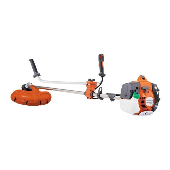
Page 5: Quels Sont Les Composants
QUELS SONT LES COMPOSANTS? 335FR 333R Quels sont les composants de la débroussailleuse? Tête de désherbage 18 Contre-écrou Ravitaillement en lubrifiant, renvoi d’angle 19 Bride de support Renvoi d’angle 20 Bol de garde au sol Protection pour l’équipement de coupe 21 Toc d’entraînement... -
Page 6: Instructions Générales De Sécurité
INSTRUCTIONS GÉNÉRALES DE SÉCURITÉ Important! AVERTISSEMENT! Ne jamais laisser des enfants utiliser la machine ou se tenir à IMPORTANT! proximité. La machine est équipée d'un interrupteur d'arrêt à détente et peut être La machine n’est construite que pour le désherbage, le démarrée par une activation à... -
Page 7: Équipement De Sécurité De La Machine
INSTRUCTIONS GÉNÉRALES DE SÉCURITÉ Équipement de sécurité de la PROTÈGE-YEUX Toujours porter des protège-yeux homologués. L’usage machine d’une visière doit toujours s’accompagner du port de lunettes de protection homologuées. Par lunettes de Ce chapitre présente les équipements de sécurité de la protection homologuées, on entend celles qui sont en machine, leur fonction, comment les utiliser et les conformité... - Page 8 INSTRUCTIONS GÉNÉRALES DE SÉCURITÉ Appuyer sur le blocage de l’accélération et vérifier qu’il Protection pour l’équipement de coupe revient de lui-même en position initiale quand il est relâché. Cette protection a pour but d’empêcher que des objets ne soient projetés en direction de l’utilisateur. La protection prévient aussi le contact entre l’utilisateur et l’équipement de coupe.
- Page 9 INSTRUCTIONS GÉNÉRALES DE SÉCURITÉ Le système anti-vibrations réduit la transmission des Certains harnais sont également équipés d’une plaque vibrations de l’unité moteur/l’équipement de coupe à pectorale à libération rapide au niveau du crochet de l’unité que constituent les poignées. suspension. S’assurer du bon positionnement des bretelles du harnais.
-
Page 10: Équipement De Coupe
INSTRUCTIONS GÉNÉRALES DE SÉCURITÉ Ne jamais utiliser une machine dont le silencieux est Contre-écrou défectueux. Un contre-écrou est utilisé pour la fixation de certains types d’équipements de coupe. Vérifier régulièrement la fixation du silencieux dans la machine. Pose: serrer l’écrou dans le sens contraire de la rotation de l’équipement de coupe. - Page 11 INSTRUCTIONS GÉNÉRALES DE SÉCURITÉ recommandé. Une lame mal affûtée ou endommagée AVERTISSEMENT! Toujours arrêter le augmente les risques d’accident. moteur avant d’entamer des travaux sur l’équipement de coupe. Celui-ci continue de tourner après qu’on a relâché l’accélérateur. S’assurer que l’équipement de coupe est complètement immobilisé...
- Page 12 INSTRUCTIONS GÉNÉRALES DE SÉCURITÉ Affûtage de la lame d’éclaircissage • Ajuster l’avoyage. Il doit être de 1 mm. • Voir les instructions d’affûtage sur l’emballage de l’équipement de coupe. Un affûtage correct de la lame est une condition indispensable pour l’obtention d’un travail efficace et pour éviter une usure anormale de la lame et de la débroussailleuse.
-
Page 13: Montage
MONTAGE Montage du guidon et de la Montage de l’équipement de poignée d’accélération coupe AVERTISSEMENT! Lors du montage de l’équipement de coupe, il est de la plus grande • Démonter la vis à l’arrière de la poignée importance que la commande du bras d’accélération. -
Page 14: Montage Du Protège-Lame, De La Lame À Herbe Et Du Couteau À Herbe
MONTAGE ensuite le bouclier à la protection combinée à l’aide des • Monter l’écrou (G). Serrer l’écrou au couple de quatre fixations rapides. serrage de 35-50 Nm (3,5-5 kpm). Utiliser la clé à douille du jeu d’outils. Tenir le manche de la clé le plus près possible du protège-lame. -
Page 15: Montage Des Autres Protections Et Équipements De Coupe
MONTAGE • Monter un toc d’entraînement (B) sur l’axe sortant. Montage des autres protections • Faire tourner l’axe de la lame jusqu’à ce que l’un des et équipements de coupe trous du toc d’entraînement coïncide avec le trou correspondant du carter. •... -
Page 16: Adaptation Du Harnais Et De La Débroussailleuse
MONTAGE Adaptation du harnais et de la Hauteur correcte débroussailleuse Déblayage forestier Pour le débrousaillage forestier, la machine doit être portée dans le harnais de manière à ce que l'équipement AVERTISSEMENT! Lors de travail avec de coupe penche légèrement vers l'avant par rapport au une débroussailleuse, toujours sol. - Page 17 MONTAGE Réglage du harnais Afin de transmettre une charge plus importante de la courroie des épaules à celle des hanches, serrer Serrer la courroie des hanches afin qu’elle soit bien davantage la bande élastique (B). stable. Serrer la courroie qui passe autour de la poitrine sous le bras gauche afin qu’elle soit bien ajustée contre le corps.
-
Page 18: Manipulation Du Carburant
Afin d’assurer un rapport de optimaux, utiliser une huile moteur deux temps mélange correct, il est important de mesurer avec HUSQVARNA fabriquée spécialement pour nos précision la quantité d’huile à mélanger. Pour le mélange moteurs deux temps à refroidissement à air. -
Page 19: Remplissage De Carburant
MANIPULATION DU CARBURANT Remplissage de carburant • Rapport de mélange 1:50 (2%) avec huile deux temps HUSQVARNA. Huile deux temps, litres Essence, litres 2% (1:50) AVERTISSEMENT! Les mesures de 0,10 sécurité ci-dessous réduisent le risque 0,20 d’incendie: 0,30 Ne jamais fumer ni placer d’objet chaud à... -
Page 20: Démarrage Et Arrêt
DÉMARRAGE ET ARRÊT Contrôles avant la mise en carter de protection si l’un ou l’autre a subi des dommages ou présente des fissures. marche • Contrôler la lame afin de détecter d’éventuelles fissures au niveau des dents et du trou central. Les raisons les plus fréquentes de la présence de fissures sont la formation de coins pointus lors de l’affûtage et l’utilisation d’une lame aux dents émoussées. - Page 21 DÉMARRAGE ET ARRÊT jusqu’à ce que le carburant commence à remplir la poche. Pour poignée d’accélération avec Il n’est pas nécessaire de remplir la poche complètement. blocage de l’accélération au démarrage: Pour passer sur la position accélération au démarrage, appuyer d’abord sur le blocage de la commande d’accélération et la commande d’accélération, puis appuyer sur le bouton de l’accélération au démarrage (A).
-
Page 22: Techniques De Travail
TECHNIQUES DE TRAVAIL Méthodes de travail fondrières, etc. Observer la plus grande prudence lors de travail sur des terrains en pente. IMPORTANT! Ce chapitre traite des consignes de sécurité de base lors du travail avec une débroussailleuse ou un coupe- herbe. - Page 23 TECHNIQUES DE TRAVAIL L’ABC du déblayage Méthodes de travail • Toujours utiliser un équipement adéquat. AVERTISSEMENT! Les machines • Toujours utiliser un équipement correctement adapté. équipées de lames d’éclaircissage ou de disques à herbe peuvent être projetées • Respecter les consignes de sécurité. violemment d’un côté...
- Page 24 TECHNIQUES DE TRAVAIL également le parcours en fonction du vent afin que les la lame amène la partie inférieure de l’arbre vers la troncs déblayés tombent dans la partie déjà déblayée. gauche. • Pour faire chuter l’arbre en avant, tirer la partie inférieure de l’arbre vers l’arrière.
- Page 25 TECHNIQUES DE TRAVAIL Débroussaillage avec une lame • Si on penche légèrement la lame vers la gauche pendant le débroussaillage, l’herbe coupée est d’éclaircissage disposée en bandes, ce qui facilite le ramassage, par exemple lors du ratissage. • Essayer d’adopter un rythme de travail régulier. Prendre une position stable, les pieds écartés.
- Page 26 TECHNIQUES DE TRAVAIL Nettoyage par grattage • La technique du grattage permet d’enlever toute végétation indésirable. Maintenir la tête de désherbage juste au-dessus du sol, puis l’incliner. Laisser l’extrémité du fil battre le sol autour des arbres, poteaux, statues et similaires. NOTA! Cette technique accélère l’usure du fil.
-
Page 27: Entretien
Les caractéristiques techniques de cette machine sens des aiguilles d’une montre, on obtient un régime Husqvarna assurent des émissions de gaz nocifs réduites de ralenti plus haut; si elle est tournée dans le sens au minimum. Après 8-10 pleins, le moteur est rodé. Pour contraire des aiguilles d’une montre, on obtient un... - Page 28 ENTRETIEN Pointeau L de bas régime endommage le moteur. Ne pas laisser le moteur tourner à plein régime pendant plus de 10 secondes. Chercher le régime de ralenti maximum en tournant le pointeau L. Arrivé au régime maximum, tourner le pointeau L d’un quart de tour dans le sens inverse des aiguilles.
-
Page 29: Silencieux
ENTRETIEN Réglage du régime de ralenti accéléré Silencieux Un réglage situé près de la partie arrière de la poignée d’accélération permet d’obtenir le régime de ralenti accéléré correct. Cette vis (vis hexagonale de 4 mm) permet d’augmenter ou de réduire le régime de ralenti REMARQUE! Certains silencieux sont dotés d’un pot accéléré. -
Page 30: Système De Refroidissement
Toutefois, avant d’utiliser la machine, il convient de s’assurer que le renvoi d’angle est au 3/4 Toujours utiliser l’huile pour filtre HUSQVARNA, réf. 531 rempli de graisse. Utiliser une graisse HUSQVARNA 00 92-48. L’huile pour filtre contient un solvant permettant spéciale. -
Page 31: Bougie
Une bougie incorrecte peut endommager le piston/le cylindre. Remarque: N’utiliser que les pièces de rechange HUSQVARNA. L’utilisation de pièces d’autres marques pourrait endommager votre machine ou encore causer des blessures à l’opérateur ou à d’autres personnes. Votre garantie ne couvre ni les dommages ni la responsabilité... -
Page 32: Schéma D'entretien
ENTRETIEN Schéma d’entretien La liste ci-dessous indique l’entretien à effectuer sur la machine. La plupart des points sont décrits à la section Entretien. L’utilisateur ne peut effectuer que les travaux d’entretien et de révision décrits dans ce manuel d’utilisation. Les mesures plus importantes doivent être effectuées dans un atelier d’entretien agréé. -
Page 33: Caractéristiques Techniques
CARACTÉRISTIQUES TECHNIQUES Caractéristiques techniques Caractéristiques techniques 333R 335FR 335RX Moteur Cylindrée, po 2,11/34,6 2,11/34,6 2,11/34,6 Alésage, po/mm 1,50/38,0 1,50/38,0 1,50/38,0 Course, po/mm 1,20/30,5 1,20/30,5 1,20/30,5 Régime de ralenti, tr/min 2900 2900 2900 Régime d'emballement maximal recommandé, tr/min 11500 11500 11500 Régime de l’axe sortant, tr/min... - Page 34 CARACTÉRISTIQUES TECHNIQUES Protection pour équipement de Accessoires homologués Type coupe, réf. Trou central des lames/couteaux Ø 25,4 mm Axe de lame fileté M12 Multi 255-3 (Ø 255 3 dents) 537 33 16-01 Grass 255-4 (Ø 255 4 dents) 537 33 16-01 Lame/couteau à...
-
Page 35: Déclaration De Garantie Contrôle Des Émissions En Californie Et Au Niveau Fédéral
EPA (U.S. Environmental Protection Agency), CARB moteur ou l’équipement est livré à l’acheteur final. (California Air Resources Board), Environment Canada et Husqvarna Forest & Garden ont le plaisir d’expliquer la DURÉE DE LA GARANTIE garantie relative au système de contrôle des émissions Husqvarna Forest &... - Page 36 DEMANDE D’INDEMNITÉ Si vous avez des questions concernant vos droits et charges en garantie, contactez votre revendeur autorisé le plus proche ou téléphonez à Husqvarna Forest & Garden, au numéro suivant: +1-800-487-5963. SERVICE APRÈS-VENTE Les révisions ou réparations sous garantie sont disponibles auprès de tous les revendeurs agréés...
- Page 73 8,5 m 10 cm 4" 4,2 m "Clic" 15 cm 6"...
- Page 74 4,25 m 4,25 m 15 cm 6" 15 cm 6"...
- Page 75 T35, T35x 8,5 m 10 cm 4" 4,3 m "Clic" 15 cm 6"...
- Page 76 T45, T45x 10 m 10 cm 4" 4,3 m 15 cm "Clic" 6"...
- Page 77 Auto 55 >1,1 Kw <1,1 Kw 2,7 mm - 9,0 m 3,0 mm - 7,5 m 3,3 mm - 6,0 m 15 cm 6" 15 cm 6" 15 cm 15 cm 6" 6"...
- Page 78 Trimmy SII 7,0 m 12 cm 5" ~ 3,5 m ~ 15 cm "Clic" 35-50 NM...
- Page 84 1151115-32 ´®z+S+U¶2z¨ ´®z+S+U¶2z¨ 2008-03-06...