Publicité
Liens rapides
RECORD MODEL NUMBER:
81T2__ 1__ A - __ - MMO-▲
VALVE TYPE
0
Water Closet (W/C)
3
Urinal
TYPE DE
SOUPAPE
0
Toilettes
3
Urinoir
▲Specify Finish / Précisez la Finition
PLEASE LEAVE the Maintenance & Installation (M&I) manual with owner for maintenance and troubleshooting information.
VEUILLEZ LAISSER Le Guide d'entretien et d'installation du propriétaire pour les informations d'entretien et de dépannage.
POWER OPTION
BT
Battery
HW
Hardwired
OPTION
D'ALIMENTATION
BT
Pile
HW
Câblé
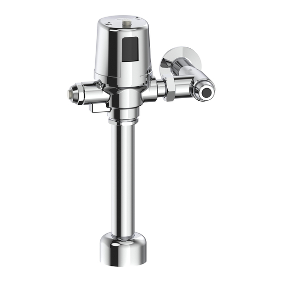
Commercial - Electronic Exposed
TECK
(with H2Optics
Commercial - Robinet de chasse
Électronique TECK
(La technologie H2Optics
ALTERNATE FLUSH VOLUMES
Blank
Adjustable flush (W/C and Urinal)
42
4.2 Lpf (1.1 gpf) fixed flush (W/C only)
48
4.8 Lpf (1.27 gpf) fixed flush (W/C only)
05
0.5 Lpf (0.125 gpf) fixed flush (Urinal only)
AUTRES VOLUMES DE CHASSE
Vide
Chasse d'eau réglable (toilette et urinoir)
42
chasse fixe de 4,2 Lpf (1,1 gpf)
(seulement pour les toilettes)
48
chasse fixe de 4,8 Lpf (1,27 gpf)
(seulement pour les toilettes)
05
chasse fixe de 0,50 Lpf (0,13 gpf)
(seulement pour l'urinoir)
213631, Rev. A
II Flush Valve
®
Technology)
®
II à découvert
MD
MMO -
Manual Mechanical Override
MMO -
Surpassement mécanique manuel
)
MD
Publicité

Manuels Connexes pour Delta Faucet TECK II 81T201BTA-MMO

Sommaire des Matières pour Delta Faucet TECK II 81T201BTA-MMO
- Page 1 Commercial - Electronic Exposed TECK II Flush Valve ® (with H2Optics Technology) ® Commercial - Robinet de chasse Électronique TECK II à découvert (La technologie H2Optics RECORD MODEL NUMBER: 81T2__ 1__ A - __ - MMO-▲ MMO - VALVE TYPE POWER OPTION ALTERNATE FLUSH VOLUMES Manual Mechanical Override...
- Page 2 Installation Specification / Spécification d’installation Flushometer MUST be paired with a fixture of equivalent flush Figure 1 volume. DIMENSIONAL TABLE (see Figure 1) Product Min. Max. Min. Max. Min. 81T201BTA-MMO/ * 140mm 292mm 81T201HWA-MMO (52”) (112”) All variations* 110mm 132mm 54mm (4a”)
- Page 3 Installation/ Installation Figure 2 It is important to FLUSH and thoroughly CLEAN water lines to ELIMINATE contaminants • (example - scale, sediment, gravel, cuttings, solder, etc.). STEP 1 - INLET ADAPTER INSTALLATION (see Figure 2) 1. Cut the end of the 1” Copper Inlet Tube (A) so that it is 1” from centre line of Fixture Spud (B).
- Page 4 STEP 3 - FLUSHOMETER INSTALLATION Figure 4 (see Figure 4) 1. Assemble vacuum breaker components (B, C, D) into the outlet tube (E). 2. Assemble the outlet tube with vacuum breaker onto the flushometer body (A) and tighten coupling nut (F) into the flushometer body. 3.
- Page 5 STEP 5A - POWER CONNECTION Figure 6 (Hardwire models) (see Figure 6) 1. Install the plastic bushing (A) into the hole on the coverplate (B). 2. Remove screws (C) and cover (D) from the flushometer (E) 3. Measure (aa) and cut tube assembly (F) to appropriate length, so that the tube assembly will fit under the cover (D) and the other end will go into the electical box (G) through the plastic bushing in the coverplate by 1/2”...
- Page 6 STEP 5B - POWER CONNECTION Figure 7 (Battery models) (see Figure 7) The batteries are already installed and the product is in hibernation mode waiting to be activated. 1. Remove the yellow label (B). 2. Push the electronic override button (C) three times within five seconds to activate the valve and to place it into operation mode.
- Page 7 Flush Volume Adjustment / Réglage Du Volume De Chasse Adjustable Models (listed below) Fixed Non-Adjustable Models (listed below) The Flushometer CANNOT be adjusted according to job conditions and fixture The Regulating Screw (E) may be adjusted according to job conditions and fixture installed to the proper water volume to flush that particular fixture.
- Page 8 Setup Modes / Modes de configuration Optional: Only required if factory settings are not preferred. If adjustments are made within 30 minutes of initial power-up: 1. Proceed to “Setup Modes” . If desired adjustments are not made within 30 minutes of initial power-up. The power must be disconnected for 10 seconds and then reconnected to obtain another adjustment period.
- Page 9 Step 2 - Sensor Adjustment Setting Figure 11 A. Cycle through the bowl length or Urinal sensing distance by pressing the electronic override button (A). Operation Mode / Mode de fonctionnement B. Verify bowl length or Urinal sensing distance (see “Sensor Adjustment Verification / Vérification Du Réglage Du Capteur”...
- Page 10 Sensor Adjustment Verification / Vérification Du Réglage Du Capteur For Water Closets: (see Figure 12) Figure 12 1. Configure the sensing ranges based on the appropriate bowl length (aa) for the installation. 2. Verify the correct distance is selected by: i.
- Page 11 Battery Strength Indicator / Indicateur De Charge (see Figure 13) (voir la Figure 13) 1. During Operation Mode - press and hold down the electronic override button (A) for Figure 13 approximately 10 seconds. DO NOT RELEASE the button when solid blue light is present - keep holding down. 2.
- Page 12 Repair Parts/ Pièces de Rechange Page - 12 of 25 213631, Rev. A...
- Page 13 Item No./ Part No./ Description Article N° de Pièce 061063A Replaceable Lens for 3rd Generation E-FV Lentille remplaçable pour E-FV de 3e Génération 061138A * Cover Screws for 3rd Generation E-FV (2/pkg) Capuchon de vis pour E-FV de 3e Génération 061139A Metal Cover Couvercle en métal...
- Page 14 Table 1 - Cap/Pin/Diaphragm Configuration Table Tableau 1 – Table de Configuration du Capuchon/Tige/Diaphragme Urinal/Urinoir Water Closet/ Toilette *Fixed / Adjustable / *Fixed / Adjustable / *Non Réglable Ajustable *Non Réglable Ajustable **0.5 Lpf 1.9 Lpf **4.2 Lpf **4.8 Lpf 6.0 Lpf (0.125 gpf) (0.5 gpf)
- Page 15 Troubleshooting / Dépannage • We recommend that you use only genuine Delta replacement parts. ® DO NOT USE EXCESSIVE FORCE to close the inlet stop stem. We RECOMMEND that the flushometer be flushed while closing the inlet stop. The noise •...
- Page 16 Problem Indicator Cause Solution Valve will not Flushometer has been Re-assembled incorrectly. Check that the Cap/Solenoid Assembly has been put on the body properly. flush serviced and DOES NOT The Regulating Screw should always be on the same side as the inlet stop. operate Lights operate as expected Solenoid not connected to...
- Page 17 Troubleshooting / Dépannage • Nous vous recommandons également d’utiliser uniquement des pièces de rechange de marque Delta N’EXERCEZ PAS UNE FORCE EXCESSIVE pour fermer la tige de l’arrêt d’admission. Nous vous RECOMMANDONS d’activer le robinet de chasse en • fermant l’arrêt d’admission.
- Page 18 Problème Voyant Cause Solution Chasse par Le robinet de chasse Le capteur nécessite un Voir la section “Chasse d’eau par Inadvertance (voir la Figure 17)” à la inadvertance. s’active sans que ajustement pour permettre la page 20 pour les instructions sur le réglage de l’angle du capteur. personne n’utilise réflexion du signal infrarouge.
- Page 19 BATTERY REPLACEMENT (see Figure 15) Figure 15 • Use of high quality Alkaline Batteries recommended when replacing. • All previously adjusted settings will be retained when batteries are changed. 1. Remove the two cover screws (A) and lift off metal cover (B). 2.
- Page 20 INADVERTENT FLUSHING (See Figure 17) Figure 17 1. Check for the presence of a mirror or reflective surface across from the flushometer. 2. Cover the reflective surface by standing in front or with paper, if this resolves the inadvertent flushing then: 3.
- Page 21 CAP/SOLENOID & REGULATING SCREW ASSEMBLY MAINTENANCE (see Figure 18) Figure 18 1. Close the supply stop (K). 2. Remove the cover (B) by taking out the 2 cover screws (A). 3. Carefully lift the electronic compartment (C) off the cap/solenoid & regulating screw assembly (F), disconnect the solenoid wires from the electronic compartment (C).
- Page 22 DIAPHRAGM/GUIDE ASSEMBLY AND SEAT MAINTENANCE (see Figure 19) Figure 19 1. Close the supply stop (K). 2. Remove the cover (B) by taking out the 2 cover screws (A). 3. Carefully lift the electronic compartment (C) off the cap/solenoid & regulating screw assembly (F), disconnect the solenoid wires from the electronic compartment (C).
- Page 23 MMO BUTTON MAINTENANCE (see Figure 20) Figure 20 1. Close the supply stop (B). 2. Using a wrench (C) remove the capnut (A). 3. Remove the cage assembly (D) from the flushometer body (E). 4. With the cage assembly (D) removed, check for damage to the O-ring (F) and washer (I).
- Page 24 New Jersey: The provisions of this document are intended to apply to the In the United States and Mexico: In Canada: fullest extent permitted by the laws of the State of New Jersey. Delta Faucet Company Masco Canada Limited Additional Rights Product Service...
- Page 25 New Jersey.. Aux États-Unis et au Mexique: Au Canada: Droits additionnels Delta Faucet Company Masco Canada Limited Cette garantie vous confère des droits légaux spécifiques, et vous pourriez Product Service Technical Service Centre avoir d’autres droits, lesquels varient d’un état/province à...