Télécharger Imprimer la page

Publicité

Les langues disponibles

Les langues disponibles

Liens rapides

MANUEL D'INSTRUCTIONS
INSTRUCTIONS MANUAL
BEDIENUNGSHANDBUCH
AL 936N
MANUEL D'INSTRUCTIONS
INSTRUCTIONS MANUAL
BEDIENUNGSHANDBUCH
AL 936N
2 x 0 - 30V 0 - 3A
2 - 5,5V 3A or 5,5V - 15V 1A
2 x 0 - 30V 0 - 3A
2 - 5,5V 3A or 5,5V - 15V 1A
ALIMENTATION STABILISEE
STABILIZED POWER-SUPPLY
STABILISIERTES NETZGERÄT
ALIMENTATION STABILISEE
STABILIZED POWER-SUPPLY
STABILISIERTES NETZGERÄT

Publicité

loading

Sommaire des Matières pour ELC AL 936N

  • Page 1 MANUEL D'INSTRUCTIONS INSTRUCTIONS MANUAL BEDIENUNGSHANDBUCH 2 x 0 - 30V 0 - 3A AL 936N 2 - 5,5V 3A or 5,5V - 15V 1A ALIMENTATION STABILISEE STABILIZED POWER-SUPPLY STABILISIERTES NETZGERÄT MANUEL D'INSTRUCTIONS INSTRUCTIONS MANUAL BEDIENUNGSHANDBUCH 2 x 0 - 30V 0 - 3A...
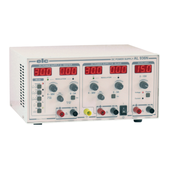
  • Page 2 AL 936N DC POWER SUPPLY DC POWER SUPPLY A - MASTER DC POWER SUPPLY B - SLAVE AUXILIARY 2 - 15V Mode REGULATION REGULATION Separate Tracking fine fine 0 - 30V 0 - 3A 0 - 30V 0 - 3A...
  • Page 3 Vous venez d’acquérir l’ALIMENTATION STABILISEE type elc AL936N. Nous vous 2.5 CARACTERISTIQUES TECHNIQUES page 4 en remercions et vous félicitons de votre choix. elc c’est toute une gamme d’Alimentations mais aussi de nombreux appareils PRINCIPE DE FONCTIONNEMENT page 5 électroniques : G...
  • Page 4 2.3 COMPOSITION DE L’ENSEMBLE DE L’APPAREIL Votre alimentation AL 936N vous est livrée avec son cordon secteur fiche «EUROPE» 2 pôles + terre et son manuel d’instructions. 2.4 SYMBOLES ET DEFINITION Vous trouverez les symboles ci-après sur le matériel :...
  • Page 5 AUTRES CARACTERISTIQUES fonctionne à tension constante pour la valeur de la Fig.1 tension de sortie sélectionnée et avec une limitation RL=Vs/Is Alimentation : Secteur 230V ±10% 50 / 60Hz de courant à Is. RL>Vs/Is Entrée secteur : Embase «EUROPE» CEE 22 avec cordon 2 pôles + terre Si RL varie de l’infini à...
  • Page 6 de la borne négative de l’alimentation maître «A» et la borne positive de l’alimentation esclave «B». La régulation de tension de l’esclave «B» est commandée par celle de Il permet d’obtenir une alimentation réglable de 0 à 30V avec un courant de 0 à 6A. la maître «A».
  • Page 7 1 manuel d’instruction 1 «Bull-pack» 1 enrobage en carton 6.2.1 Vue d’ensemble de la face avant 1 Alimentation : AL 936N 1 cale en carton 1 Cordon secteur 1 AFFICHAGE DU COURANT 4.2 MONTAGE ET MISE EN PLACE DE L’APPAREIL 2 CONTROLE DE LA REGULATION DE COURANT Pour une bonne convection naturelle, l’alimentation doit reposer sur ses 4 butées...
  • Page 8 BORNE POSITIVE MARCHE - ARRET. Le repére O indique la position Arrêt de l’appareil. BORNE NEGATIVE SELECTION DU MODE STANDBY. En position attente LED rouge éclairée, REGLAGE DE LA TENSION aucune tension n’est disponible sur les bornes de sortie des alimentations Permet d’ajuster symétriquement une tension entre 0 et 30V.
  • Page 9 AFFICHAGE DU COURANT (20) BORNE POSITIVE Permet de lire le courant de 0 à 3A avec 10mA de résolution. (21) BORNE NEGATIVE ATTENTION (14) (16) (17) (27) (28) (29) (30) (31) (32) (33) inhibés 6.3 PREPARATIONS POUR LES MESURES MODE "PARALLEL" des alimentations Master et Slave 6.3.1 Alimentations A et B ou Master et Slave (10) SELECTION DU MODE "PARALLEL"...
  • Page 10 9. DECLARATION DE CONFORMITE Les sorties étant flottantes, dans les limites de la tension de mode commun, la suivant l’ISO /IEC guide 22 et l’EN45014 référence est donnée par le montage Fig. 2. L’alimentation peut délivrer une tension positive ou négative. Fabricant Adresse 59 avenue des Romains 74000 Annecy France...
  • Page 11 Page 12 2.1 INTRODUCTION 2.4 SYMBOLS AND DEFINITIONS Page 12 You just bought a POWER SUPPLY type elc AL936N. We thank you and congratulate 2.5 TECHNICAL SPECIFICATIONS Page 12 you for your good choice. The elc company proposes a wide range of POWER SUPPLIES and many other...
  • Page 12 Your power-supply AL 936N is delivered with its mains cord and «EUROPE» bipolar plug + Earth and its instructions manual. You will find following symbols on the instruments : CAUTION ! RISK OF EARTH TERMINAL CAUTION ! TO REFER ELECTRIC SHOCK...
  • Page 13 OTHER SPECIFICATIONS to the adjustments of Vs and Is and to the load applied at the output. If the RL load resistance is higher than the ratio Vs/Is, the power supply works at Mains : 230V ± 10%, 50 / 60Hz constant voltage for the value of the selected output voltage and with a Mains input : «EUROPE»...
  • Page 14 the Slave power-supply "B". The regulation of the slave voltage is driven by the master one. The current setting remains independant and adjustable from It allows to adjust the power-supply from 0 to 30V with a current from 0 to 6A. The 0 to 3A for each power-supply.
  • Page 15 6.2 CONTROLS 1 instructions manual 1 «Bull-pack» wrapping 1 cardboard wrapping 6.2.1 Controls description of the front panel 1 Power-supply : AL 936N 1 cardboard packing piece 1 Mains cord 1 CURRENT DISPLAY 4.2 MOUNTING AND PLACING OF THE INSTRUMENT...
  • Page 16 POSITIVE TERMINAL ON-OFF SWITCH NEGATIVE TERMINAL The graduation O indicates the position of the stop device. VOLTAGE ADJUSTMENT SELECTION OF THE STANDBY MODE Allows to adjust symmetrically a voltage between 0 and 30V. In standby mode with lighting red Led, no voltage is available at the output VOLTAGE FINE ADJUSTMENT terminals of the Master and Slave power-supplies.
  • Page 17 CAUTION (14) (16) (17) (27) (28) (29) (30) (31) (32) (33) are inactive. (20) POSITIVE TERMINAL (21) NEGATIVE TERMINAL PARALLEL MODE of the Master and Slave power-supplies (10) SELECTION OF THE PARALLEL MODE 6.3 BEFORE MEASURING The parallel mode of the 2 power-supplies allows to adjust, between the 6.3.1 A and B power supplies or Master and Slave (13) and (14) terminals, an output voltage from 0 to 30V, with a current Use at constant voltage...
  • Page 18 according to ISO / IEC guide 22 and EN45014 No particular maintenance is required for this instrument. To avoid dust, humidity, shocks ; your instrument will appreciate it. Manufacturer : For the cleaning, please use a smooth duster. Address : 59, av.
  • Page 19 Seite 19 2.1 EINFÜHRUNG 2.3 ZUSATZTEILE DES GERÄTES Seite 20 Sie haben gerade das stabilisierte Netzgerät, Typ elc AL 936N erworben. Wir danken 2.4 SYMBOL UND DEFINITION Seite 20 Ihnen dafür und gratulieren Ihnen für Ihre gute Wahl. 2.5 TECHNISCHE DATEN Seite 20 elc bietet eine groβe Palette von NETZGERÄTEN an, aber auch zahlreiche andere...
  • Page 20 Ihr Netzgerät AL 936N wird Ihnen mit seinem zweipoligen, geerdeten «Europa» Anschluβkabel und seinem Bedienungshandbuch geliefert. VORSICHT, FUNKTIONNELLE VORSICHT, ELEKTRISCHE ERDKLEMME BEDIENUNGSANLEITUNG GEFAHR ! LESEN ! MÖGLICHE BETRIEBSARTEN TECHNISCHE DATEN "MASTER" UND "SLAVE" NETZGERÄTE HILFSNETZGERÄT Getrennt Symmetrisch Reihe Parallel Variabel...
  • Page 21 SONSTIGE DATEN automatisch, je nach den Einstellungen von Vs und Fig.1 Netzspannung : 230V ± 10%, 50 / 60Hz Is und der am Ausgang angewandten Last. RL=Vs/Is RL>Vs/Is Netzeingang : «EUROPA» Steckdose CEE 22 mit zweipoligem, geerdetem Wenn der Ladewiderstand RL über dem Verhältnis Vs/ Kabel Is liegt, wird das Netzgerät mit fester Spannung für den Einschalten...
  • Page 22 Sie ermöglicht die Erzeugung von 2 symmetrischen Spannungen bezüglich des Sie ermöglicht die Verwendung eines von 0 bis 30V regelbaren Netzgerätes mit einem Zentralpunktes, bestehend aus der negativen Klemme des Master-Netzgerätes "A" und der Strom von 0 bis 6A. Die Spannungs- und Stromregelungen des Slave-Gerätes "B" werden positiven Klemme des Slave-Netzgerätes "B".
  • Page 23 4. VORBEMERKUNGEN 6.1.1 Beschreibung der Hinterfront A NETZSTECKDOSE B ZEITSICHERUNG 3.15A 4.1 VERPACKUNG Die Zeitsicherung (5x20mm 3.15A) kann durch Beim Transport wird das Netzgerät mit «Bullpack» in einer Pappverpackung geschützt, eine Sicherung gleichen Typs ersetzt werden. um Beschädigungen zu vermeiden. Behalten Sie bitte den «Bullpack»...
  • Page 24 Er ermöglicht, zwischen den Klemmen 2 identische, EIN-/AUSSCHALTEN aber entgegengesetzte Spannungen von 0 bis 30 V. Das Gerät ist ausgeschaltet, wenn die «0» Markierung auf dem Netzschalter NEGATIVE und POSITIVE KLEMMEN sichtbar ist. Die intern angeschlossenen Klemmen sind der Zentralpunkt des WAHL DES «STANDBY»-MODUS symmetrischen Gerätes.
  • Page 25 (15) KURZSCHLUSSTASTE (25) SPANNUNGSEINSTELLUNG Nur im Standby-Modus und zusammen mit (3) benutzt, ermöglicht sie die Für eine Spannungseinstellung zwischen weniger als 2V und 15V. Einstellung des Ausgangsmaximalstroms. ANZEIGE DER STROMREGELUNG Die rotleuchtende Led zeigt an, daβ das Gerät mit Stromregelung betrieben (26) SPANNUNGS- ODER STROMANZEIGE wird.
  • Page 26 Bezugspunkt durch die Anschluβart (Fig.2) festgelegt. Name stabilisiertes Netzgerät Das Gerät kann eine positive oder negative Spannung erzeugen. Nummer AL 936N als konform zu den folgenden Spezifikationen : Fig. 2 Sicherheit EN 61010-1 : 2001 EN 61558-2-4 : 1999 für den Transformator...
  • Page 27 DR06 DR05 DR04 DL 07 DC 05 les alimentations d’équipement et les accessoires www.elc.fr Pour plus de détails, visitez notre site : Satisfait de votre acquisition ? Alors, vous le serez également avec : les générateurs de fonctions PROTEGES GF266...
  • Page 28 DR08 DR 07 DR06 DR05 DR04 DC 05 OEM power supplies and accessories www.elc.fr For more details, go to : Satisfied with your acquisition ? So, you will also be satisfied with : PROTECTED functions generators GF266 GF467F : GF467AF amplified: 11µHz to12 MHz...