Table des Matières
Publicité
Les langues disponibles
Les langues disponibles
Liens rapides
M
écaniSMe d
S
liding gate operator
o
-b
riginal
o
riginal inStruction Manual
L
K
,
iebe
undin
danke, dass Sie sich für unser Produkt entschieden
haben. Bitte lesen Sie die Bedienungsanleitung
aufmerksam durch, bevor Sie das Produkt montieren,
anschließen oder benutzen, um Schäden durch
unsachgemäßen Gebrauch zu vermeiden. Beachten
Sie insbesondere die Sicherheitshinweise. Sollten Sie
dieses Produkt an Dritte weitergeben, muss diese
Bedienungsanleitung mit ausgehändigt werden.
c
hèreS clienteS
Nous vous remercions d´avoir choisi notre produit.
Nous vous prions de bien vouloir lire le mode d´emploi
attentivement avant de monter ou d´utiliser le
produit afin d´éviter des dommages causés par une
utilisation non conforme. Veuillez prêter une attention particulière aux instructions de sécurité. Si
vous souhaitez donner ce produit à une tierce personne, veuillez y joindre cette notice d´utilisation.
d
ear cuStoMer
Thank you for choosing our product. Please read this manual carefully before assembling or using
the product to avoid damage caused by improper use. Please pay special attention to the safety
instructions. If the product is passed on to third parties, this manual has to be passed on along
with the product.
e
StiMado cliente
Gracias por elegir nuestro producto. Para evitar daños debidos a un uso incorrecto, lea
detenidamente este manual de instrucciones antes de montar o utilizar el producto. Preste
atención a las instrucciones de seguridad. En caso de que sea transferido a terceras personas,
también deben recibir este manual de instrucciones junto a él.
DE FR EN ES
S
chiebetorantrieb
'
ouverture pour portail couliSSant
/a
bridor de verjaS correderaS
Stan01
edienungSanleitung
K
,
lieber
unde
,
cherS clientS
,
,
/
/M
'
ode d
eMploi original
/M
anual de inStruccioneS
,
1
/
/
Publicité
Table des Matières

Sommaire des Matières pour Timbertech STAN01
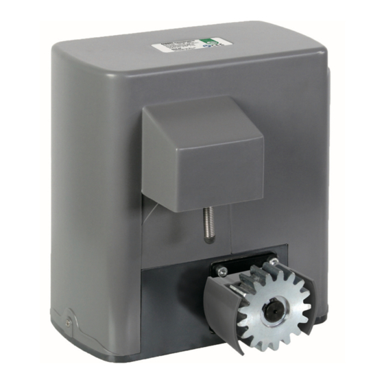
- Page 1 DE FR EN ES chiebetorantrieb ‘ écaniSMe d ouverture pour portail couliSSant liding gate operator bridor de verjaS correderaS Stan01 ’ riginal edienungSanleitung ode d eMploi original riginal inStruction Manual anual de inStruccioneS iebe undin lieber unde danke, dass Sie sich für unser Produkt entschieden haben.
-
Page 2: Sicherheitshinweise
DE FR EN ES icherheitShinweiSe Stellen Sie sicher, dass die Stromversorgung des Schiebetorantriebs (AC220-240V) mit der zu benutzenden Steckdose übereinstimmt. • Lassen Sie Kinder nicht mit festen Bedienelementen spielen. Bewahren Sie Fernbedienungen außerhalb der Reichweite von Kindern auf. • Fernbedienung läuft über Ein-Knopf-Bedienung, was bedeutet, dass es einen Knopf für die Funktionen AN, STOP und AUS gibt. - Page 3 DE FR EN ES eileliSte 1× B 2× 4× D 2× 1× F 1× 1× H 2× 4× J 12× 4× L 8× 1×...
-
Page 4: Montage
DE FR EN ES echniSche aten Spannung 220-240 V~, 50 Hz Motordrehzahl 55 U/min Leistung des Motors 180 W Bedienungsabstand der Fernbedienung 30 m (Frequenz: 433,92 mHz) Modus der Fernbedienung Einzelner Knopf Höhe der Ausgangswelle 48,5 mm Max. Gewicht des Tores 600 kg Ausgangsdrehmoment 16 Nm... - Page 5 DE FR EN ES 1. Vorbereitung des Tores Stellen Sie sicher, dass das Tor korrekt installiert ist und sich problemlos öffnen und schließen lässt, bevor Sie den Torantrieb anbringen. Das Tor muss eben ausgerichtet und frei beweglich sein. Stromleitung Benutzen Sie PVC Leitungen für Niederspannungskabel und Kontrolldrähte um das Kabel zu schützen.
-
Page 6: Installation Des Torantriebs
DE FR EN ES 2. Installation des Torantriebs • Um Stabilität zu gewährleisten, benötigt man für die Basis des Torantriebs einen Betonblock. Dieser sollte ca. die Maße 450mm x 300mm x 200mm (LxBxH) aufweisen um ausreichend Gewicht und Struktur zu haben, sodass die Konstruktion stabil ist. •... -
Page 7: Montage Der Schiene
DE FR EN ES 3. Montage der Schiene Schweißpunkt • Jedes Schienenelement hat drei Löcher, in denen jeweils ein Schrauben-Set befestigt wird (s. Abb. 4 ). • Legen Sie den ersten Teil der Schiene auf das Zahnrad und schweißen Sie die erste Mutter an das Tor (s. -
Page 8: Montage Des Infrarotsensors
DE FR EN ES • Bewegen Sie das Tor elektrisch und passen Sie die Blockierung an die von Ihnen gewünschte Position (Öffnen und Schließen) an. Schraube M6x20 (3) Abb.7 5.Montage des Infrarotsensors Der Infrarotsensor stellt während des Öffnens und Schließens Bewegungen am Tor fest. Sobald der Infrarotstrahl durchbrochen wird, wird der Torantrieb die Richtung wechseln. - Page 9 DE FR EN ES abel nSchlüSSe Achtung: Stellen Sie sicher, dass der Strom abgestellt ist, bevor Sie an den Kabelanschlüssen arbeiten. Entfernen Sie die Abdeckung des Antriebs und öffnen Sie den Steuerkasten. Fernbedienung DIP-Schalter: 1: Ein-/Dreiknopfschalter Vorwarnleuchte 2/3: Verschluss-zeiten Kondensator Richtung Toröffnung Motor...
- Page 10 DE FR EN ES 1. Anschluss der Stromeinspeisung Stromeinspeisung (X1): L (Live), N (neutral) (AC220V) Der Schiebetorantrieb muss geerdet sein. Der Erdleitungsanschluss befindet sich auf der Bodenplatte. 2. Anschluss des Infrarotsensors Verbinden Sie den Infrarotsensor "Empfänger" mit dem Anschluss 24VDC, GND und I.R. im Terminal X5 (s.
- Page 11 DE FR EN ES 6. Motor und Kondensator Die folgende Abb. 13 zeigt die Verbindungen zwischen Kondensator und Steuerkasten sowie Motor und Steuerkasten. Diese Verbindungen sind im Torantrieb bereits vorhanden. V-com Abb.13 U-Vorwärts Kondensator Motor W-Rückwärts PE-Schutzleiter Steuerkasten Terminal X3 Terminal X2 inStellung der autoMatiSchen chlieSSfunKtion...
-
Page 12: M Anuelle B Edienung
DE FR EN ES inrichten der ernbedienung Abb.14 Öffnen Sie den Steuerkasten und drücken Sie „AN1“ (s. Abb. 10), Knopf 1 das „LED2“-Lämpchen leuchtet auf. Wenn es wieder aus geht, drücken Sie jenen Knopf auf der Fernbedienung, den Sie aktivieren Knopf 2 möchten, das „LED2“-Lämpchen leuchtet für 2 Sekunden auf. - Page 13 DE FR EN ES törungSbeSeitigung Problem Möglicher Grund Lösungen Tor lässt sich nicht öffnen oder Stromzufuhr ist Stellen Sie die Stromzufuhr schließen unterbrochen LED Display leuchtet nicht Sicherung ist Ersetzen Sie die Sicherung durchgebrannt Tor kann geöffnet, aber nicht Infrarotstrahl ist durch- Entfernen Sie die Störung geschlossen werden brochen/gestört...
- Page 14 DE FR EN ES Optierung durch die öffentlich-rechtlichen Entsorgungsträger zum Zwecke der Vorberei-tung zur Wiederverwendung von anderen Altgeräten separiert werden, um diese für die Wiederverwendung vorzubereiten. Anhand des Symbols nach Anlage 3 zum ElektroG können Besitzer Altgeräte erkennen, die getrennt vom unsortierten Siedlungsabfall zu erfassen sind.
- Page 15 Dokumentation: JAGO AG Ingersheimer Str.12, D-70499 Stuttgart Beschreibung des elektrischen Betriebsmittels: Funktion: Schiebetorantrieb Typ/Modell: STAN01 Handelsmarke: Jago Spannung: 220-240 V ~, 50 Hz Es wird die Übereinstimmung mit den weiteren, ebenfalls für das Produkt geltenden Richtlinien / Bestim- mungen erklärt: •...
-
Page 16: Instructions De Sécurité
DE FR EN ES nStructionS de Sécurité Assurez-vous que l´alimentation électrique du mécanisme d´ouverture du portail coulissant (AC220-240V) correspond à la prise de courant utilisée. • Ne laissez pas les enfants jouer avec le contrôler fixe. Tenir la télécommande hors de portée des enfants. -
Page 17: Liste Des Pièces
DE FR EN ES iSte deS pièceS 1× B 2× 4× D 2× 1× F 1× 1× H 2× 4× J 12× 4× L 8× 1×... -
Page 18: Données Techniques
DE FR EN ES onnéeS techniqueS Tension 220-240 V~, 50 Hz Nombre du tour du moteur 55 U/min Puissance du moteur 180 W Distance de commande de la télécommande 30 m (Fréquence : 433,92 mHz) Type de télécommande Bouton unique Hauteur de l´onde initiale 48,5 mm Poids maximal du portail... -
Page 19: Préparation Du Portail
DE FR EN ES 1. Préparation du portail Avant de positionner le mécanisme du portail, assurez-vous que le portail est correctement installé et qu´il s´ouvre et se ferme sans difficulté. Le portail doit être positionné à plat et être mobile sans entrave. -
Page 20: Installation Du Mécanisme Du Portail
DE FR EN ES Installation du mécanisme du portail • Afin d´assurer la stabilité, on a besoin pour la base du mécanisme du portail d´un bloc de béton. Celui-ci devrait présenter des mesures 450 mm x 300 mm x 200 mm (LxBxH) afin d´avoir un poids et une structure suffisante pour que la construction soit stable. -
Page 21: Montage De La Barre
DE FR EN ES 3. Montage de la barre Schweißpunkt • Chaque élément de la barre a trois trous, un vis du set (J) doit être vissé dans chacun d´entre eux. (voir schéma 4) • Posez la première pièce de la barre sur la roue dentée et soudez le premier écrou au portail. -
Page 22: Montage Du Capteur Infrarouge
DE FR EN ES • Bougez le portail électriquement et ajustez le blocage sur la position souhaitée (ouvert ou fermée). Schéma 7 M6x20 (3) 5.Montage du capteur infrarouge Le capteur infrarouge détecte tout mouvement près du portail pendant l´ouverture et la fermeture. Aussitôt que le faisceau infrarouge est interrompu, le mécanisme du portail changera de direction. - Page 23 DE FR EN ES rancheMent de câbleS Attention : Assurez-vous que le courant est éteint avant de travailler sur les branchements de câbles. Retirez le couvercle du mécanisme et ouvrez la boite de commande. télécommande interrupteur DIP: 1: un-/trois bouton lumière interrupteur d´avertissement...
-
Page 24: Branchement De L'alimentation Électrique
DE FR EN ES 1. Branchement de l´alimentation électrique Alimentation électrique (X1): L (Live), N (neutral) (AC220V) Le mécanisme d‘ouverture pour portail coulissant doit être mis à la terre. La prise de terre se trouve sur la plaque de fond. 2. -
Page 25: Moteur Et Condensateur
DE FR EN ES 6. Moteur et condensateur Le schéma 13 suivant montre les liaisons entre le condensateur et la boite de commande ainsi qu´entre le moteur et la boite de commande. Ces liaisons sont existante dans le mécanisme du portail. -
Page 26: Réglage De La Télécommande
DE FR EN ES églage de la télécoMMande Schéma 14 Ouvrez la boite de commande et appuyez sur « marche 1 » (voir bouton 1 le schéma 10), la lampe « LED2 » s´allume. Lorsqu´elle s´éteint appuyez chaque bouton de la télécommande que vous souhaitez bouton 2 activer, la lampe «... -
Page 27: Résolution De Problème
DE FR EN ES éSolution de problèMe Problème Cause possible Solutions Le portail ne se ferme et ne Le courant électrique ne Remettez le courant passe pas s´ouvre pas Remplacez le fusible L´écran LED ne s´allume pas Le fusible est grillé Le portail peut s´ouvrir mais Le faisceau infrarouge est Eloigné... - Page 28 Ingersheimer Str. 12, D-70499 Stuttgart, Allemagne Description du matériel électrique : Fonction : Mécanisme d ́ o uverture pour portail coulissant Type / Modèle : STAN01 Marque du distributeur : Jago Tension : 220-240 V ~, 50 Hz La conformité avec les directives / dispositions suivantes également applicables pour ce produit est décla- rée :...
-
Page 29: Safety Instructions
DE FR EN ES afety inStructionS Make sure that the power supply (AC220-240 V) of the gate operator matches the electrical outlet you are using. • Do not allow children to play with the fixed controls. Keep the remote controls away from children. -
Page 30: Parts List
DE FR EN ES artS liSt 1× B 2× 4× D 2× 1× F 1× 1× H 2× 4× J 12× 4× L 8× 1×... -
Page 31: Technical Data
DE FR EN ES echnical data Voltage 220-240 V~, 50 Hz Engine speed 55 rpm Engine output 180 W Remote control operating distance 30 m (Frequency: 433.92 mHz) Remote control mode Single button Output shaft height 48.5 mm Max. gate weight 600 kg Output torque 16 Nm... - Page 32 DE FR EN ES 1. Preparation of the gate Make sure that the gate is properly installed and slides smoothly before installing the gate operator. The gate must be level and move freely. Electric cable In order to protect the cable, use PVC conduits for low voltage power cables and control wires.
- Page 33 DE FR EN ES 2. Installation of the gate operator • The base unit of the gate operator requires a concrete pad in order to maintain proper stability. The concrete pad should be of the dimensions (approximately) 450 mm x 300 mm x 200 mm (LxWxH) in order to provide adequate weight and structure to ensure a sturdy construction.
- Page 34 DE FR EN ES 3. Installation of the rail Welding spot • Each rail element has three holes. Attach one set of screws (J) to each hole (see Fig. • Lay the first piece of the rail on the gear and weld the first nut on the gate (see Fig.
- Page 35 DE FR EN ES • Move the gate electrically and adjust the block to the desired position (opening and closing). Screw M6x20 (3) Fig. 7 5. Installation of the infrared sensor The infrared sensor is used to check for any movement around the gate when opening and closing. If the infrared ray is interrupted, the gate operator will immediately reverse and run in the other direction.
-
Page 36: W Ire Connection
DE FR EN ES ire connection Warning: Make sure that the power is off before making any electrical connections. Remove the cover of operator and open the control board. Remote control DIP switch: Single-/Three Caution button switch light 2/3: Automatic closing time Capacitor Opening... - Page 37 DE FR EN ES 1. Power input connection Power input (X1): L (live), N (neutral) (AC220 V) The gate operator must be grounded. You will find the earth connector is located on the base plate. 2. Infrared sensor connection Then connect the infrared sensor receiver to the knot 24VDC, GND and I.R.
- Page 38 DE FR EN ES 6. Engine and capacitor The following Fig. 13 shows the connection between the capacitor and the control board as well as the connection between the engine and the control board. The connections have been done in the gate operator.
-
Page 39: S Etting The Remote Control
DE FR EN ES etting the reMote control Fig. 14 Open the control box and press the button ‘AN1’ (see Fig. 10), the Button 1 ‘LED2’ will be on and then turn off, and then press the remote control button which you want to use, the ‘LED2’ will turn on for Button 2 about 2 seconds and then turn off again. -
Page 40: Troubleshooting
DE FR EN ES roubleShooting Problem Possible causes Solutions The door fails to open and The power is OFF. Make sure that power is close. The fuse is blown. The LED display does not light Replace the fuse. The door can be opened but The infrared beam is Remove obstructions. -
Page 41: Ec Declaration Of Conformity
JAGO AG Ingersheimer Str. 12, D-70499 Stuttgart, Germany Description of the electrical equipment: Function: Sliding Gate Operator Machine type: STAN01 Trademark: Jago Voltage: 220-240 V ~, 50 Hz This product complies with the following valid guidelines/regulations: •... -
Page 42: Instrucciones De Seguridad
DE FR EN ES nStruccioneS eguridad Asegúrese de que la fuente de alimentación (AC 220-240 V) del abridor sea compatible con la toma de corriente usada. • No deje que los niños jueguen con controles fijos. Guarde los controles remotos lejos del alcance de niños. - Page 43 DE FR EN ES iSta iezaS 1× B 2× 4× D 2× 1× F 1× 1× H 2× 4× J 12× 4× L 8× 1×...
- Page 44 DE FR EN ES nforMación écnica Voltaje 220-240 V~, 50 Hz Velocidad del motor 55 rpm Potencia del motor 180 W Alcance (control remoto) 30 m (frecuencia: 433,92 mHz) Modo de funcionamiento (control remoto) un solo botón Altura de la onda de salida 48.5 mm Máx.
- Page 45 DE FR EN ES 1. Preparativos Asegúrese de que la verja esté instalada correctamente y que deslice suavemente antes de instalar el mecanismo de apertura. La verja debe estar nivelada y debe mover libremente. El cable de alimentación Para proteger el cable, utilice conductos PVC para cables de baja tensión y cables de control.
- Page 46 DE FR EN ES 2. Instalación del abridor • Para instalar la base del abridor se requiere una losa de hormigón para proporcionar la estabilidad necesaria. Las dimensiones aproximadas de la losa de hormigón deben ser aprox. 450 mm x 300 mm x 200 mm (L x An x Alt) para que se proporcione un peso y una estructura adecuada para asegurar una estructura robusta.
- Page 47 DE FR EN ES 3. Instalación del riel de engranaje Punto de soldadura • Cada elemento del riel tiene 3 agujeros. Inserte los tornillos (J) en cada agujero (ver imagen 4). • Ponga la primera pieza del riel en la rueda dentada y solda la primera tuerca en la verja (imagen 5).
- Page 48 DE FR EN ES • Mueva la verja eléctricamente y ajuste el bloqueo a una posición deseada (apertura y cierre). T o r n i l l o M6x20 (3) imagen 7 5. Instalación del sensor infrarrojo El sensor infrarrojo se usa para verificar si hay algún movimiento cerca de la verja cuando se abren o cierran.
- Page 49 DE FR EN ES onexión ableS Advertencia: Asegúrese de que la alimentación eléctrica esté apagada antes de conectar los cables. Retire la cubierta del abridor y abra el panel de control. Control remoto Interruptor DIP: 1. Interruptor de un solo botón/Interruptor advertencia de 3 botones 2/3: Tiempo de cierre...
-
Page 50: Conexión De La Fuente De Alimentación
DE FR EN ES 1. Conexión de la fuente de alimentación Potencia (X1): L (vivo), N (neutro) (AC 220 V) El abridor debe estar conectado a tierra. El conector a tierra está ubicado en la placa de base. 2. Conexión del sensor infrarrojo Inserte el receptor del sensor infrarrojo en el enchufe 24VDC, GND y I.R. - Page 51 DE FR EN ES 6. Motor y condensador En la imagen 13 se muestra la conexión entre el condensador y el panel de control y la conexión entre el motor y el panel de control. Estas conexiones están dentro del mecanismo de apertura. Imagen 13 V-com Condensador...
- Page 52 DE FR EN ES juSte ontrol eMoto Imagen 14 Abra la caja de control y presione el botón “AN1” (ver imagen Botón 1 10); apague el “LED2” y luego pulse el botón adecuado del control remoto.“LED2” se encenderá en aprox. 2 segundos y se apagará Botón 2 nuevamente.
-
Page 53: Protección Del Medio Ambiente
DE FR EN ES eSolución robleMaS Problema Causa posible Soluciones La verja no se puede abrir o La alimentación eléctrica Asegúrese cerrar. está desconectada. alimentación esté La pantalla LED no se ilumina. encendida. El fusible está quemado. Sustituya el fusible. La verja se puede abrir pero El rayo de luz infrarrojo Elimine las... -
Page 54: Ce - D Eclaración De Conformidad
Goran Jakovac documentación técnica: JAGO AG Ingersheimer Str. 12, D-70499 Stuttgart, Alemania Descripción del material eléctrico: Producto: Abridor de verja corredera Modelo: STAN01 Marca: Jago Voltaje: 220-240 V ~, 50 Hz Conforme a las siguientes regulaciones/disposiciones en vigor: • Directiva 2006/42/CE sobre maquinaria •...