Télécharger Imprimer la page

Publicité

Les langues disponibles

Les langues disponibles

Liens rapides

BE12
BE12 - (AS06260)
Apparecchiatura elettronica
ISTRUZIONI PER L'INSTALLAZIONE
Electronic control unit
INSTRUCTIONS FOR INSTALLATION
Platine électronique
INSTRUCTIONS POUR L'INSTALLATION
Equipo electrónico
INSTRUCCIONES PARA LA INSTALACIÓN
IT
UK
FR
ES

Publicité

loading

Sommaire des Matières pour GiBiDi BE12

  • Page 1 BE12 BE12 - (AS06260) Apparecchiatura elettronica ISTRUZIONI PER L’INSTALLAZIONE Electronic control unit INSTRUCTIONS FOR INSTALLATION Platine électronique INSTRUCTIONS POUR L’INSTALLATION Equipo electrónico INSTRUCCIONES PARA LA INSTALACIÓN...
  • Page 2 • Programmazione della richiusura automatica e del tempo di pausa tramite dip switch. • Predisposizione per uso con batterie tampone. • Soft-Start e Soft-Stop per limitare gli shock meccanici. Grazie per avere scelto GIBIDI. LEGGERE ATTENTAMENTE QUESTO MANUALE PRIMA DI PROCEDERE ALL’INSTALLAZIONE. AVVERTENZE: Questo prodotto è...
  • Page 3 BE12 3 - AVVERTENZE PER L’INSTALLAZIONE • Prima di procedere con l’installazione bisogna predisporre a monte dell’impianto un interruttore magneto termico e differenziale con portata massima 10A. L’interruttore deve garantire una separazione omnipolare dei contatti, con distanza di apertura di almeno 3 mm.
  • Page 4 BE12 5 - COLLEGAMENTI ELETTRICI: FASTON FASTON Descrizione 0 Vac da trasformatore 12 Vac da trasformatore 6 - COLLEGAMENTI ELETTRICI: MORSETTIERE Morsetto Posizione Segnale Descrizione Motore 1+ Motore 1- Motore 2+ Motore 2- + Alimentazione elettroserratura 12V. - Alimentazione elettroserratura 12V.
  • Page 5 BE12 7 - FUSIBILI DI PROTEZIONE Posizione Valore Tipo Descrizione Protegge l’alimentazione batteria 12V. Protegge gli accessori esterni, l’elettroserratura e il lampeggiante 3,15A Protegge la scheda elettronica. Protegge il trasformatore. 8 - LED DI SEGNALAZIONE Posizione Colore Segnale Descrizione Si accende quando viene attivato il comando START dalla morsettiera o dalla ricevente.
  • Page 6 BE12 9 - DIP SWITCH DIP1 Le impostazioni vengono memorizzate durante la fase di riposo (cancello chiuso). Le impostazioni di DEFAULT sono evidenziate con lo sfondo della casella in grigio Funzione Stato Descrizione Funzionamento in risposta al comando di START : →...
  • Page 7 BE12 9 - DIP SWITCH DIP1 Le impostazioni vengono memorizzate durante la fase di riposo (cancello chiuso). Le impostazioni di DEFAULT sono evidenziate con lo sfondo della casella in grigio Funzione Stato Descrizione Abilita il prelampeggio di 3 secondi prima dell’attivazione del motore in apertura e chiusura.
  • Page 8 BE12 10 - DIP SWITCH DIP2 Le impostazioni vengono memorizzate durante la fase di riposo (cancello chiuso). Le impostazioni di DEFAULT sono evidenziate con lo sfondo della casella in grigio Funzione Stato Descrizione INUTILIZZATO INUTILIZZATO Utilizzo delle uscite M2-7 e M2-8 come LUCE SPIA, sempre accesa fissa con SPIA cancello aperto.
  • Page 9 BE12 11 - JUMPER SW4 Le impostazioni vengono memorizzate durante la fase di riposo (cancello chiuso). Le impostazioni di DEFAULT sono evidenziate con lo sfondo della casella in grigio JUMPER Funzione Stato Descrizione All'ingresso STOP/COSTA (21) sono collegati dispositivi di tipo N.C.
  • Page 10 BE12 13 - GESTIONE RICEVENTE RADIO A BORDO Memorizzazione nuovo trasmettitore: 1 - Premere e rilasciare il pulsante Learn. 2 - Il led L6 si accenderà 3 - Premere il tasto 1 del radiocomando da memorizzare per 2 secondi. 4 - Il nuovo radiocomando è memorizzato.
  • Page 11 BE12 Movimenti eseguiti durante l’apprendimento con 2 motori: • Motore 1 apre fino ad incontrare le battute meccaniche. • Motore 2 apre fino ad incontrare le battute meccaniche. • Pausa di 5 secondi. • Motore 2 chiude fino ad incontrare le battute meccaniche.
  • Page 12 BE12 17 - RISOLUZIONE PROBLEMI Ÿ Verificare che L3, L4, L5 siano spenti, se non lo fossero, verificare i dispositivi connessi ai morsetti 19-20-21. Il cancello non si muove in seguito ad un Ÿ Controllare i fusibili. comando di START Ÿ...
  • Page 13 GI.BI.DI. S.r.l. Via Abetone Brennero, 177/B, 46025 Poggio Rusco (MN) ITALY dichiara che i prodotti: APPARECCHIATURA ELETTRONICA BE12 sono conformi alle seguenti Direttive CEE: Direttiva LVD 2006/95/CE e successive modifiche; • • Direttiva EMC 2004/108/CE e successive modifiche; e che sono state applicate le seguenti norme armonizzate: EN60335-1, •...
  • Page 14 • Programming of automatic closing and pause time via DIP switch. • Provision for use with buffer batteries. • Soft-Start and Soft-Stop to limit mechanical shock. Thank you for choosing GIBIDI. READ CAREFULLY THESE INSTRUCTIONS BEFORE PROCEEDING WITH INSTALLATION. WARNINGS: This product has been tested by GI.BI.DI.
  • Page 15 BE12 3 - INSTALLATION WARNINGS • Before proceeding with installation, fit a differential magnetothermal switch with a maximum capacity of 10A upstream of the system. The switch must guarantee omnipolar separation of the contacts with an opening distance of at least 3mm.
  • Page 16 BE12 5 - ELECTRICAL CONNECTIONS: CONNECTORS FASTON Description 0 VAC from transformer 12 VAC from transformer 6 - ELECTRICAL CONNECTIONS: TERMINAL BOARDS Terminal Position Signal Description Motor 1+ Motor 1- Motor 2+ Motor 2- Electric lock power supply - Electric lock power supply 12V + FLASHLIGHT power supply 12 VDC MAX 10W.
  • Page 17 BE12 7 - PROTECTION FUSES Position Value Type Description Protects battery power circuit. Protects external accessories, electric lock and flashing light. 3,15A Protects the circuit board. Protects the transformer. 8 - WARNING LEDs Position Colour Signal Description Comes on when the START control is activated from the terminal board or the receiver.
  • Page 18 BE12 9 - DIP SWITCH DIP1 The settings are stored during the rest phase (gate closed). The default settings are highlighted in the boxes with grey background. Function Status Description Operation in response to the START command: → ŸGate closed OPENS →...
  • Page 19 BE12 9 - DIP SWITCH DIP1 The settings are stored during the rest phase (gate closed). The default settings are highlighted in the boxes with grey background. Function Status Description Enables pre-flashing of 3 seconds before motor activation during opening and closing.
  • Page 20 BE12 10 - DIP SWITCH DIP2 The settings are stored during the rest phase (gate closed). The default settings are highlighted in the boxes with grey background. Function Status Description UNUSED UNUSED Terminal M2_7 and M2_8 work as WARNING LIGHT.
  • Page 21 BE12 11 - JUMPER SW4 The settings are stored during the rest phase (gate closed). The default settings are highlighted in the boxes with grey background. JUMPER Function Status Description N.C. devices are connected to STOP/EDGE (21) input FUNCTIONING TERMINAL 21 8,2KOhm (8K2) resistive devices are connected to STOP/EDGE (21) input.
  • Page 22 BE12 13 - ONBOARD RADIO RECEIVER CONTROL Storing a new transmitter in memory: 1 - Press and release Learn button. 2 - Led L6 will come on. 3 - Press button 1 of the transmitter to be stored for 2 seconds.
  • Page 23 BE12 Movements during learning with 2 motors: • Motor 1 opens until meeting the mechanical end-stops. • Motor 2 opens until meeting the mechanical end-stops . • 5 seconds pause. • Motor 2 closes until meeting the mechanical end-stops. • Motor 1 closes until meeting the mechanical end-stops.
  • Page 24 BE12 17 - TROUBLESHOOTING Ÿ Check that L3, L4 and L5 are off; if not, check the devices connected to terminals 19-20-21. The gate does not move after a START Ÿ Check fuses. command. Ÿ Check that the battery voltage is not below 11Vdc.
  • Page 25 S.r.l. Via Abetone Brennero, 177/B, 46025 Poggio Rusco (MN) ITALY eclares that the products ELECTRONIC CONTROL UNIT BE12 are in conformity to the following CEE Directives Directive LVD 2006/95/CE and subsequent amendments; • • Directive EMC 2004/108/CE and subsequent amendments;...
  • Page 26 
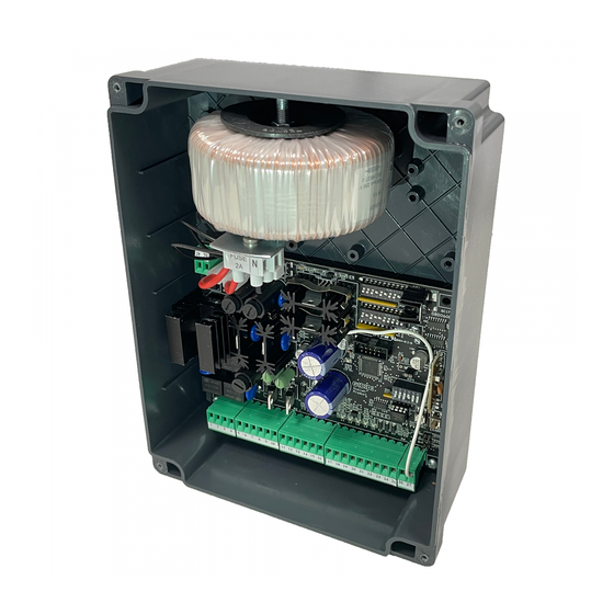
BE12 1 - CARACTERISTIQUES TECHNIQUES Platine BE12 / AS06260 Platine électronique pour l’automation d’un Type portail battant avec double porte et moteurs en 12Vdc Alimentation 230 Vac monophasé 50/60 Hz N° moteurs Alimentation moteur 12 Vdc Clignoteur 12 Vdc 10W max...
  • Page 27 BE12 3 - INSTRUCTIONS POUR L’INSTALLATION • Avant d’effectuer l’installation, il faut prévoir en amont de la même un interrupteur magnétique thermique et différentiel avec capacité maxi 10A. L’interrupteur doit assurer une séparation omnipolaire des contacts, avec distance d’ouverture d’au moins 3 mm.
  • Page 28 BE12 5 - BRANCHEMENTS ELECTRIQUES: FASTON FASTON Description 0 Vac de transformateur 12 Vac de transformateur 6 - BRANCHEMENTS ELECTRIQUES: BORNIERS Borne Position Signal Description Moteur 1+ Moteur 1- Moteur 2+ Moteur 2- + Alimentation serrure électrique 12V. - Alimentation serrure électrique 12V.
  • Page 29 BE12 7 - FUSIBLES DE PROTECTION Position Valeur Type Description Protection alimentation batterie 12V. Protection accessoires extérieurs, serrure électrique et clignoteur 3,15A Protection platine électronique. Protection transformateur. 8 - LED DE SIGNALISATION Position Couleur Signal Description S’allume quand on active la commande START du bornier ou du récepteur.
  • Page 30 BE12 9 - DIP SWITCH DIP1 Les positions sont mémorisées pendant la phase de repos (portail fermé). Les positions par DEFAUT sont indiquées dans la case grise Fonction Etat Description Fonctionnement en réponse à la commande de START : →...
  • Page 31 BE12 9 - DIP SWITCH DIP1 Les positions sont mémorisées pendant la phase de repos (portail fermé). Les positions par DEFAUT sont indiquées dans la case grise Fonction Etat Description Habilite le pré-clignotement de 3 s avant l’activation du moteur en ouverture et fermeture.
  • Page 32 BE12 10 - DIP SWITCH DIP2 Les positions sont mémorisées pendant la phase de repos (portail ouvert). Les positions par DEFAUT sont indiquées avec la case grise Fonction Etat Description PAS UTILISE PAS UTILISE Utilisation des sorties M2-7 et M2-8 comme LAMPE TEMOIN, toujours allumée fixe LAMPE TEMOIN avec portail ouvert.
  • Page 33 BE12 11 - JUMPER SW4 Les positions sont mémorisées pendant la phase de repos (portail ouvert). Les positions par DEFAUT sont indiquées avec la case grise JUMPER Fonction Etat Description Les dispositifs N.C. sont connectées à l'entrée STOP/BORD SENSIBLE (21)
  • Page 34 BE12 13 - GESTION RECEPTEUR RADIO A BORD Mémoriser un nouvel émetteur: 1 - Appuyer sur la touche Learn et la relâcher. 2 - Le led L6 s’allumera 3 - Appuyer sur la touche 1 de l’émetteur à mémoriser pendant 2 s.
  • Page 35 BE12 Mouvements faits pendant l’apprentissage avec 2 moteurs: • Moteur 1 ouvre jusqu’à rencontrer les arrêts mécaniques. • Moteur 2 ouvre jusqu’à rencontrer les arrêts mécaniques. • Pause de 5 s • Moteur 2 ferme jusqu’à rencontrer les arrêts mécaniques.
  • Page 36 BE12 17 - RESOLUTION DE PROBLEMES ŸVérifier que L3, L4, L5 soient éteints; en cas contraire, vérifier les dispositifs connectés aux bornes 19-20-21. Le portail ne fonctionne pas après une Ÿ Contrôler les fusibles. commande de START Ÿ Contrôler que le voltage des batteries ne soit pas inférieur à 11Vdc.
  • Page 37 BE12 Déclaration de conformité CE Le constructeur GI.BI.DI. S.r.l. Via Abetone Brennero, 177/B, 46025 Poggio Rusco (MN) ITALY éclare que le produit ci-dessous APPAREILLAGE ÉLECTRONIQUE BE12 est conforme aux Directives CEE suivantes Directive LVD 2006/95/CE et modifications successives; • • Directive EMC 2004/108/CE et modifications successives;...
  • Page 38 • Predisposición para uso con baterías-tampón. • Soft-Start y Soft-Stop para limitar los choques mecánicos. Gracias por haber elegido GIBIDI. LEER ATENTAMENTE ESTE MANUAL ANTES DE PROCEDER CON LA INSTALACIÓN. ADVERTENCIAS: Este producto ha sido ensayado en GI.BI.DI. verificando la perfecta correspondencia de las características a las directivas vigentes.
  • Page 39 BE12 3 - ADVERTENCIAS PARA LA INSTALACION • Antes de proceder a la instalación, hay que preparar aguas arriba de la instalación un interruptor magneto- térmico y diferencial con capacidad máxima de 10A. El interruptor debe garantizar una separación omnipolar de los contactos, con distancia de apertura mínima de 3 mm.
  • Page 40 BE12 5 - CONEXIONES ELECTRICAS: FASTON FASTON Descripción 0 Vac desde transformador 12 Vac desde transformador 6 - CONEXIONES ELECTRICAS: TABLEROS DE BORNES Borne Posición Señal Descripción Motor 1+ Motor 1- Motor 2+ Motor 2- + Alimentación electrocerradura 12V. - Alimentación electrocerradura 12V.
  • Page 41 BE12 7 - FUSIBLES DE PROTECCION Posición Valor Tipo Descripción Protege la alimentación batería 12V. Protege los accesorios externos, la electrocerradura y el indicador 3,15A Protege la ficha electrónica. Protege el transformador. 8 - LED DE SEÑALIZACION Posición Color Señal Descripción...
  • Page 42 BE12 9 - DIP SWITCH DIP1 Las posiciones son memorizadas durante la fase de reposo (cancela cerrada). Las posiciones por DEFECTO son evidenciadas por la casilla gris Función Estado Descripción Funcionamiento en respuesta al mando de START : → Ÿ Cancela cerrada ABRE →...
  • Page 43 BE12 9 - DIP SWITCH DIP1 Las posiciones son memorizadas durante la fase de reposo (cancela cerrada). Las posiciones por DEFECTO son evidenciadas por la casilla gris Función Estado Descripción Habilita el pre-destello de 3 segundos antes de la activación del motor en apertura y cierre.
  • Page 44 BE12 10 - DIP SWITCH DIP2 Las posiciones son memorizadas durante la fase de reposo (cancela cerrada). Las posiciones por DEFECTO son evidenciadas por la casilla gris Función Estado Descripción NO UTILIZADO NO UTILIZADO Uso de las salidas M2-7 y M2-8 como LUZ TESTIGO, siempre encendida fija con LUZ TESTIGO cancela abierta.
  • Page 45 BE12 11 - JUMPER SW4 Las posiciones son memorizadas durante la fase de reposo (cancela cerrada). Las posiciones por DEFECTO son evidenciadas por la casilla gris JUMPER Función Estado Descripción En la entrada STOP/BANDA SENSIBLE (21) son conectados dispositivos de tipo N.C.
  • Page 46 BE12 13 - GESTION RECEPTOR RADIO A BORDO Memorización nuevo transmisor: 1 - Apretar y soltar la tecla Learn. 2 - El led L6 se encenderá 3 - Apretar la tecla 1 del transmisor que se debe memorizar por 2 segundos.
  • Page 47 BE12 Movimientos hechos durante el aprendizaje con 2 motores: • Motor 1 abre hasta encontrar los topes mecánicos. • Motor 2 abre hasta encontrar los topes mecánicos. • Pausa de 5 segundos • Motor 2 cierra hasta encontrar los topes mecánicos.
  • Page 48 BE12 17 - SOLUCION DE PROBLEMAS ŸVerificar que L3, L4, L5 sean apagados; en caso contrario, verificar los dispositivos conectados a los bornes 19-20-21. Ÿ La cancela no se mueve después de un Controlar los fusibles. mando de START Ÿ...
  • Page 49 BE12 Declaración de conformidad CE El fabricante GI.BI.DI. S.r.l. Via Abetone Brennero, 177/B, 46025 Poggio Rusco (MN) ITALY eclara que los productos: EQUIPO ELECTRÓNICO BE12 on conformes con las siguientes Directivas CEE Directiva LVD 2006/95/CE y sucesivas modificaciones; • • Directiva EMC 2004/108/CE y sucesivas modificaciones;...
  • Page 50 BE12 NOTE / NOTES / NOTES / NOTAS...
  • Page 51 BE12 NOTE / NOTES / NOTES / NOTAS...
  • Page 52 GI.BI.DI. S.r.l. Via Abetone Brennero, 177/B 46025 Poggio Rusco (MN) - ITALY Tel. +39.0386.52.20.11 Fax +39.0386.52.20.31 E-mail: info@gibidi.com Numero Verde: 800.290156 w w w . g i b i d i . c o m...

Ce manuel est également adapté pour:

As06260