Publicité

Les langues disponibles
  • FR

Les langues disponibles

Liens rapides

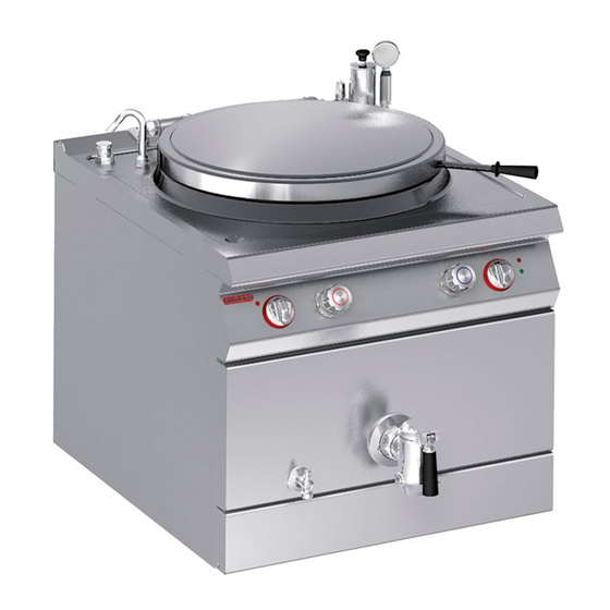
PENTOLA DIRETTA "GAS"
GAS DIRECT HEATED BOILING PAN
EINWANDIGER GASKOCHKESSEL
MARMITE CHAUFFE DIRECTE "GAZ"
MARMITA DIRECTA "GAS"
MANUALE D'USO E INSTALLAZIONE
MANUEL D'UTILISATION ET D'INSTALLATION
USE AND INSTALLATION MANUAL
BEDIEN- UND INSTALLATIONSHANDBUCH
MANUAL DE USO E INSTALACIÓN
191PD1G
191PD2G
Italiano
English
Deutsch
Français
Español
Ed. 2
01/2010
3069600
IT
GB
DE
FR
ES

Publicité

Table des Matières
loading

Sommaire des Matières pour Ndustrio 191PD1G

  • Page 1 PENTOLA DIRETTA “GAS” GAS DIRECT HEATED BOILING PAN 191PD1G EINWANDIGER GASKOCHKESSEL 191PD2G MARMITE CHAUFFE DIRECTE “GAZ” MARMITA DIRECTA “GAS” MANUALE D’USO E INSTALLAZIONE USE AND INSTALLATION MANUAL BEDIEN- UND INSTALLATIONSHANDBUCH MANUEL D’UTILISATION ET D’INSTALLATION MANUAL DE USO E INSTALACIÓN Italiano...
  • Page 3: Table Des Matières

    INDICE rif. capitoli pag. 1 INFORMAZIONI GENERALI ..........2 2 INFORMAZIONI TECNICHE ..........4 3 SICUREZZA ............... 6 PARTE 4 USO E FUNZIONAMENTO ..........7 5 MANUTENZIONI ..............9 6 GUASTI ................11 7 MOVIMENTAZIONE E INSTALLAZIONE ......12 8 REGOLAZIONI ..............19 PARTE 9 SOSTITUZIONE PARTI ...........
  • Page 4: Informazioni Generali

    INFORMAZIONI GENERALI RACCOMANDAZIONI PER IL LETTORE Per rintracciare facilmente gli argomenti specifici di parte: contiene tutte le informazioni ne- interesse, consultare l’indice analitico posto all’ini- cessarie ai destinatari omogenei, cioè tutti gli zio del manuale. operatori esperti e autorizzati a movimentare, Questo manuale è...
  • Page 5 IDENTIFICAZIONE COSTRUTTORE E APPARECCHIATURA La targhetta di identificazione raffigurata è applicata ) Potenza dichiarata (kW) direttamente sull'apparecchiatura. In essa sono ri- ) Consumo gas portati i riferimenti e tutte le indicazioni indispensa- ) Indicatore gas collaudo bili alla sicurezza di esercizio. ) Tensione (V) Targa complementare ) Frequenza (Hz)
  • Page 6: Informazioni Tecniche

    INFORMAZIONI TECNICHE DESCRIZIONE GENERALE APPARECCHIATURA La pentola diretta, d'ora innanzi definita apparec- 191PD1G (100 Lt) chiatura, è stata progettata e costruita per la prepa- 191PD2G (150 Lt) razione e cottura di alimenti nell'ambito della ristorazione professionale. In funzione delle esigenze di utilizzo, l'apparecchia- tura è...
  • Page 7 DISPOSITIVI DI SICUREZZA Anche se l'apparecchiatura è completa di tutti i di- spositivi di sicurezza, in fase di installazione e allac- ciamento essi dovranno, se necessario, essere integrati con altri in modo da rispettare le leggi vi- genti in materia. L'illustrazione indica la posizione dei dispositivi.
  • Page 8: Sicurezza

    ACCESSORI A RICHIESTA A richiesta l'apparecchiatura può essere corredata dei seguenti accessori. A)Camino alto tipo B11 (MB33) B)Camino alto tipo B11 con dispositivo di rompitiraggio antivento MT33 C)Colapasta D)Griglia di scarico E)Sifone di scarico F) Piedi di appoggio G)Kit per installazione “a ponte” (vedi pag. 14) H)Kit telaio di appoggio (vedi pag.
  • Page 9: Uso E Funzionamento

    USO E FUNZIONAMENTO RACCOMANDAZIONI PER L'USO E FUNZIONAMENTO Importante L'incidenza degli infortuni derivanti zioni principali. Attuare solo gli usi previsti dall'uso di apparecchiature dipende da dal costruttore e non manomettere nessun molti fattori che non sempre si riescono a dispositivo per ottenere prestazioni diverse prevenire e controllare.
  • Page 10 ACCENSIONE E SPEGNIMENTO BRUCIATORE Accensione 1 - Aprire il rubinetto alimentazione gas. 2 - Premere e ruotare la manopola (A) in senso an- tiorario (pos. 1) e contemporaneamente mante- nere premuto il pulsante (B) per accendere la spia pilota. Mantenere premuta la manopola per circa 15 sec per consentire l'intervento della termocoppia.
  • Page 11: Manutenzioni

    RIMOZIONE DEL CESTELLO E PRESA DEI MANICI La rimozione del cestello contenente il prodotto Si sottolinea il fatto che il Cliente ( Datore di Lavoro deve essere effettuata o da due operatori o median- ) ha l'obbligo di valutare i rischi residui per la salute te l'ausilio di apparecchi di sollevamento opportuni, e sicurezza degli operatori connessi con l'utilizzo al fine di eliminare eventuali rischi per la salute e si-...
  • Page 12 PULIZIA APPARECCHIATURA Se si considera che l'apparecchiatura è utilizzata per tamente con gli alimenti e tutte le zone limitrofe. la preparazione di prodotti alimentari per l'uomo, è necessario prestare particolare cura a tutto ciò che Importante riguarda l'igiene e mantenere costantemente pulita Non usare prodotti che contengono sostan- l'apparecchiatura e tutto l'ambiente circostante.
  • Page 13: Guasti

    CONTROLLO PRESSIONE GAS Per questa operazione procedere nel modo indicato. 1 - Chiudere il rubinetto alimentazione gas. 2 - Sfilare le manopole (A). 3 - Smontare i gruppi manopole (B). 4 - Svitare le viti (C) e smontare il cruscotto (D). 5 - Svitare la vite (E) della presa di pressione.
  • Page 14: Movimentazione E Installazione

    MOVIMENTAZIONE E INSTALLAZIONE RACCOMANDAZIONI PER LA MOVIMENTAZIONE E INSTALLAZIONE Importante Eseguire la movimentazione e l'installazio- ste operazioni dovrà, se necessario, orga- ne nel rispetto delle informazioni fornite dal nizzare “piano sicurezza” costruttore e riportate direttamente sull'im- salvaguardare l'incolumità delle persone ballo, sull'apparecchiatura e nelle istruzioni direttamente coinvolte.
  • Page 15 INSTALLAZIONE APPARECCHIATURA Tutte le fasi di installazione devono essere conside- rate sin dalla realizzazione del progetto generale. Prima di iniziare tali fasi, oltre alla definizione della zona di installazione, chi è autorizzato ad eseguire queste operazioni dovrà, se necessario, attuare un “piano di sicurezza”...
  • Page 16 2 - Prima di avvitare il rubinetto (B) al tubo di sca- rico della pentola, interporre la ghiera (C). 3 - Predisporre un idoneo sistema di drenaggio (D) sotto al rubinetto di scarico (B). IDM-39615401300.tif IDM-3960200180.tif LIVELLAMENTO Agire sui piedi di appoggio (A) per livellare l'appa- recchiatura.
  • Page 17 Per le apparecchiature in batteria sono disponibili, L) Kit telaio di appoggio a richiesta, diversi kit di allestimento: M)Kit trave di sostegno H)Kit per installazione “a ponte” IDM-39614401800.tif ALLACCIAMENTO ACQUA Per effettuare l'allacciamento, collegare il tubo di rete con il tubo di attacco dell'apparecchiatura, in- terponendo un rubinetto di intercettazione (A) per interrompere, quando necessario, l'alimentazione dell'acqua.
  • Page 18 ALLACCIAMENTO GAS Importante Chi è autorizzato ad effettuare tale opera- ti normativi e legislativi. Ad allacciamento zione deve possedere capacità ed espe- completato, prima di rendere operativa l'at- rienza acquisita e riconosciuta nel settore trezzatura, si dovrà verificare attraverso un specifico, dovrà...
  • Page 19 ALLACCIAMENTO ELETTRICO Importante L'allacciamento deve essere effettuato da Effettuare l'allacciamento dell'apparecchiatura alla personale autorizzato e qualificato, nel ri- rete di alimentazione nel modo indicato. spetto delle leggi vigenti in materia e con 1 - Installare, se non è presente, un interruttore se- l'utilizzo di materiale appropriato e prescritto.
  • Page 20 TRASFORMAZIONE ALIMENTAZIONE L'apparecchiatura è stata collaudata dal costruttore con il proprio gas di rete, segnalato dall'adesivo ap- plicato sulla targhetta di identificazione. Se il tipo di gas da allacciare è diverso da quello di collaudo, procedere nel modo indicato. 1 - Chiudere il rubinetto alimentazione gas (A). 2 - Sostituire l'ugello del bruciatore (vedi pag.
  • Page 21: Regolazioni

    REGOLAZIONI RACCOMANDAZIONI PER LE REGOLAZIONI Importante Prima di effettuare qualsiasi intervento di re, chiudere il rubinetto alimentazione gas regolazione, attivare tutti i dispositivi di si- ed impedire l'accesso a tutti i dispositivi curezza previsti e valutare la necessità di che potrebbero, se attivati, provocare con- informare adeguatamente il personale che dizioni di pericolo inatteso e di rischio per opera e quello nelle vicinanze.
  • Page 22 REGOLAZIONE ARIA PRIMARIA BRUCIATORE Per questa operazione procedere nel modo indica- 1 - Chiudere il rubinetto alimentazione gas. 2 - Aprire il portello (A). 3 - Allentare la vite di bloccaggio (B) della ghiera (C). 4 - Regolare la posizione della ghiera (C) alla di- stanza (D) riportata in tabella.
  • Page 23: Sostituzione Parti

    INGRASSAGGIO RUBINETTO GAS Per questa operazione procedere nel modo indicato. 1 - Chiudere il rubinetto alimentazione gas. 2 - Sfilare le manopole (A). 3 - Smontare i gruppi manopole (B). 4 - Svitare le viti (C) e smontare il cruscotto (D). 5 - Svitare le viti (E) ed estrarre la calotta (F).
  • Page 24 SOSTITUZIONE UGELLO SPIA PILOTA Per questa operazione procedere nel modo indi- cato. 1 - Chiudere il rubinetto alimentazione gas. 2 - Aprire il portello (A). 3 - Svitare il raccordo (B). 4 - Estrarre l'ugello (C) e sostituirlo con quello adatto al tipo di gas utilizzato (vedi tabella in fondo al manuale).
  • Page 25 CONTENTS ref. chapters page 1 GENERAL INFORMATION ..........2 2 TECHNICAL INFORMATION ..........4 3 SAFETY ................6 PART 4 USE AND OPERATION ............. 7 5 SERVICING ............... 9 6 FAULT ................11 7 HANDLING AND INSTALLATION ........12 8 ADJUSTMENTS ............... 19 PART 9 REPLACING PARTS ............
  • Page 26: General Information

    GENERAL INFORMATION INFORMATION FOR THE READER To find the specific topics of interest to you quickly, part: contains all the information neces- refer to the index at the start of the manual. sary for special categories of reader, i.e. all This manual is subdivided into two parts.
  • Page 27 IDENTIFICATION OF CONSTRUCTOR AND APPLIANCE The nameplate shown here is fitted directly to the ) Rated power (kW) ) Gas consumption appliance. It contains references and all essential ) Testing gas indicator frame information for operating safety. ) Voltage (V) Extra nameplate ) Frequency (Hz) ) Country of use...
  • Page 28: Technical Information

    TECHNICAL INFORMATION GENERAL DESCRIPTION OF APPLIANCE The direct heated boiling pan, referred to from now 191PD1G (100 Lt) on as the appliance, is designed and constructed 191PD2G (150 Lt) for preparing and cooking in water pasta and other foods in the professional catering sector.
  • Page 29 SAFETY DEVICES Although the appliance is complete with all safety devices, during installation and connection addi- tional devices must be added if necessary to com- ply with the relevant legal requirements. The illustration shows the position of the devices. A)Gas supply tap: for turning the connection to the gas supply line on and off.
  • Page 30: Safety

    OPTIONAL ACCESSORIES The appliance can be equipped with the following accessories on request. A)Type B11 (MB33) tall fume exhaust vent B)Type B11 tall fume exhaust vent with draught damp- er device MT33. C)Pasta basket D)Drain grid E)Drain siphon F) Feet G)"Bridge"...
  • Page 31: Use And Operation

    USE AND OPERATION RECOMMENDATIONS FOR USE Important The rate of accidents deriving from the use and the main functions. Use only as intend- of appliances depends on many factors ed by the constructor and never tamper which cannot always be foreseen and con- with any device to obtain performance lev- trolled.
  • Page 32 SWITCHING THE BURNER ON AND OFF Lighting 1 - Turn on the gas supply tap. 2 - Press the knob (A) and turn it anti-clockwise (pos. 1), while keeping button (B) pressed, to light the pilot light. Keep the knob pressed for about 15 sec. to prime the thermocouple.
  • Page 33: Servicing

    REMOVING THE BASKET AND USE OF THE HANDLES To avoid any health and safety risks (back injuries) Customers (Employers) are reminded of their obli- arising from the handling of the equipment, the bas- gation to assess the residual risks to the health and ket containing the product must be removed by two safety of operatives arising from the use of the ap- operatives or with the aid of suitable lifting equip-...
  • Page 34 CLEANING INSTRUCTIONS Since the appliance is used for preparing foods for Important human consumption, special care must be paid to everything relating to hygiene, and the appliance Never use products containing substances harmful or hazardous for health (solvents, and the entire surrounding environment must con- petroleum spirits, etc.).
  • Page 35: Fault

    CHECKING GAS PRESSURE To carry out this operation, proceed as follows. 1 - Turn off the gas supply tap. 2 - Pull off the knob (A). 3 - Remove the knob unit (B). 4 - Undo the screws (C) and remove the control panel (D).
  • Page 36: Handling And Installation

    HANDLING AND INSTALLATION RECOMMENDATIONS FOR HANDLING AND INSTALLATION Important When handling and installing the appliance use. If necessary, the person authorised to comply with the information provided by carry out these operations must organise a the constructor directly on the packaging, "safety plan"...
  • Page 37 INSTALLATION OF THE APPLIANCE All installation stages must be considered right from production of the general layout. Before starting these stages, as well as deciding the place of instal- lation, if necessary, the person authorised to carry out these operations must organise a "safety plan" to protect the people directly involved, and he must also ensure strict compliance with all legal require- ments, especially those relating to mobile work-...
  • Page 38 2 - Before screwing the tap (B) onto the pan's drain pipe, fit the ring nut (C). 3 - Provide a suitable drainage system (D) under- neath the drain tap (B). IDM-39615401300.tif IDM-3960200180.tif LEVELLING Adjust the floor-mounted feet (A) to level the appli- ance.
  • Page 39 A variety of optional installation kits are available for L) Supporting frame kit arranging appliances in banks: M)Supporting beam kit H)"Bridge" installation kit IDM-39614401800.tif WATER CONNECTION To make the connection, connect the mains line to the appliance's connection pipe, fitting a shut-off tap (A), to allow the water supply to be cut off when necessary.
  • Page 40 GAS CONNECTION Important Those authorised to carry out this opera- lations and legislation. Once the connec- tion must have experience acquired and tion has been made, before the appliance is certified in the specific sector, must make put into operation a general check must be the connection to the proper standards, made to ensure there are no gas leaks.
  • Page 41 ELECTRICAL CONNECTION Important The connection must be made by author- Connect the appliance to the mains electricity sup- ised, skilled personnel, in accordance with ply as follows. the relevant legal requirements, using ap- 1 - If not already present, install a circuit-breaker propriate and specified materials.
  • Page 42 CONVERSION OF GAS SUPPLY The constructor has tested the appliance with its own mains gas, identified by the sticker applied to the nameplate. If the type of gas to be connected is different from that used for testing, proceed as follows. 1 - Turn off the gas supply tap (A).
  • Page 43: Adjustments

    ADJUSTMENTS RECOMMENDATIONS FOR ADJUSTMENTS Important Before making any type of adjustment, acti- turn off the gas supply tap and prevent ac- vate all the safety devices provided and de- cess to all devices which might cause un- cide whether staff at work and those in the expected health and safety hazards if vicinity should be informed.
  • Page 44 ADJUSTING BURNER PRIMARY AIR To carry out this operation, proceed as follows. 1 - Turn off the gas supply tap. 2 - Open the hatch (A). 3 - Back off the screw (B) which secures the ring nut (C). 4 - Set the ring nut (C) at the distance (D) shown in the table.
  • Page 45: Replacing Parts

    GREASING THE GAS TAP To carry out this operation, proceed as follows. 1 - Turn off the gas supply tap. 2 - Pull off the knob (A). 3 - Remove the knob unit (B). 4 - Undo the screws (C) and remove the control panel (D).
  • Page 46 REPLACEMENT OF THE PILOT LIGHT INJECTOR To carry out this operation, proceed as follows. 1 - Turn off the gas supply tap. 2 - Open the hatch (A). 3 - Unscrew the union (B). 4 - Remove the nozzle (C) and replace it with the one suitable for the type of gas in use (see table at back of manual).
  • Page 47 INHALTSVERZEICHNIS Ref. Kapitel Seite 1 ALLGEMEINES ..............2 2 TECHNISCHE INFORMATIONEN ........4 3 SICHERHEIT ..............6 1. TEIL 4 GEBRAUCH UND BETRIEB ..........7 5 WARTUNG ................. 9 6 DEFEKTE ................. 11 7 HANDHABUNG UND INSTALLATION ......12 8 EINSTELLUNGEN ............19 2.
  • Page 48: Allgemeines

    ALLGEMEINES INFORMATIONEN FÜR DEN LESER Konsultieren Sie das Sachregister, das am Anfang 2. Teil: Diese Informationen wenden sich an eine bestimmte Zielgruppe. Sie sind für er- des Handbuchs zu finden ist, um leichter unter be- fahrene Bediener bestimmt, die für Handha- stimmten Themen von besonderem Interesse bung, Transport,...
  • Page 49 TYPENSCHILD FÜR HERSTELLER UND GERÄT Das abgebildete Typenschild wird direkt auf dem ) Angabe der Leistung (Kw) ) Gasverbrauch Gerät aufgebracht. Es enthält sämtliche Angaben ) Testgasanzeige und Hinweise, die für den sicheren Betrieb unerläs- ) Spannung (V) slich sind. ) Frequenz (Hz) Ergänzungsschild ) Leistungsaufnahme (W)
  • Page 50: Technische Informationen

    TECHNISCHE INFORMATIONEN ALLGEMEINE BESCHREIBUNG DES GERÄTS Der einwandige Kochkessel, der im Folgenden als 191PD1G (100 Lt) Gerät bezeichnet wird, wurde zum Zubereiten und 191PD2G (150 Lt) Kochen von Nudeln in Wasser in Restaurantbetrie- ben projektiert und konstruiert. Das Gerät wird bedarfsabhängig in verschiedenen Versionen hergestellt (siehe Abbildung).
  • Page 51 SICHERHEITSVORRICHTUNGEN Das Gerät wird zwar mit sämtlichen planmäßigen Sicherheitsvorrichtungen geliefert, es kann jedoch notwendig sein, während Installation und An- schluss ggf. weitere ergänzende Maßnahmen zu ergreifen, um den Anforderungen der einschlägi- gen geltenden Gesetze zu entsprechen. Die Abbildung zeigt die Anordnung der Sicherheits- vorrichtungen.
  • Page 52: Sicherheit

    OPTIONALES ZUBEHÖR Auf Wunsch kann das Gerät mit folgenden Zube- hörteilen ausgestattet werden. A)Hoher Abzugskamin Typ B11 (MB33) B)Hoher Kamin Typ B11 mit Zugunterbrecher bei Windbeeinflussung MT33 C)Abtropfsieb D)Abflussgitter E)Siphon F) Stützfüße G)Einbausatz für Brückenmontage (siehe Seite 14) H)Einbausatz für Untergestell (siehe Seite 14) IDM-39615400500.tif L) Einbausatz für Träger (siehe Seite 14) SICHERHEIT...
  • Page 53: Gebrauch Und Betrieb

    GEBRAUCH UND BETRIEB EMPFEHLUNGEN FÜR DEN GEBRAUCH Wichtig Das Auftreten von Unfällen bei der Verwen- Beschränken Sie sich auf die vom Herstel- dung von Geräten hängt von vielen Fakto- vorgesehenen Verwendungszwecke, ren ab, die nicht immer zu vermeiden und ohne Änderungen an den Vorrichtungen zu steuern sind.
  • Page 54 EIN- UND AUSSCHALTEN DES BRENNERS Zündung 1 - Öffnen Sie den Gashahn. 2 - Schalter (A) niederdrücken und entgegen dem Uhrzeigersinn drehen (Pos. 1); gleichzeitig die Taste (B) zum Zünden des Zündflammenbren- ners gedrückt halten. Halten Sie den Bedien- knebel etwa 15 Sekunden lang gedrückt, damit das Thermoelement in Aktion treten kann.
  • Page 55: Wartung

    HERAUSNEHMEN DES KORBS UND GREIFEN DER GRIFFE Zur Vermeidung von Gefahren für die Gesundheit Es wird darauf hingewiesen, dass der Kunde (Ar- und die Sicherheit (Gefährdung der Lendenwirbel- beitgeber) verpflichtet ist, die mit dem Gebrauch säule) bei der manuellen Handhabung muss der des Geräts (und seines Zubehörs) verbundenen Korb von zwei Personen oder mit Hilfe geeigneter Restgefahren für die Gesundheit und die Sicherheit...
  • Page 56 REINIGUNG DES GERÄTS Da das Gerät zur Zubereitung von Speisen für den Stoffe enthalten, welche für die menschli- Menschen eingesetzt wird, ist besondere Sorgfalt auf che Gesundheit schädlich und gefährlich die Hygiene geboten. Das Gerät und dessen näheres sind (Lösemittel, Benzin, usw.). Umfeld müssen konstant sauber gehalten werden.
  • Page 57: Defekte

    KONTROLLE DES GASDRUCKS Für diesen Vorgang in der angegebenen Weise verfahren. 1 - Schließen Sie den Gaszufuhrhahn 2 - Den Schalter (A) abziehen. 3 - Die Schalterbaugruppe (B) ausbauen. 4 - Drehen Sie die Schrauben (C) heraus und montieren Sie die Blende (D) ab. 5 - Drehen Sie die Schrauben (E) aus dem Druck- prüfpunkt.
  • Page 58: Handhabung Und Installation

    HANDHABUNG UND INSTALLATION EMPFEHLUNGEN FÜR DIE INSTALLATION UND HANDHABUNG Wichtig Beachten Sie die Hinweise des Herstellers, nen autorisierte Person wird bei Bedarf die direkt auf der Verpackung, auf dem Ge- einen „Sicherheitsplan" aufstellen müssen, rät selbst oder in der Gebrauchsanweisung um die Unversehrtheit der direkt an dem zu finden sind, wenn Sie das Gerät handha- Vorgang beteiligten Personen zu gewähr-...
  • Page 59 INSTALLATION DES GERÄTS Es müssen sämtliche Phasen der Installation, schon von der Umsetzung des allgemeinen Projekts an, be- rücksichtigt werden. Die für diese Operationen autori- sierte Person wird vor Einleitung dieser Phasen den Installationsstandort bestimmen und bei Bedarf einen „Sicherheitsplan" aufstellen, um die Unversehrtheit der direkt am Vorgang beteiligten Personen zu gewährlei- sten und die gesetzlichen Bestimmungen zu befolgen.
  • Page 60 2 - Bevor man den Hahn (B) auf das Ablassrohr des Kochkessels schraubt, muss man den Ge- windering (C) einfügen. 3 - Unter dem Ablasshahn (B) ein geeignetes Ab- laufsystem (D) vorsehen. IDM-39615401300.tif IDM-3960200180.tif NIVELLIEREN Regulieren Sie die Füße (A), um das Gerät wasser- waagengerecht aufzustellen.
  • Page 61 Für die in Reihe aufgestellten Geräte sind auf An- L) Einbausatz für Untergestell frage verschiedene Ausstattungssätze lieferbar. M)Einbausatz für Träger H)Einbausatz für Brückenmontage IDM-39614401800.tif WASSERANSCHLUSS Schließen Sie den Zufuhrschlauch der Wasserlei- tung an das Anschlussrohr des Gerätes an. Bringen Sie hierbei einen Absperrhahn (A) an, um die Was- serzufuhr bei Bedarf absperren zu können.
  • Page 62 GASANSCHLUSS Wichtig Diese Arbeit darf nur von zugelassenen mungen entsprechen. Nach Ausführung und erfahrenen Fachleuten ausgeführt wer- des Anschlusses muss vor der Inbetrieb- den. Der Anschluss muss fachgerecht und nahme des Geräts durch eine allgemeine vorschriftsmäßig ausgeführt werden und Kontrolle sichergestellt werden, dass nir- allen einschlägigen gesetzlichen Bestim- gends Gas austritt.
  • Page 63 STROMANSCHLUSS Den Anschluss des Geräts an das Stromnetz in der Wichtig angegebenen Weise ausführen. 1 - Falls nicht schon vorhanden, einen Trennschal- Der Anschluss muss von autorisiertem Fachpersonal in Einklang mit den einschlä- ter (A) mit thermomagnetischem Auslöser und gigen gesetzlichen Bestimmungen und un- FI-Block in der Nähe des Geräts installieren.
  • Page 64 UMSTELLUNG DER GASVERSORGUNG Der werkseitig durchgeführte Testlauf ist mit dem Gas- typ des örtlichen Gaswerks durchgeführt worden. Der Gastyp des Testlaufs ist aus dem Aufkleber ersichtlich, der auf dem Typenschild angebracht wurde. Falls Sie das Gerät an eine Gaszufuhr anderen Typs anschließen müssen, gehen Sie folgendermaßen vor: 1 - Schließen Sie den Gaszufuhrhahn (A) 2 - Die Brennerdüse austauschen (siehe Seite 21)
  • Page 65: Einstellungen

    EINSTELLUNGEN EMPFEHLUNGEN FÜR DIE EINSTELLUNGEN Wichtig Vor Ausführung einer beliebigen Einstellung hahn schließen und den Zugang zu allen Ein- alle vorgesehenen Sicherheitseinrichtungen richtungen verhindern, die, wenn sie aktiviert einschalten und in Erwägung ziehen, ob eine werden, zur Entstehung von unerwarteten angemessene Unterrichtung des ausführen- Gefahrensituationen führen und die Sicher- den Personals und der in der Nähe tätigen...
  • Page 66 EINSTELLUNG DER PRIMÄRLUFT DES BRENNERS Für diesen Vorgang in der angegebenen Weise verfahren. 1 - Schließen Sie den Gaszufuhrhahn 2 - Öffnen Sie die Klappe (A). 3 - Die Feststellschraube (B) des Gewinderings (C) lockern. 4 - Den Gewindering (C) auf den in der Tabelle an- gegebenen Abstand (D) einstellen.
  • Page 67: Austausch Von Bauteile

    SCHMIERUNG DES GASHAHNS Für diesen Vorgang in der angegebenen Weise verfahren. 1 - Schließen Sie den Gaszufuhrhahn 2 - Den Schalter (A) abziehen. 3 - Die Schalterbaugruppe (B) ausbauen. 4 - Drehen Sie die Schrauben (C) heraus und montieren Sie die Blende (D) ab. 5 - Drehen Sie die Schrauben (E) heraus und neh- men Sie die Haube (F) heraus.
  • Page 68 AUSWECHSELN DES ZÜNDFLAMMENBRENNERS Für diesen Vorgang in der angegebenen Weise verfahren. 1 - Schließen Sie den Gaszufuhrhahn 2 - Öffnen Sie die Klappe (A). 3 - Drehen Sie das Verbindungsstück (B) heraus. 4 - Nehmen Sie die Düse (C) heraus und ersetzen Sie sie mit dem für den betreffenden Gastyp geeigneten Bauteil (siehe Tabelle am Ende des Handbuches).
  • Page 69 INDEX réf. chapitres page 1 INFORMATIONS GÉNÉRALES ......... 2 2 INFORMATIONS TECHNIQUES ........4 3 SÉCURITÉ ................. 6 PARTIE 4 UTILISATION ET FONCTIONNEMENT ......7 5 ENTRETIEN ............... 9 6 PANNES ................11 7 MANUTENTION ET INSTALLATION ....... 12 8 RÉGLAGES ..............19 PARTIE 9 REMPLACEMENT DE PIÈCES ........
  • Page 70: Informations Générales

    INFORMATIONS GÉNÉRALES INFORMATIONS POUR LE LECTEUR Pour retrouver facilement les sujets qui vous inté- partie: elle contient toutes les informations ressent, consulter l’index analytique au début du nécessaires aux destinataires homogènes, manuel. c’est-à-dire tous les opérateurs experts et Ce manuel est divisé en deux parties. autorisés à...
  • Page 71 IDENTIFICATION DU FABRICANT ET DE L’APPAREIL La plaque d’identification représentée, est appli- )Puissance déclarée (kW) )Consommation de gaz quée directement sur l'appareil. Elle reporte les ré- )Indicateur du gaz d’essai férences et les indications indispensables à la )Tension (V) sécurité. )Fréquence (Hz) A)Plaque complémentaire )Puissance électrique absorbée (W)
  • Page 72: Informations Techniques

    INFORMATIONS TECHNIQUES DESCRIPTION GÉNÉRALE DE L'APPAREIL La marmite chauffe directe, que l'on appellera 191PD1G (100 Lt) maintenant appareil, a été conçue et fabriquée pour 191PD2G (150 Lt) la préparation et la cuisson dans l'eau de pâtes ali- mentaires, dans le domaine de la restauration pro- fessionnelle.
  • Page 73 DISPOSITIFS DE SÉCURITÉ Même si l’appareil est complet de tous les disposi- tifs de sécurité, lors de l’installation et du raccorde- ment, ils devront, si nécessaire, être intégrés avec d’autres pour respecter les lois en vigueur. L’illustration indique la position des dispositifs. A)Robinet d’alimentation du gaz: pour ouvrir et fermer le raccordement à...
  • Page 74: Sécurité

    ACCESSOIRES SUR DEMANDE Sur demande l'appareil peut être équipé des acces- soires suivants. A)Mitre haute type B11 (MB33) B)Mitre haute type B11 avec dispositif coupe-vent MT33 C)Passoire D)Grille de vidange E)Siphon de vidange F) Pieds d’appui G)Kit pour installation « en pont » (voir page 14) H)Kit bâti d’appui (voir page 14) IDM-39615400500.tif L) Kit traverse de soutien (voir page 14)
  • Page 75: Utilisation Et Fonctionnement

    UTILISATION ET FONCTIONNEMENT RECOMMANDATIONS POUR L'UTILISATION Important L’incidence des accidents dérivant de l’uti- tions principales. Utiliser seulement com- lisation d’appareils dépend de beaucoup de me prévu par le fabricant et ne modifier facteurs que l’on ne peut pas toujours pré- aucun dispositif pour obtenir des perfor- venir et contrôler.
  • Page 76 ALLUMAGE ET EXTINCTION DU BRULEUR Allumage 1 - Ouvrir le robinet d’alimentation du gaz. 2 - Pousser et tourner la manette (A) en sens anti- horaire (pos. 1) et simultanément tenir pressé le bouton (B) pour allumer la veilleuse pilote. Continuer à...
  • Page 77: Entretien

    ENLÈVEMENT DU PANIER ET EXTRACTION DES POIGNÉES L'enlèvement du panier contenant le produit doit Nous rappelons que le Client (employeur) est dans être effectué soit par deux opérateurs soit à l'aide l'obligation d'évaluer les risques résiduels pour la d'appareils de levage appropriés, afin d'éliminer les santé...
  • Page 78 NETTOYAGE DE L’APPAREIL Étant donné que l'appareil est utilisé pour la prépa- Important ration de produits alimentaires pour l'homme, il faut faire attention à tout ce qui concerne l'hygiène ; Ne pas utiliser de produits qui contiennent des substances dangereuses pour la santé l'appareil et tout ce qui l'entoure doivent toujours des personnes (solvants, essences, etc.).
  • Page 79: Pannes

    CONTRÔLE DE LA PRESSION DU GAZ Pour cette opération, procéder comme suit. 1 - Fermer le robinet d’alimentation du gaz. 2 - Enlever la manette (A). 3 - Démonter le groupe manette (B). 4 - Dévisser les vis (C) et démonter le tableau de commandes (D).
  • Page 80: Manutention Et Installation

    MANUTENTION ET INSTALLATION RECOMMANDATIONS POUR LA MANUTENTION ET L’INSTALLATION Important Effectuer la manutention et l’installation en effectuer ces opérations devra, si nécessai- respectant les informations fournies par le re, organiser un « plan de sécurité » pour fabricant, reportées directement sur l’em- sauvegarder la sécurité...
  • Page 81 MISE EN PLACE DE L’APPAREIL Toutes les phases de mise en place doivent être prises en considération, dès la réalisation du projet général. Avant de commencer ces phases, outre la définition de la zone de mise en place, celui qui est autorisé...
  • Page 82 2 - Avant de visser le robinet (B) sur le tuyau de vi- dange de la marmite, introduire la bague (C). 3 - Prévoir un système de drainage (D) approprié sous le robinet de vidange (B). IDM-39615401300.tif IDM-3960200180.tif MISE À NIVEAU Agir sur les pieds d’appui (A) pour mettre de niveau l’appareil.
  • Page 83 Pour les appareils en batterie, différents kits d’ins- L) Kit bâti d’appui tallation sont disponibles, sur demande : M)Kit traverse de soutien H)Kit pour installation « en pont » IDM-39614401800.tif RACCORDEMENT DE L'EAU Pour effectuer le raccordement, raccorder le tuyau de réseau et le tuyau de raccord de l’appareil, en in- terposant un robinet d’arrêt (A), pour interrompre, si nécessaire, l’alimentation de l’eau.
  • Page 84 RACCORDEMENT DU GAZ Important La personne autorisée à effectuer cette nir compte de toutes les exigences impo- opération devra avoir les capacités et l’ex- sées par les normes et les lois. Après périence acquise et reconnue dans le sec- raccordement, avant de se servir de l’appa- teur spécifique ;...
  • Page 85 BRANCHEMENT ÉLECTRIQUE Important Le branchement doit être fait par du per- Effectuer le branchement de l'appareil au réseau sonnel autorisé et qualifié, conformément électrique d'alimentation comme suit. aux lois en vigueur à ce sujet en utilisant le 1 - Installer, s’il n’est pas présent, un interrupteur matériel approprié...
  • Page 86 TRANSFORMATION DE L’ALIMENTATION L'appareil a été essayé par le fabricant avec le gaz de réseau, signalé par l’adhésif collé sur la plaque d’identification. Si le type de gaz à raccorder est différent de celui d’essai, procéder comme suit. 1 - Fermer le robinet d’alimentation du gaz (A). 2 - Remplacer la buse du brûleur (voir page 21) 3 - Remplacer la buse de la veilleuse pilote (voir page 22)
  • Page 87: Réglages

    RÉGLAGES RECOMMANDATIONS POUR LES RÉGLAGES Important Avant toute intervention de réglage, activer d'alimentation du gaz et empêcher l'accès à tous les dispositifs de sécurité prévus et tous les dispositifs qui pourraient, s'ils évaluer s'il est nécessaire d'informer le per- étaient activés, provoquer des conditions sonnel travaillant sur l'appareil et celui à...
  • Page 88 RÉGLAGE AIR PRIMAIRE DU BRÛLEUR Pour cette opération, procéder comme suit. 1 - Fermer le robinet d’alimentation du gaz. 2 - Ouvrir la porte (A). 3 - Dévisser la vis de blocage (B) de la bague (C). 4 - Régler la position de la bague (C) à la distance (D) reportée sur le tableau.
  • Page 89: Remplacement De Pièces

    GRAISSAGE DU ROBINET À GAZ Pour cette opération, procéder comme suit. 1 - Fermer le robinet d’alimentation du gaz. 2 - Enlever la manette (A). 3 - Démonter le groupe manette (B). 4 - Dévisser les vis (C) et démonter le tableau de commandes (D).
  • Page 90 REMPLACEMENT DE LA BUSE DE LA VEILLEUSE PILOTE Pour cette opération, procéder comme suit. 1 - Fermer le robinet d’alimentation du gaz. 2 - Ouvrir la porte (A). 3 - Dévisser le raccord (B). 4 - Enlever la buse (C) et la remplacer par celle adaptée au type de gaz utilisé...
  • Page 91 ÍNDICE ref. capítulos pág 1 INFORMACIONES DE CARÁCTER GENERAL ....2 2 INFORMACIONES DE CARÁCTER TÉCNICO ....4 3 SEGURIDAD ..............6 PARTE 4 USO Y FUNCIONAMIENTO ..........7 5 MANTENIMIENTO ............. 9 6 AVERÍAS ................11 7 DESPLAZAMIENTO E INSTALACIÓN ......12 8 REGULACIONES .............
  • Page 92: Informaciones De Carácter General

    INFORMACIONES DE CARÁCTER GENERAL INFORMACIONES PREVIAS Para ubicar fácilmente los temas específicos de in- parte: contiene todas las informaciones terés, consúltese el índice analítico que se encuen- necesarias para destinatarios homogéneos, tra al inicio del manual. esto es, todos los operadores expertos y au- Este manual comprende dos partes.
  • Page 93 IDENTIFICACIÓN FABRICANTE Y EQUIPO La placa de identificación fijada directamente en el ) Consumo de gas ) Indicador gas prueba de funcionamiento equipo reproduce todas las referencias e indicacio- ) Tensión (V) nes indispensables para la seguridad de servicio. ) Frecuencia (Hz) Placa complementaria ) Potencia eléctrica absorbida (W) ) País de uso...
  • Page 94: Informaciones De Carácter Técnico

    INFORMACIONES DE CARÁCTER TÉCNICO DESCRIPCIÓN GENERAL DEL EQUIPO La marmita directa, que de ahora en adelante lla- 191PD1G (100 Lt) maremos aparato, ha sido proyectada y fabricada 191PD2G (150 Lt) para la preparación y la cocción en agua de pasta alimentaria en el sector de la restauración profesio-...
  • Page 95 DISPOSITIVOS DE SEGURIDAD Aunque el equipo cuente con todos los dispositivos de seguridad, en los casos en que así lo determi- nen las leyes vigentes en materia, se deberá com- plementar con otros dispositivos en las fases de instalación y enlace. La ilustración indica la posición de los dispositivos.
  • Page 96: Seguridad

    ACCESORIOS BAJO PEDIDO Bajo pedido, el equipo puede ser suministrado con los accesorios que a continuación se indican. A)Chimenea alta tipo B11 (MB33) B)Chimenea alta tipo B11 con dispositivo rompetiro antiviento MT33 C)Colador D)Rejilla de descarga E)Sifón de desagüe F) Pies de apoyo G)Kit para la instalación "de puente"...
  • Page 97: Uso Y Funcionamiento

    USO Y FUNCIONAMIENTO RECOMENDACIONES DE USO Importante El porcentaje de accidentes derivados del Se deben ejecutar sólo operaciones pro- uso de equipos depende de muchos facto- pias de los usos previstos por el fabricante. res que no siempre se logran prevenir y No alterar los equipos con el fin de obtener controlar.
  • Page 98 ENCENDIDO Y APAGADO DEL QUEMADOR Encendido 1 - Abrir el grifo de alimentación del gas. 2 - Presionar y hacer girar el mando (A) en sentido antihorario (pos. 1) manteniendo simultánea- mente presionado el botón (B) para encender el piloto. Mantener presionado el mando durante aprox.
  • Page 99: Mantenimiento

    REMOCIÓN DEL CESTO Y TOMA DE LAS ASAS A fin de eliminar posibles riesgos para la salud y la Se subraya que el cliente (empleador) tiene la obli- seguridad (problemas dorso lumbares) causados gación de evaluar los riesgos residuales para la sa- por desplazamiento manual del componente, la re- lud y la seguridad de los operadores relativos al uso moción del cesto que contiene el producto debe ser...
  • Page 100 LIMPIEZA APARATO Atendida la circunstancia de que el equipo es utili- zado para la preparación de productos alimenticios Importante para el consumo humano, es necesario prestar es- No usar productos que contengan sustan- pecial atención a todo lo referente a la higiene, cias nocivas y/o peligrosas para la salud de manteniendo siempre limpio tanto el equipo como las personas (disolventes, bencinas, etc.).
  • Page 101: Averías

    CONTROL DE LA PRESIÓN DEL GAS Para efectuar esta operación, aplicar las siguientes instrucciones. 1 - Cerrar el grifo de alimentación del gas. 2 - Retirar el mando (A). 3 - Desmonte la unidad del mando (B). 4 - Desenroscar los tornillos (C) y desmontar el ta- blero de instrumentos (D).
  • Page 102: Desplazamiento E Instalación

    DESPLAZAMIENTO E INSTALACIÓN RECOMENDACIONES PARA EL DESPLAZAMIENTO Y LA INSTALACIÓN Importante Efectuar el desplazamiento e instalación rizada para efectuar estas operaciones de- respetando las indicaciones proporciona- berá, si fuera necesario, organizar un "plan das por el fabricante, reproducidas directa- de seguridad", a fin de salvaguardar la in- mente sobre el embalaje, en el equipo y en columidad de las personas directamente las instrucciones de uso.
  • Page 103 INSTALACIÓN DEL EQUIPO Durante la realización del proyecto general, deben ser consideradas todas las fases de la instalación. Antes de comenzar dichas fases, además de esta- blecer la zona de instalación, la persona autorizada a efectuar estas operaciones deberá, si fuera nece- sario, aplicar un "plan de seguridad"...
  • Page 104 2 - Antes de enroscar el grifo (B) en el tubo de des- carga de la marmita se debe interponer el cas- quillo (C). 3 - Predisponer un adecuado sistema de drenaje (D) debajo del grifo de descarga (B). IDM-39615401300.tif IDM-3960200180.tif NIVELACIÓN Operar con las patas de apoyo (A) para nivelar el...
  • Page 105 En el caso de equipos en batería se encuentran L) Kit bastidor de apoyo disponibles, bajo pedido, los siguientes kits: M)Kit barra de soporte H)Kit para la instalación "de puente" IDM-39614401800.tif ENLACE AGUA Para efectuar el enlace, conectar el tubo de red con el tubo de conexión del equipo, instalando un grifo de interceptación (A) a fin de poder interrumpir, cuando sea necesario, la alimentación del agua.
  • Page 106 ENLACE GAS Importante El personal autorizado para ejecutar esta tos establecidos por las normativas vigen- operación debe poseer capacidad y haber tes. Una vez efectuada la conexión, antes de adquirido experiencia efectiva en el sector poner en funcionamiento el aparato se debe- específico;...
  • Page 107 CONEXIÓN ELÉCTRICA Conectar el aparato a la red eléctrica de alimenta- Importante ción respetando las siguientes instrucciones. 1 - En caso de no estar presente, instalar un inte- La conexión deberá asignarse al personal autorizado y experto, que deberá respetar rruptor seccionador (A) en proximidad del apa- las leyes vigentes en materia y utilizar rato con desconectador magnetotérmico y...
  • Page 108 TRANSFORMACIÓN ALIMENTACIÓN El fabricante ha sometido el equipo a una prueba de funcionamiento con el gas de la red de su propio país, señalándolo con el adhesivo fijado en la placa de identificación. Si el tipo de gas a utilizar es diferente de aquél usa- do en la prueba de funcionamiento, aplicar las si- guientes instrucciones.
  • Page 109: Regulaciones

    REGULACIONES RECOMENDACIONES PARA EFECTUAR LAS REGULACIONES Importante Antes de efectuar cualquier tipo de regula- de alimentación del gas e impedir el acceso ción, activar todos los dispositivos de se- a todos los dispositivos que, en caso de ser guridad previstos y evaluar la conveniencia activados, podrían provocar situaciones de de informar oportunamente tanto al perso- peligro inesperado en cuanto a seguridad y...
  • Page 110 REGULACIÓN AIRE PRIMARIO QUEMADOR Para efectuar esta operación, aplicar las siguientes instrucciones. 1 - Cerrar el grifo de alimentación del gas. 2 - Abrir la portezuela (A). 3 - Aflojar el tornillo de fijación (B) del casquillo (C). 4 - Regular la posición del casquillo (C) dejándolo a la distancia (D) indicada en la tabla.
  • Page 111: Sostitución De Piezas

    ENGRASAR DEL GRIFO GAS Para efectuar esta operación, aplicar las siguientes instrucciones. 1 - Cerrar el grifo de alimentación del gas. 2 - Retirar el mando (A). 3 - Desmonte la unidad del mando (B). 4 - Desenroscar los tornillos (C) y desmontar el ta- blero de instrumentos (D).
  • Page 112 SUSTITUCIÓN INYECTOR TESTIGO PILOTO Para efectuar esta operación, aplicar las siguientes instrucciones. 1 - Cerrar el grifo de alimentación del gas. 2 - Abrir la portezuela (A). 3 - Desenroscar el racor (B). 4 - Extraer el inyector (C) y sustituirlo por otro que sea adecuado para el tipo de gas utilizado (véase tabla al final del manual).
  • Page 113 N. 1 (100 lt) N. 2 24 2,54 m /h 2,95 m /h 1,89 kg/h 1,86 kg/h 50/60 Hz SCHEDA ALLACCIAMENTI (191PD1G) - CONNECTION CARD (191PD1G) - ANSCHLUSSSCHEMA (191PD1G) - FICHE DES RACCORDEMENTS (191PD1G) - FICHA DE ENLACES (191PD1G) IDM-39615402200.tif...
  • Page 114 Bruciatore Consumo gas Allacciamento elettrico Burner - Brenner Gas consumption - Gasverbrauch Modello Vasca Electrical connection Bruleur - Quemadore Consommation de gaz - Consumo de gas Model - Modelle Well - Becken Stromanschluss 12 kW Modèle - Modelo Cuve - Cuba Branchement électrique Conexión eléctrica (Min.
  • Page 115 SCHEMA ELETTRICO - ELECTRICAL SYSTEM DIAGRAM - ELEKTRISCHER SCHALTPLAN - SCHÉMA ÉLECTRIQUE - ESQUEMA ELÉCTRICO IDM-39614603500.tif 1) Morsettiera - Terminal board - Klemmenbrett - Plaque à bornes - Regleta de 3) Gruppo accensione - Ignition unit - Baugruppe Zündung - Groupe d’allumage - Unidad de encendido conexión 4) Candeletta - Plug - Zündkerze - Bougie - Bujía...
  • Page 116 Tabella iniettori bruciatore - Burner injector table - Tabelle: Düsen Brenner Tableau des injecteurs des brûleurs - Tabla inyectores quemador pen mbar Qn max p (3) mbar ø (4) ø (5) ø (6) Qn min p (7) mbar ø (8) G30/G31 AT II2H3B/P G30/G31...
  • Page 117 Tabella iniettori bruciatore - Burner injector table - Tabelle: Düsen Brenner Tableau des injecteurs des brûleurs - Tabla inyectores quemador pen mbar Qn max p (3) mbar ø (4) ø (5) ø (6) Qn min p (7) mbar ø (8) G30/G31 LV II2H3B/P G30/G31...
  • Page 118 Tabella caratteristiche gas - Table of gas characteristics - Tabelle der Gas-Eigenschaften Tableau des caractéristiques du gaz - Tabla características gas Potere calorifero inferiore (Hi) Famiglia Tipo di gas Indice Wobbe (MJ/m Net calorific value (Hi) Group Gas type Wobbe index (MJ/m Unterer Heizwert (Hi) Familie Gastypen...

Ce manuel est également adapté pour:

191pd2g

Table des Matières