Table des Matières
Publicité
Les langues disponibles
Les langues disponibles
Liens rapides
Leggere attentamente le istruzioni prima di installare e utilizzare l'apparecchiatura.
Read the instructions carefully before installing and using the appliance.
Vor der Installation und Nutzung des Geräts müssen die Anleitungen aufmerksam durchgelesen werden.
Lire attentivement les instructions avant d'installer et d'utiliser l'appareil.
Léanse atentamente las instrucciones antes de instalar y utilizar el aparato.
Il mancato rispetto delle istruzioni fa decadere la garanzia del costruttore.
In the event of failure to comply with the instructions, the manufacturer's warranty shall cease to apply.
Die Missachtung der Anleitungen hat den Verfall der vom Hersteller gewährten Garantie zur Folge.
Le non respect des instructions entraîne l'invalidation de la garantie du fabricant.
La inobservancia de las instrucciones provoca la invalidación de la garantía otorgada por el fabricante.
GAS-KIPPBRATPFANNE
MANUALE D'USO E INSTALLAZIONE
BRASIERA GAS
GAS BRATT PAN
SAUTEUSE GAZ
SARTÉN DE GAS
USE AND INSTALLATION MANUAL
BEDIEN- UND INSTALLATIONSHANDBUCH
MANUEL D'UTILISATION ET D'INSTALLATION
MANUAL DE USO E INSTALACIÓN
191BR1G
191BR2G
191BR3G
291BR1G
291BR2G
291BR3G
Italiano
English
Deutsch
Français
Español
Ed. 0
01/2014
3062111
IT
GB
DE
FR
ES
Publicité
Chapitres
Table des Matières

Manuels Connexes pour Ndustrio 191BR1G


Sommaire des Matières pour Ndustrio 191BR1G
- Page 1 Die Missachtung der Anleitungen hat den Verfall der vom Hersteller gewährten Garantie zur Folge. Le non respect des instructions entraîne l'invalidation de la garantie du fabricant. La inobservancia de las instrucciones provoca la invalidación de la garantía otorgada por el fabricante. BRASIERA GAS 191BR1G GAS BRATT PAN 191BR2G 191BR3G...
-
Page 2: Avvertenze
191BR1G (vasca in ferro) 291BR1G (vasca in ferro) IDM-39616000100.tif Cautela - Avvertenza... -
Page 3: Table Des Matières
INDICE rif. capitoli pag. 1 INFORMAZIONI GENERALI ..........2 2 INFORMAZIONI TECNICHE..........4 3 SICUREZZA ............... 6 PARTE 4 USO E FUNZIONAMENTO..........8 5 MANUTENZIONI .............. 11 6 GUASTI ................13 7 MOVIMENTAZIONE E INSTALLAZIONE ......14 8 REGOLAZIONI ..............20 PARTE 9 SOSTITUZIONE PARTI ........... -
Page 4: Informazioni Generali
INFORMAZIONI GENERALI RACCOMANDAZIONI PER IL LETTORE Per rintracciare facilmente gli argomenti specifici di parte: contiene tutte le informazioni ne- interesse, consultare l’indice analitico posto all’ini- cessarie ai destinatari omogenei, cioè tutti gli zio del manuale. operatori esperti e autorizzati a movimentare, Questo manuale è... -
Page 5: Identificazione Costruttore E Apparecchiatura
IDENTIFICAZIONE COSTRUTTORE E APPARECCHIATURA La targhetta di identificazione raffigurata, è applica- ) Potenza dichiarata (kW) ta direttamente sull'apparecchiatura. In essa sono ) Consumo gas riportati i riferimenti e tutte le indicazioni indispensa- ) Indicatore gas collaudo bili alla sicurezza di esercizio. ) Tensione (V) Targa complementare ) Frequenza (Hz) -
Page 6: Informazioni Tecniche
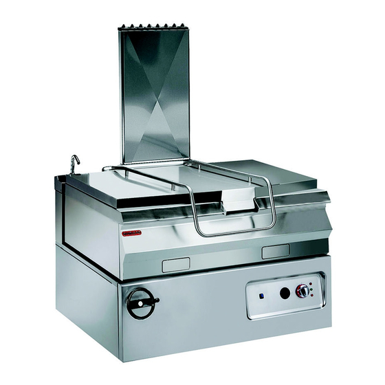
191BR3G (vasca in compound) 291BR3G (vasca in compound) IDM-39616000100.tif Organi principali A)Coperchio vasca B)Vasca di cottura: è realizzata in ferro (191BR1G- 291BR1G) o in acciaio inox (191BR2G-291BR2G o in compound 191BR3G-291BR3G). C)Scarico fumi (tipo A): per evacuare i fumi generati dal bruciatore D)Manovella ribaltamento vasca: per consentire lo svuotamento della vasca. -
Page 7: Dati Tecnici
DATI TECNICI Vedi tabelle e “Scheda allacciamenti” in fondo al manuale. DISPOSITIVI DI SICUREZZA Anche se l'apparecchiatura è completa di tutti i di- spositivi di sicurezza, in fase di installazione e allac- ciamento essi dovranno, se necessario, essere integrati con altri in modo da rispettare le leggi vi- genti in materia. -
Page 8: Accessori A Richiesta
ACCESSORI A RICHIESTA A richiesta l'apparecchiatura può essere corredata dei seguenti accessori. A)Griglia di scarico B)Sifone di scarico C)Piedi di appoggio D)Kit per installazione “a ponte” (vedi pag. 16) E)Kit telaio di appoggio (vedi pag. 16) L) Kit trave di sostegno (vedi pag. 16) IDM-39616000500.tif SICUREZZA NORME PER LA SICUREZZA... -
Page 9: Norme Per La Sicurezza Sull'impatto Ambientale
Nell'uso quotidiano dell'apparecchiatura è richiesta Non lasciare oggetti o materiale infiammabile all'in- la presenza costante dell'Operatore. terno del vano o in prossimità dell'apparecchiatura. Durante il lavaggio dell'apparecchiatura non dirige- re getti d'acqua in pressione sulle parti interne dell'apparecchiatura. NORME PER LA SICUREZZA SULL'IMPATTO AMBIENTALE Ogni organizzazione ha il compito di applicare delle –... -
Page 10: Uso E Funzionamento
USO E FUNZIONAMENTO RACCOMANDAZIONI PER L'USO E FUNZIONAMENTO Importante L'incidenza degli infortuni derivanti cipali. Attuare solo gli usi previsti dal co- dall'uso di apparecchiature dipende da struttore manomettere nessun molti fattori che non sempre si riescono a dispositivo per ottenere prestazioni diverse prevenire e controllare. - Page 11 ACCENSIONE E SPEGNIMENTO BRUCIATORE Accensione Importante Prima di effettuare questa operazione con- trollare che la vasca non sia sollevata e che sia completamente in battuta sulla parte fis- 1 - Aprire il rubinetto alimentazione gas. 2 - Ruotare la manopola (A) in senso orario (pos.
-
Page 12: Inattività Prolungata Dell'apparecchiatura
RIEMPIMENTO E SVUOTAMENTO VASCA Riempimento Importante Prima di effettuare questa operazione con- trollare che la vasca non sia sollevata e che sia completamente in battuta sulla parte fis- 1 - Sollevare il coperchio (A). 2 - Premere l'interruttore (B) per riempire la vasca d'acqua attraverso l'erogatore (C). -
Page 13: Consigli Per L'uso
CONSIGLI PER L'USO Importante Utilizzare l'apparecchiatura per effettuare cotture in umido (brasati, carni al sugo, in- tingoli, ecc.); ogni altro uso è considerato improprio. Al fine di garantire un corretto uso dell'apparecchia- tura, è bene applicare i seguenti consigli. – Utilizzare esclusivamente gli accessori indicati dal costruttore. -
Page 14: Pulizia Apparecchiatura
PULIZIA APPARECCHIATURA Se si considera che l'apparecchiatura è utilizzata Cautela - Avvertenza per la preparazione di prodotti alimentari per l'uo- Non usare prodotti che contengono sostanze mo, è necessario prestare particolare cura a tutto dannose e pericolose per la salute delle per- ciò... -
Page 15: Ricerca Guasti
GUASTI RICERCA GUASTI L'apparecchiatura, prima della messa in servizio, è Alcuni di questi problemi possono essere risolti stata preventivamente collaudata. dall'utilizzatore, per tutti gli altri è richiesta una pre- Le informazioni di seguito riportate hanno lo scopo cisa competenza tecnica o particolari capacità e di aiutare l'identificazione e correzione di eventuali quindi devono essere eseguiti esclusivamente da anomalie e disfunzioni che potrebbero presentarsi... -
Page 16: Movimentazione E Installazione
MOVIMENTAZIONE E INSTALLAZIONE RACCOMANDAZIONI PER LA MOVIMENTAZIONE E INSTALLAZIONE Importante Eseguire la movimentazione e l'installazio- ste operazioni dovrà, se necessario, orga- ne nel rispetto delle informazioni fornite dal nizzare “piano sicurezza” costruttore e riportate direttamente sull'im- salvaguardare l'incolumità delle persone ballo, sull'apparecchiatura e nelle istruzioni direttamente coinvolte. -
Page 17: Installazione Apparecchiatura
INSTALLAZIONE APPARECCHIATURA Tutte le fasi di installazione devono essere conside- rate sin dalla realizzazione del progetto generale. Prima di iniziare tali fasi, oltre alla definizione della zona di installazione, chi è autorizzato ad eseguire queste operazioni dovrà, se necessario, attuare un “piano di sicurezza”... - Page 18 LIVELLAMENTO Agire sui piedi di appoggio (A) per livellare l'appa- recchiatura. IDM-39614401600.tif MONTAGGIO APPARECCHIATURE IN BATTERIA Per montare le apparec- chiature in batteria (fianco a fianco) procedere nel modo indicato. 1 - Applicare del si- gillante per uso alimentare sui lati da accostare.
-
Page 19: Allacciamento Acqua
ALLACCIAMENTO ACQUA Per effettuare l'allacciamento, collegare il tubo di rete con il tubo di attacco dell'apparecchiatura, in- terponendo un rubinetto di intercettazione (A) per interrompere, quando necessario, l'alimentazione dell'acqua. A valle di esso installare dei filtri facil- mente raggiungibili. Cautela - Avvertenza L'apparecchiatura deve essere alimentata con acqua potabile con le caratteristiche indi- cate in tabella. -
Page 20: Allacciamento Elettrico
ALLACCIAMENTO SCARICO FUMI Importante Effettuare l'allacciamento nel rispetto delle leggi vigenti in materia utilizzando il mate- riale appropriato e prescritto. Allacciamento a camino con tiraggio naturale Per questa operazione pro- cedere nel modo indicato. 1 - Collegare la presa di sca- rico dell'apparecchiatura al camino (A), con un tubo che rispetti le dimensioni... - Page 21 2 - Smontare la manovella (C). 3 - Svitare le viti (D) e smontare il cruscotto (E). 4 - Svitare la vite (F) per smontare il coperchio (G). 5 - Collegare l'interruttore sezionatore (A) alla morsettiera (H) dell'apparecchiatura come indi- cato in figura e nello schema elettrico in fondo al manuale.
-
Page 22: Collaudo Apparecchiatura
COLLAUDO APPARECCHIATURA 5 - Verificare la regolare accensione e combustio- Importante ne del bruciatore. 6 - Verificare e, se necessario, regolare la pressio- Prima della messa in servizio, occorre ese- guire il collaudo dell'impianto, per valutare ne e la portata del gas al minimo e al massimo le condizioni operative di ogni singolo com- (vedi pag. - Page 23 REGOLAZIONE MINIMO VALVOLA GAS Importante Questa regolazione si effettua solo se il tipo necessario verificare che la pressione del di gas da allacciare è diverso da quello di gas di alimentazione sia conforme al valore collaudo, dopo avere eseguito la trasforma- della pressione nominale relativa allo stesso zione dell'alimentazione (vedi pag.
- Page 24 REGOLAZIONE ARIA PRIMARIA BRUCIATORE (291BR1G - 291BR2G - 291BR3G) questa operazione procedere nel modo indi- cato. 1 - Chiudere il rubinetto alimentazione gas. 2 - Smontare la manovella (B). 3 - Svitare le viti (C) e smontare il cruscotto (D). 4 - Allentare la vite di bloc- caggio (E).
- Page 25 3 - Svitare la vite (E) per smontare il coperchio (F). 4 - Allentare la vite (G). 5 - Portare la staffa (H) in battuta sul microinterrut- tore (L). 6 - Serrare la vite (G). 7 - Montare il coperchio (F) e fissarlo con la vite (E).
-
Page 26: Sostituzione Parti
SOSTITUZIONE PARTI RACCOMANDAZIONI PER LA SOSTITUZIONE PARTI Prima di effettuare qualsiasi intervento di sostituzio- nenti usurati, utilizzare esclusivamente ricambi ori- ne, attivare tutti i dispositivi di sicurezza previsti e ginali. Si declina ogni responsabilità per danni a valutare la necessità di informare adeguatamente il persone o componenti derivanti dall'impiego di ri- personale che opera e quello nelle vicinanze. - Page 27 SOSTITUZIONE UGELLO SPIA PILOTA questa operazione procedere nel modo indi- cato. 1 - Chiudere il rubinetto alimentazione gas. 2 - Smontare la manovella (B). 3 - Svitare le viti (C) e smontare il cruscotto (D). 4 - Svitare il raccordo (E). 5 - Estrarre l'ugello (F) e sostituirlo con quello IDM-39616002700.tif...
-
Page 28: Dismissione Apparecchiatura
4 - Allentare il dado (E). 5 - Allentare le viti (F) e smontare le boccole (G). 6 - Svitare e sostituire la barra filettata (H). 7 - Regolare la posizione della boccola (L) alla di- stanza riportata in figura. 8 - Rimontare le boccole (G) e serrare le viti (F). - Page 30 The well must be thoroughly washed and dried after use, and a thin even coating of edible oil or fat must be applied to the bottom. 191BR1G (iron well) 291BR1G (iron well) IDM-39616000100.tif Caution - warning...
- Page 31 CONTENTS ref. chapters page 1 GENERAL INFORMATION ..........2 2 TECHNICAL INFORMATION ..........4 3 SAFETY ................6 PART 4 USE AND OPERATION ............. 8 5 SERVICING ..............11 6 FAULT ................13 7 HANDLING AND INSTALLATION ........14 8 ADJUSTMENTS ............... 20 PART 9 REPLACING PARTS ............
-
Page 32: General Information
GENERAL INFORMATION INFORMATION FOR THE READER To find the specific topics of interest to you quickly, 2nd part: contains all the information neces- refer to the index at the start of the manual. sary for special categories of reader, i.e. all This manual is subdivided into two parts. -
Page 33: Procedure For Requesting Service
IDENTIFICATION OF CONSTRUCTOR AND APPLIANCE The nameplate shown here is fitted directly to the ) Gas consumption ) Testing gas indicator frame appliance. It contains references and all essential ) Voltage (V) information for operating safety. ) Frequency (Hz) Extra nameplate ) Electricity power consumption (W) ) Country of use ) Test voltage indicator... -
Page 34: Technical Information
191BR3G (steel compound) 291BR3G (steel compound) IDM-39616000100.tif Main Parts A)Well lid B)Cooking well: in iron (191BR1G-291BR1G) or stainless steel (191BR2G-291BR2G) or compound (191BR3G - 291BR3G). C)Fume exhaust vent (Type A): for removal of the fumes generated by the burner D)Well tilting handle: for emptying out the well. -
Page 35: Technical Data
TECHNICAL DATA See tables and "Connection chart" at the back of the manual. SAFETY DEVICES Although the appliance is complete with all safety devices, during installation and connection addi- tional devices must be added if necessary to com- ply with the relevant legal requirements. The illustration shows the position of the devices. -
Page 36: Optional Accessories
OPTIONAL ACCESSORIES The appliance can be equipped with the following accessories on request. A)Drain grid B)Drain siphon C)Feet D)"Bridge" installation kit (see page 16) E)Supporting frame kit (see page 16) L) Supporting beam kit (see page 16) IDM-39616000500.tif SAFETY SAFETY REGULATIONS During design and construction, the construc- All servicing operations requiring specific technical tor has paid special attention to factors which... - Page 37 During routine use of the appliance, the Operator's Do not leave flammable objects or materials inside constant presence is required. or close to the appliance. When washing the appliance do not point pressu- rised water jets at internal parts. ENVIRONMENTAL IMPACT SAFETY REGULATIONS Every organisation is obliged to apply procedures to –...
-
Page 38: Use And Operation
USE AND OPERATION RECOMMENDATIONS FOR USE Important The rate of accidents deriving from the use and the main functions. Use only as intend- of appliances depends on many factors ed by the constructor and never tamper which cannot always be foreseen and con- with any device to obtain performance lev- trolled. - Page 39 SWITCHING THE BURNER ON AND OFF Lighting Important Before proceeding with this operation check that the well is not raised and resting firmly on fixed part of appliance. 1 - Turn on the gas supply tap. 2 - Turn the knob (A) clockwise (pos. 1) to turn on the electricity supply.
-
Page 40: Lengthy Downtimes Of Appliance
FILLING AND EMPTYING THE WELL Filling Important Before proceeding with this operation check that the well is not raised and resting firmly on fixed part of appliance. 1 - Raise the lid (A). 2 - Press the switch (B) to fill the well with water by means of the spout (C). -
Page 41: Servicing
USEFUL ADVICE FOR USE Important Use the appliance only for slow cooking (braising, stewing, sauces, etc.); all other uses are improper. To ensure correct use of the appliance, the follow- ing rules should be adopted. – Use only the accessories recommended by the constructor. -
Page 42: Cleaning Instructions
CLEANING INSTRUCTIONS Since the appliance is used for preparing foods for Caution - warning human consumption, special care must be paid to Never use products containing substances everything relating to hygiene, and the appliance harmful or hazardous for health (solvents, pe- and the entire surrounding environment must con- troleum spirits, etc.). -
Page 43: Fault
FAULT TROUBLESHOOTING The appliance has been tested before being put The user can solve some of these problems him- into service. self, but for others specific technical knowledge or The information provided below is intended to as- skill is required, and so they must only be carried sist in the identification and correction of any anom- out by qualified staff with recognised experience ac- alies and malfunctions which might occur during... -
Page 44: Handling And Installation
HANDLING AND INSTALLATION RECOMMENDATIONS FOR HANDLING AND INSTALLATION Important When handling and installing the appliance use. If necessary, the person authorised to comply with the information provided by carry out these operations must organise a the constructor directly on the packaging, "safety plan"... -
Page 45: Installation Of The Appliance
INSTALLATION OF THE APPLIANCE All installation stages must be considered right from production of the general layout. Before starting these stages, as well as deciding the place of installation, if necessary, the person authorised to carry out these operations must organise a "safety plan" to protect the people directly involved, and he must also ensure strict compliance with all legal requirements, especial- ly those relating to mobile work-sites. - Page 46 LEVELLING Adjust the floor-mounted feet (A) to level the appli- ance. IDM-39614401600.tif ASSEMBLY APPLIANCES IN BANKS To assemble appliances in banks (side by side) pro- ceed as described below. 1 - Apply food-approved sealant to the edg- es to be placed side by side.
-
Page 47: Water Connection
WATER CONNECTION To make the connection, connect the mains line to the appliance's connection pipe, fitting a shut-off tap (A), to allow the water supply to be cut off when necessary. Easily accessible filters must be fitted downstream of the tap. Caution - warning The appliance must be supplied with drinking water having the characteristics shown in the... -
Page 48: Electrical Connection
CONNECTION OF FUME EXHAUST VENT Important Make the connection in compliance with the relevant legal requirements, using ap- propriate and recommended materials. Connecting to a flue with natural draught To carry out this operation, proceed as follows. 1 - Connect the appliance's exhaust outlet to the flue (A) using a line comply- ing with the dimensions... -
Page 49: Conversion Of Gas Supply
2 - Remove the knob (C). 3 - Undo the screws (D) and remove the control panel (E). 4 - Undo the screws (F) to remove the lid (G). 5 - Connect the circuit-breaker (A) to the terminal board (H) of the appliance as shown in the dia- gram and in the electrical system diagram at the back of the manual. -
Page 50: Testing Of The Appliance
TESTING OF THE APPLIANCE 5 - Check that the burner is switching on correctly Important and its combustion. 6 - Check the gas pressure and flow-rate at mini- Before it is put into service, the system must be tested to check the operating con- mum and maximum settings and adjust if nec- ditions of every single component and essary (see page 21). - Page 51 ADJUSTING GAS VALVE MINIMUM SETTING Important This adjustment is only required if the type fore making this adjustment, check that the of gas to be connected is different from that gas supply pressure is the same as the rat- used for testing after the conversion proce- ed pressure for the type of gas in use (see dure has been carried out (see page 19).
- Page 52 ADJUSTING BURNER PRIMARY AIR (291BR1G - 291BR2G - 291BR3G) To carry out this operation, proceed as follows. 1 - Turn off the gas supply tap. 2 - Remove the knob (B). 3 - Undo the screws (C) and remove the control panel (D).
- Page 53 3 - Undo the screws (E) to remove the lid (F). 4 - Undo the screw (G). 5 - Position the bracket (H) so that it is touching the microswitch (L). 6 - Tighten the screw (G). 7 - Fit the lid (F) and secure it with the screw (E). 8 - Replace the control panel (D) and the knob (B) on completion of the operation.
-
Page 54: Replacing Parts
REPLACING PARTS RECOMMENDATIONS FOR REPLACING PARTS Before carrying out any replacement procedure, ac- clines all responsibly for injury or damage to com- tivate all the safety devices provided and decide ponents due to the use of non original parts, or whether staff at work and those in the vicinity extraordinary work on the appliance which may should be informed. - Page 55 REPLACEMENT OF THE PILOT LIGHT INJECTOR To carry out this operation, proceed as follows. 1 - Turn off the gas supply tap. 2 - Remove the knob (B). 3 - Undo the screws (C) and remove the control panel (D). 4 - Unscrew the union (E).
-
Page 56: Decommissioning The Appliance
4 - Undo the nut (E). 5 - Undo the screws (F) and remove the bushes (G). 6 - Unscrew and replace the threaded rod (H). 7 - Set the bush (L) at the distance as shown in the figure. 8 - Reassemble the bushes (G) and tighten the screws (F). - Page 58 Die Brat- pfanne muss nach Gebrauch sorgfältig gewa- schen und getrocknet werden. Außerdem muss der Pfannenboden mit einem dünnen Film Speiseöl oder Speisefett bedeckt werden. 191BR1G (Bratpfanne aus Eisen) 291BR1G (Bratpfanne aus Eisen) IDM-39616000100.tif stimmungen vornehmen. Vorsicht - Achtung Vor Ausführung irgendeines Eingriffs die...
- Page 59 INHALTSVERZEICHNIS Ref. Kapitel Seite 1 ALLGEMEINES ..............2 2 TECHNISCHE INFORMATIONEN ........4 3 SICHERHEIT ..............6 1. TEIL 4 GEBRAUCH UND BETRIEB ..........8 5 WARTUNG ............... 11 6 DEFEKTE ................. 13 7 HANDHABUNG UND INSTALLATION ......14 8 EINSTELLUNGEN ............20 2.
-
Page 60: Allgemeines
ALLGEMEINES INFORMATIONEN FÜR DEN LESER Konsultieren Sie das Sachregister, das am Anfang 2. Teil: Diese Informationen wenden sich an des Handbuchs zu finden ist, um leichter unter be- eine bestimmte Zielgruppe. Sie sind für erfahre- stimmten Themen von besonderem Interesse ne Bediener bestimmt, die für Handhabung, nachschlagen zu können. -
Page 61: Typenschild Für Hersteller Und Gerät
TYPENSCHILD FÜR HERSTELLER UND GERÄT Das abgebildete Typenschild wird direkt auf dem ) Gasverbrauch ) Testgasanzeige Gerät aufgebracht. Es enthält sämtliche Angaben ) Spannung (V) und Hinweise, die für den sicheren Betrieb unerläs- ) Frequenz (Hz) slich sind. ) Leistungsaufnahme (W) Ergänzungsschild ) Abnahmespannungsanzeige ) Benutzerland... -
Page 62: Technische Informationen
191BR3G (Bratpfanne aus Verbundstoff) 291BR3G (Bratpfanne aus Verbundstoff) IDM-39616000100.tif Hauptorgane A)Verschlussdeckel für Becken B)Bratpfanne: Sie besteht aus Eisen (191BR1G- 291BR1G) oder aus Edelstahl (191BR2G-291BR2G) oder aus Verbundstoff 191BR3G-291BR3G. C)Rauchabzug (Typ A): zum Abführen der vom Bren- ner erzeugten Rauchgase D)Kurbel für Kippen der Bratpfanne: zum Entleeren der Bratpfanne. -
Page 63: Technische Daten
TECHNISCHE DATEN Siehe Tabellen und „Anschlussschema" am Ende des Handbuchs. SICHERHEITSVORRICHTUNGEN Das Gerät wird zwar mit sämtlichen planmäßigen Sicherheitsvorrichtungen geliefert, es kann jedoch notwendig sein, während Installation und An- schluss ggf. weitere ergänzende Maßnahmen zu ergreifen, um den Anforderungen der einschlägi- gen geltenden Gesetze zu entsprechen. -
Page 64: Optionales Zubehör
OPTIONALES ZUBEHÖR Auf Wunsch kann das Gerät mit folgenden Zube- hörteilen ausgestattet werden. A)Abflussgitter B)Siphon C)Stützfüße D)Einbausatz für Brückenmontage (siehe Seite 16). E)Einbausatz für Untergestell (siehe Seite 16). L) Einbausatz für Träger (siehe Seite 16). IDM-39616000500.tif SICHERHEIT SICHERHEITSVORSCHRIFTEN Der Hersteller hat bei Entwicklung und Ferti- wiegende Gefahren für Sicherheit und Gesundheit gung dieses Produkts besondere Sorgfalt auf von Personen und finanzielle Verluste hervorrufen. - Page 65 Beim täglichen Gebrauch des Geräts ist die ständi- Keine entzündlichen Gegenstände oder Materialien ge Anwesenheit des Bedienungspersonals erfor- im Schrank oder in der Nähe des Geräts aufbewah- derlich. ren. Beim Waschen des Geräts den Wasserstrahl nicht direkt auf die inneren Teile des Geräts richten. SICHERHEITSVORSCHRIFTEN IN HINBLICK AUF DIE UMWELTBELASTUNG Alle Betriebe müssen den Einfluss, den ihre Tätig- –...
-
Page 66: Gebrauch Und Betrieb
GEBRAUCH UND BETRIEB EMPFEHLUNGEN FÜR DEN GEBRAUCH Wichtig Das Auftreten von Unfällen bei der Verwen- schränken Sie sich auf die vom Hersteller dung von Geräten hängt von vielen Fakto- vorgesehenen Verwendungszwecke, ohne ren ab, die nicht immer zu vermeiden und Änderungen an den Vorrichtungen vorzu- zu steuern sind. - Page 67 EIN- UND AUSSCHALTEN DES BRENNERS Zündung Wichtig Vor Ausführung dieses Vorgangs sicher- stellen, dass die Bratpfanne nicht angeho- ben ist bzw. dass sie richtig auf dem festen Unterteil aufliegt. 1 - Öffnen Sie den Gashahn. 2 - Den Schalter (A) im Uhrzeigersinn (Pos. 1) dre- hen, um die Stromzufuhr zu aktivieren.
-
Page 68: Längerer Stillstand Des Geräts
FÜLLEN UND ENTLEEREN DES BECKENS Füllen Wichtig Vor Ausführung dieses Vorgangs sicher- stellen, dass die Bratpfanne nicht angeho- ben ist bzw. dass sie richtig auf dem festen Unterteil aufliegt. 1 - Den Deckel (A) anheben. 2 - Den Schalter (B) drücken, um die Bratpfanne über das Wasserzulaufrohr (C) mit Wasser zu füllen. -
Page 69: Tipps Für Den Gebrauch
TIPPS FÜR DEN GEBRAUCH Wichtig Das Gerät dient zum Schmoren (Schmor- braten, Fleisch in Soße, Tunken usw.). Je- der andere Gebrauch ist als zweckwidrig anzusehen. Um eine korrekte Anwendung des Gerätes zu ge- währleisten, sollten folgende Ratschläge befolgt werden: – Verwenden Sie ausschließlich das vom Herstel- IDM-39616001100.tif ler angegebene Zubehör. -
Page 70: Reinigung Des Geräts
REINIGUNG DES GERÄTS Da das Gerät zur Zubereitung von Speisen für den Menschen eingesetzt wird, ist besondere Sorgfalt Vorsicht - Achtung auf die Hygiene geboten. Das Gerät und dessen Verwenden Sie keine Produkte, die Stoffe ent- näheres Umfeld müssen konstant sauber gehalten halten, welche für die menschliche Gesund- werden. -
Page 71: Defekte
DEFEKTE FEHLERSUCHE Vor der Inbetriebnahme wurde das Gerät einem selbst behoben werden; alle anderen erfordern prä- vorläufigen Testlauf unterzogen. zise Fachkenntnisse oder besondere Fähigkeiten Die im Folgenden aufgeführten Informationen sol- und dürfen daher ausschließlich von qualifiziertem len Ihnen dabei helfen, eventuelle Anomalien oder Personal mit nachweislicher Erfahrung in diesem Funktionsstörungen, die während des Betriebs auf- speziellen Gebiet des Eingriffs durchgeführt wer-... -
Page 72: Handhabung Und Installation
HANDHABUNG UND INSTALLATION EMPFEHLUNGEN FÜR DIE INSTALLATION UND HANDHABUNG Wichtig Beachten Sie die Hinweise des Herstellers, nen autorisierte Person wird bei Bedarf die direkt auf der Verpackung, auf dem Ge- einen „Sicherheitsplan" aufstellen müssen, rät selbst oder in der Gebrauchsanweisung um die Unversehrtheit der direkt an dem zu finden sind, wenn Sie das Gerät handha- Vorgang beteiligten Personen zu gewähr-... -
Page 73: Installation Des Geräts
INSTALLATION DES GERÄTS Es müssen sämtliche Phasen der Installation, schon von der Umsetzung des allgemeinen Pro- jekts an, berücksichtigt werden. Die für diese Ope- rationen autorisierte Person wird vor Einleitung dieser Phasen den Installationsstandort bestimmen und bei Bedarf einen „Sicherheitsplan" aufstellen, um die Unversehrtheit der direkt am Vorgang betei- ligten Personen zu gewährleisten und die gesetzli- chen Bestimmungen zu befolgen. - Page 74 NIVELLIEREN Regulieren Sie die Füße (A), um das Gerät wasser- waagengerecht aufzustellen. IDM-39614401600.tif MONTAGE BEI REIHENAUFSTELLUNG Verfahren Sie folgender- maßen, um Geräte (neben- einander) in einer Reihe aufzustellen. 1 - Beschichten Sie die Seitenwände, die nebeneinan- aufgestellt werden sollen, mit einer Dichtungs- masse für Lebensmit- telzwecke.
- Page 75 WASSERANSCHLUSS Schließen Sie den Zufuhrschlauch der Wasserlei- tung an das Anschlussrohr des Gerätes an. Bringen Sie hierbei einen Absperrhahn (A) an, um die Was- serzufuhr bei Bedarf absperren zu können. Hinter diesen Absperrhahn müssen leicht zugängliche Fil- ter eingebaut werden. Vorsicht - Achtung Das Gerät muss mit Trinkwasser gespeist werden, dass die in der Tabelle angegebenen...
- Page 76 ANSCHLUSS DES RAUCHABZUGS Wichtig Den Anschluss in Einklang mit den ein- ten und vorgeschriebenen Materials aus- schlägigen gesetzlichen Bestimmungen führen. und unter Verwendung des hierfür geeigne- Anschluss an ein Abzugs- rohr mit natürlicher Ansau- gung Für diesen Vorgang in der angegebenen Weise verfah- ren.
- Page 77 2 - Die Kurbel (C) ausbauen. 3 - Drehen Sie die Schrauben (D) heraus und montieren Sie die Blende (E) ab. 4 - Die Schraube (F) ausschrauben, um den Dek- kel (G) auszubauen. 5 - Den Trennschalter (A) nach den Angaben in der Abbildung und im Schaltplan am Ende des Handbuchs an die Klemmenleiste (H) des Ge- räts anschließen.
-
Page 78: Einstellungen
TESTLAUF ZUR ABNAHME DES GERÄTS 5 - Sicherstellen, dass Zündung und Verbrennung Wichtig beim Brenner ordnungsgemäß funktionieren. 6 - Überprüfen Sie Gasdruck und –durchsatz bei Vor der Inbetriebnahme muss ein Testlauf der Anlage durchgeführt werden, um den minimaler und maximaler Zufuhr und regulieren Betriebszustand jeder einzelnen Kompo- Sie, falls notwendig, die Einstellungen (siehe nente zu überprüfen und eventuelle An-... - Page 79 EINSTELLUNG DER KLEINSTELLUNG DES GASVENTILS Wichtig Diese Einstellung muss nur ausgeführt man sicherstellen, dass der Druck im Gas- werden, wenn die anzuschließende Gasart netz dem für die jeweilige Gasart vorge- von der Prüfgasart verschieden ist, d.h. schriebenen Nenndruck entspricht (siehe also im Anschluss an eine Gasumstellung die Tabelle am Ende des Handbuchs).
- Page 80 EINSTELLUNG DER PRIMÄRLUFT DES BRENNERS (291BR1G - 291BR2G-291BR3G) Für diesen Vorgang in der angegebenen Weise ver- fahren. 1 - Schließen Gaszufuhrhahn 2 - Die Kurbel (B) ausbau- 3 - Drehen Schrauben (C) heraus und montieren Sie die Blende (D) ab. 4 - Die Klemmschraube 42±1...
-
Page 81: Einstellung Der Auswuchtung Des Deckels
3 - Die Schraube (E) ausschrauben, um den Dek- kel (F) auszubauen. 4 - Die Schraube (G) lockern. 5 - Die Platte (H) in Kontakt mit dem Mikroschalter (L) bringen. 6 - Ziehen Sie die Schraube (G) fest. 7 - Den Deckel (F) montieren und mit der Schrau- be (E) befestigen. -
Page 82: Austausch Von Bauteile
AUSTAUSCH VON BAUTEILE HINWEISE ZUM AUSTAUSCH VON TEILEN Vor jedem Eingriff zur Ersetzung eines Teils müssen darf Komponenten, die Verschleißerscheinungen zei- sämtliche vorgesehenen Sicherheitsvorrichtungen ak- gen, verwenden dabei ausschließlich tiviert werden. Überlegen Sie, ob es notwendig ist, das Originalersatzteile. Es wird jede Haftung für Personen- arbeitende Personal und die in der Nähe befindlichen oder Komponentenschäden abgelehnt, die entstehen, Personen auf angemessene Weise zu informieren. - Page 83 AUSWECHSELN DES ZÜNDFLAMMENBRENNERS Für diesen Vorgang in der angegebenen Weise ver- fahren. 1 - Schließen Gaszufuhrhahn 2 - Die Kurbel (B) ausbau- 3 - Drehen Schrauben (C) heraus und montieren Sie die Blende (D) ab. 4 - Drehen Sie das Ver- bindungsstück (E) her- IDM-39616002700.tif aus.
-
Page 84: Entsorgung Des Geräts
4 - Die Mutter (E) lockern. 5 - Die Schrauben (F) lockern und die Buchsen (G) ausbauen. 6 - Die Gewindestange (H) losschrauben und aus- wechseln. 7 - Die Buchse (L) auf den in der Abbildung ange- gebenen Abstand positionieren. 8 - Die Buchsen (G) wieder montieren und die Schrauben (F) anziehen. - Page 86 À la fin de son utilisation, la cuve doit être très bien la- vée et essuyée et sur le fond étaler unifor- mément un voile d’huile ou de graisse alimentaire. 191BR1G (cuve en fer) 291BR1G (cuve en fer) IDM-39616000100.tif Attention Important Avant toute intervention, couper l’alimenta-...
-
Page 87: Index Analytique
INDEX réf. chapitres page 1 INFORMATIONS GENERALES ......... 2 2 INFORMATIONS TECHNIQUES ........4 3 SÉCURITÉ ................. 6 PARTIE 4 UTILISATION ET FONCTIONNEMENT ......8 5 ENTRETIEN ..............11 6 PANNES ................13 7 MANUTENTION ET INSTALLATION ....... 14 8 RÉGLAGES ..............20 PARTIE 9 REMPLACEMENT DE PIÈCES ........ -
Page 88: Informations Generales
INFORMATIONS GENERALES INFORMATIONS POUR LE LECTEUR Pour retrouver facilement les sujets qui vous inté- 2e partie: elle contient toutes les informa- ressent, consulter l’index analytique au début du tions nécessaires aux destinataires homogè- manuel. nes, c'est-à-dire tous les opérateurs experts Ce manuel est divisé... -
Page 89: Identification Du Fabricant Et De L'appareil
IDENTIFICATION DU FABRICANT ET DE L’APPAREIL La plaque d’identification représentée, est appli- ) Puissance déclarée (kW) ) Consommation de gaz quée directement sur l'appareil. Elle reporte les ré- ) Indicateur du gaz d’essai férences et les indications indispensables à la ) Tension (V) sécurité. -
Page 90: Informations Techniques
291BR3G (cuve en matériau composite) IDM-39616000100.tif Organes principaux A)Couvercle de la cuve B)Cuve de cuisson: elle est en fer 191BR1G- 291BR1G ou en acier inox 191BR2G-291BR2G ou en matériau composite191BR3G-291BR3G. C)Évacuation des fumées (Type A): pour évacuer les fumées générées par le brûleur D)Manivelle de basculement de la cuve: pour per- mettre la vidange de la cuve. -
Page 91: Données Techniques
DONNÉES TECHNIQUES Voir tableaux et « Fiche des raccordements » à la fin du manuel. DISPOSITIFS DE SÉCURITÉ Même si l’appareil est complet de tous les disposi- tifs de sécurité, lors de l’installation et du raccorde- ment, ils devront, si nécessaire, être intégrés avec d’autres pour respecter les lois en vigueur. -
Page 92: Accessoires Sur Demande
ACCESSOIRES SUR DEMANDE Sur demande l'appareil peut être équipé des acces- soires suivants. A)Grille de vidange B)Siphon de vidange C)Pieds d’appui D)Kit pour installation « en pont » (voir page 16) E)Kit bâti d’appui (voir page 16) L) Kit traverse de soutien (voir page 16) IDM-39616000500.tif SÉCURITÉ... -
Page 93: Normes Pour La Sécurité Sur L'impact Environnemental
Un opérateur doit être constamment présent pen- Ne pas laisser d’objets ou de matériau inflammable dant l’utilisation quotidienne de l’appareil. à l’intérieur du compartiment ou à proximité de l’ap- pareil. Pendant le lavage de l’appareil ne pas diriger de jets d’eau sous pression sur les pièces intérieures. NORMES POUR LA SÉCURITÉ... -
Page 94: Utilisation Et Fonctionnement
UTILISATION ET FONCTIONNEMENT RECOMMANDATIONS POUR L'UTILISATION Important L'incidence des accidents dérivant de l'uti- les. Utiliser seulement comme prévu par le lisation d'appareils dépend de beaucoup de fabricant et ne modifier aucun dispositif facteurs que l'on ne peut pas toujours pré- pour obtenir des performances différentes venir et contrôler. -
Page 95: Allumage Et Extinction Du Brûleur
ALLUMAGE ET EXTINCTION DU BRÛLEUR Allumage Important Avant d’effectuer cette opération, contrôler que la cuve ne soit pas soulevée et qu’elle soit complètement en butée sur la partie fixe. 1 - Ouvrir le robinet d’alimentation du gaz. 2 - Tourner la manette (A) en sens horaire (pos. 1) pour activer l'alimentation électrique. -
Page 96: Remplissage Et Vidange De La Cuve
REMPLISSAGE ET VIDANGE DE LA CUVE Remplissage Important Avant d’effectuer cette opération, contrôler que la cuve ne soit pas soulevée et qu’elle soit complètement en butée sur la partie fixe. 1 - Lever le couvercle (A). 2 - Appuyer sur l'interrupteur (B) pour remplir la cuve d’eau par l'érogateur (C). -
Page 97: Conseils D'utilisation
CONSEILS D’UTILISATION Important Utiliser l'appareil pour la cuisson de vian- des en sauce (viandes braisées, ragoûts, etc.); toute autre utilisation est considérée impropre. Afin de garantir une utilisation correcte de l’appa- reil, suivre ces conseils. – Utiliser exclusivement les accessoires indiqués par le fabricant. -
Page 98: Nettoyage De L'appareil
NETTOYAGE DE L’APPAREIL Étant donné que l'appareil est utilisé pour la prépa- Attention ration de produits alimentaires pour l'homme, il faut Ne pas utiliser de produits qui contiennent faire attention à tout ce qui concerne l'hygiène; l'ap- des substances dangereuses pour la santé pareil et tout ce qui l'entoure doivent toujours être des personnes (solvants, essences, etc.). -
Page 99: Dépannage
PANNES DÉPANNAGE Avant sa mise en service, l’appareil a été essayé. l'utilisateur, pour tous les autres il faut une compé- Les informations reportées ci-après ont pour but tence technique précise ou des capacités particu- d’aider à l'identification et à la correction d’éven- lières;... -
Page 100: Manutention Et Installation
MANUTENTION ET INSTALLATION RECOMMANDATIONS POUR LA MANUTENTION ET L’INSTALLATION Important Effectuer la manutention et l’installation en effectuer ces opérations devra, si nécessai- respectant les informations fournies par le re, organiser un « plan de sécurité » pour fabricant, reportées directement sur l’em- sauvegarder la sécurité... -
Page 101: Mise En Place De L'appareil
MISE EN PLACE DE L’APPAREIL Toutes les phases de mise en place doivent être prises en considération, dès la réalisation du projet général. Avant de commencer ces phases, outre la définition de la zone de mise en place, celui qui est autorisé... -
Page 102: Mise À Niveau
MISE À NIVEAU Agir sur les pieds d’appui (A) pour mettre de niveau l’appareil. IDM-39614401600.tif MONTAGE DES APPAREILS EN BATTERIE Pour monter les appareils en batterie (les uns à côté des autres), procéder com- me suit. 1 - Appliquer de l’ad- hésif pour usage alimentaire les côtés à... -
Page 103: Raccordement Du Gaz
RACCORDEMENT DE L'EAU Pour effectuer le raccordement, raccorder le tuyau de réseau et le tuyau de raccord de l’appareil, en in- terposant un robinet d’arrêt (A), pour interrompre, si nécessaire, l’alimentation de l’eau. En aval de celui- ci, installer des filtres facilement accessibles. Attention L’appareil doit être alimenté... -
Page 104: Raccordement Évacuation Des Fumées
RACCORDEMENT ÉVACUATION DES FUMÉES Important Effectuer le raccordement conformément aux lois en vigueur à ce sujet en utilisant le matériel approprié et prescrit. Raccordement à une mitre à tirage naturel Pour cette opération, procé- der comme suit. 1 - Raccorder la prise d’éva- cuation de l’appareil à... -
Page 105: Transformation De L'alimentation
2 - Démonter la manivelle (C). 3 - Dévisser les vis (D) et démonter le tableau de commandes (E). 4 - Dévisser la vis (F) pour démonter le couvercle (G). 5 - Connecter l'interrupteur sectionneur (A) au bor- nier (H) de l'appareil comme indiqué sur la figu- re et dans le schéma électrique à... -
Page 106: Essai De L'appareil
ESSAI DE L’APPAREIL 5 - Vérifier l'allumage régulier et la combustion du Important brûleur. 6 - Vérifier et, si nécessaire, régler la pression et le Avant la mise en service, l’essai de l’instal- lation doit être fait pour évaluer les condi- débit du gaz au minimum et au maximum (voir tions opérationnelles... -
Page 107: Réglage Du Minimum Du Robinet Gaz
RÉGLAGE DU MINIMUM DU ROBINET GAZ Important Ce réglage n'est effectué que si le type de du gaz d'alimentation soit conforme à la va- gaz à raccorder est différent de celui d'es- leur de la pression nominale relative au sai et après avoir effectué la transformation même type de gaz (voir tableau à... -
Page 108: Réglage Du Microcontact De Fin De Course De La Cuve
RÉGLAGE AIR PRIMAIRE DU BRÛLEUR (291BR1G - 291BR2G - 291BR3G) Pour cette opération, pro- céder comme suit. 1 - Fermer le robinet d’ali- mentation du gaz. 2 - Démonter la manivelle (B). 3 - Dévisser les vis (C) et démonter le tableau de commandes (D). -
Page 109: Réglage De L'équilibre Du Couvercle
3 - Dévisser la vis (E) pour démonter le couvercle (F). 4 - Desserrer les vis (G). 5 - Porter l’étrier (H) en butée sur le microcontact (L). 6 - Serrer la vis (G). 7 - Monter le couvercle (F) et le fixer avec la vis (E). 8 - Remonter le tableau de commandes (D) et la manivelle (B) lorsque l’opération est terminée. -
Page 110: Remplacement De Pièces
REMPLACEMENT DE PIÈCES RECOMMANDATIONS POUR LE REMPLACEMENT DES PIÈCES Avant d’effectuer tout remplacement, activer tous usés, utiliser exclusivement des pièces de rechan- les dispositifs de sécurité prévus et évaluer s’il faut ge d’origine. Le fabricant décline toute responsabi- informer les opérateurs travaillant sur l'appareil et lité... -
Page 111: Remplacement De La Buse De La Veilleuse Pilote
REMPLACEMENT DE LA BUSE DE LA VEILLEUSE PILOTE Pour cette opération, pro- céder comme suit. 1 - Fermer le robinet d’ali- mentation du gaz. 2 - Démonter la manivelle (B). 3 - Dévisser les vis (C) et démonter le tableau de commandes (D). -
Page 112: Elimination De L'appareil
4 - Desserrer l’écrou (E). 5 - Desserrer les vis (F) et démonter les douilles (G). 6 - Dévisser et remplacer la barre filetée (H). 7 - Régler la position de la bague (L) à la distance reportée sur la figure. 8 - Remonter les douilles (G) et serrer les vis (F). - Page 114 Es necesario lavar y secar cuidadosamente la cuba una vez que se ha 191BR1G (cuba de hierro) 291BR1G (cuba de hierro) IDM-39616000100.tif formidad con lo dispuesto por las leyes vi- gentes en esta materia.
- Page 115 ÍNDICE ref. capítulos pág 1 INFORMACIONES DE CARÁCTER GENERAL ....2 2 INFORMACIONES DE CARÁCTER TÉCNICO ....4 3 SEGURIDAD ..............6 PARTE 4 USO Y FUNCIONAMIENTO ..........8 5 MANTENIMIENTO ............11 6 AVERÍAS ................13 7 DESPLAZAMIENTO E INSTALACIÓN ......14 8 REGULACIONES .............
-
Page 116: Informaciones De Carácter General
INFORMACIONES DE CARÁCTER GENERAL INFORMACIONES PREVIAS Para ubicar fácilmente los temas específicos de in- 2a parte: contiene todas las informaciones terés, consúltese el índice analítico que se encuen- necesarias para destinatarios homogéneos, tra al inicio del manual. esto es, todos los operadores expertos y au- Este manual comprende dos partes. -
Page 117: Identificación Fabricante Y Equipo
IDENTIFICACIÓN FABRICANTE Y EQUIPO La placa de identificación fijada directamente en el ) Consumo de gas ) Indicador gas prueba de funcionamiento equipo reproduce todas las referencias e indicacio- ) Tensión (V) nes indispensables para la seguridad de servicio. ) Frecuencia (Hz) Placa complementaria ) Potencia eléctrica absorbida (W) ) País de uso... -
Page 118: Informaciones De Carácter Técnico
291BR3G (cuba de material compuesto) IDM-39616000100.tif Órganos principales A)Tapa cuba B)Cuba de cocción: es realizada en hierro (191BR1G-291BR1G) o en acero inox (191BR2G- 291BR2G) o en material compuesto (191BR3G- 291BR3G). C)Salida de humos (Tipo A): para evacuar los humos generados por el quemador D)Manivela de vuelco cuba: para obtener el vaciado de la cuba. -
Page 119: Datos Técnicos
DATOS TÉCNICOS Véase tablas y "Ficha de enlaces" al final del ma- nual. DISPOSITIVOS DE SEGURIDAD Aunque el equipo cuente con todos los dispositivos de seguridad, en los casos en que así lo determi- nen las leyes vigentes en materia, se deberá com- plementar con otros dispositivos en las fases de instalación y enlace. -
Page 120: Accesorios Bajo Pedido
ACCESORIOS BAJO PEDIDO Bajo pedido, el equipo puede ser suministrado con los accesorios que a continuación se indican. A)Rejilla de descarga B)Sifón de desagüe C)Pies de apoyo D)Kit para la instalación "de puente" (véase pág. 16). E)Kit bastidor de apoyo (véase pág. 16). L) Kit barra de soporte (véase pág. - Page 121 Durante el uso cotidiano del aparato se requiere la No dejar objetos o material inflamable en el interior presencia constante del operador. del compartimiento ni en proximidad del aparato. Durante el lavado del aparato no dirigir chorros de agua a presión hacia sus partes internas. NORMAS DE SEGURIDAD RELATIVAS AL IMPACTO AMBIENTAL Toda organización tiene el deber de aplicar proce- –...
-
Page 122: Uso Y Funcionamiento
USO Y FUNCIONAMIENTO RECOMENDACIONES DE USO Importante El porcentaje de accidentes derivados del Se deben ejecutar sólo operaciones pro- uso de equipos depende de muchos facto- pias de los usos previstos por el fabricante. res que no siempre se logran prevenir y No alterar los equipos con el fin de obtener controlar. - Page 123 ENCENDIDO Y APAGADO DEL QUEMADOR Encendido Importante Antes de efectuar esta operación controlar que la cuba no esté elevada y que se en- cuentre completamente en contacto en la parte fija. 1 - Abrir el grifo de alimentación del gas. 2 - Girar el mando (A) en sentido horario (pos.
-
Page 124: Período Prolongado De Inactividad Del Equipo
LLENADO Y VACIADO DE LA CUBA Llenado Importante Antes de efectuar esta operación controlar que la cuba no esté elevada y que se en- cuentre completamente en contacto en la parte fija. 1 - Levantar la tapa (A). 2 - Presionar el interruptor (B) para llenar la cuba con agua mediante el grifo (C). -
Page 125: Consejos Para El Uso
CONSEJOS PARA EL USO Importante Utilizar el aparato para guisar (braseados, estofados, carnes en salsa, etc.); todo otro uso será considerado como impropio. A fin de garantizar un uso correcto del equipo, apli- car las siguientes recomendaciones. – Utilizar exclusivamente los accesorios indicados por el fabricante. -
Page 126: Limpieza Aparato
LIMPIEZA APARATO Atendida la circunstancia de que el equipo es utili- Precaución - advertencia zado para la preparación de productos alimenticios No usar productos que contengan sustancias para el consumo humano, es necesario prestar es- nocivas y/o peligrosas para la salud de las pecial atención a todo lo referente a la higiene, personas (disolventes, bencinas, etc.). -
Page 127: Averías
AVERÍAS BÚSQUEDA DE AVERÍAS Antes de la puesta en servicio, el equipo ha sido so- Algunos de estos problemas pueden ser resueltos por metido a prueba de funcionamiento. el usuario, pero otros requieren una competencia téc- Las siguientes informaciones tienen por objeto faci- nica precisa o determinadas capacidades, razón por litar la identificación y corrección de eventuales la cual deben ser resueltos exclusivamente por perso-... -
Page 128: Desplazamiento E Instalación
DESPLAZAMIENTO E INSTALACIÓN RECOMENDACIONES PARA EL DESPLAZAMIENTO Y LA INSTALACIÓN Importante Efectuar el desplazamiento e instalación rizada para efectuar estas operaciones de- respetando las indicaciones proporciona- berá, si fuera necesario, organizar un "plan das por el fabricante, reproducidas directa- de seguridad", a fin de salvaguardar la in- mente sobre el embalaje, en el equipo y en columidad de las personas directamente las instrucciones de uso. -
Page 129: Instalación Del Equipo
INSTALACIÓN DEL EQUIPO Durante la realización del proyecto general, deben ser consideradas todas las fases de la instalación. Antes de comenzar dichas fases, además de esta- blecer la zona de instalación, la persona autorizada a efectuar estas operaciones deberá, si fuera nece- sario, aplicar un "plan de seguridad"... - Page 130 NIVELACIÓN Operar con las patas de apoyo (A) para nivelar el equipo. IDM-39614401600.tif MONTAJE DE EQUIPOS EN BATERÍA Para montar los equipos en batería (uno al lado del otro) aplicar las siguientes instrucciones. 1 - Poner material sellador para uso alimenticio sobre los lados a juntar.
- Page 131 ENLACE AGUA Para efectuar el enlace, conectar el tubo de red con el tubo de conexión del equipo, instalando un grifo de interceptación (A) a fin de poder interrumpir, cuando sea necesario, la alimentación del agua. En posición sucesiva al grifo se deben instalar filtros de fácil acceso.
-
Page 132: Conexión A La Salida De Humos
CONEXIÓN A LA SALIDA DE HUMOS Importante Llevar a cabo la conexión respetando las leyes vigentes en materia y utilizar siempre el material adecuado y previsto por el constructor. Conexión a la chimenea con tiro natural Para efectuar esta opera- ción, aplicar las siguientes instrucciones. - Page 133 2 - Desmontar la manivela (C). 3 - Desenroscar los tornillos (D) y desmontar el ta- blero de instrumentos (E). 4 - Desenroscar el tornillo (F) para desmontar la tapa (G). 5 - Conectar el interruptor seccionador (A) a la bornera (H) del aparato de la manera ilustrada en la figura y en el esquema eléctrico al final del manual.
-
Page 134: Regulaciones
PRUEBA DE FUNCIONAMIENTO DEL EQUIPO 5 - Controlar el correcto encendido y combustión Importante del quemador. 6 - Controlar y, si fuera necesario, regular la pre- Antes de la puesta en servicio debe efec- tuarse la prueba de funcionamiento del sis- sión y el caudal del gas al mínimo y al máximo tema, a fin de evaluar las condiciones (véase pág. - Page 135 REGULACIÓN MÍNIMO VÁLVULA GAS Importante Esta regulación deberá efectuarse sólo si el deberá verificar que la presión del gas de ali- tipo de gas a conectar es diferente de aquél de mentación corresponda al valor de presión no- prueba en fábrica y después de haber efectua- minal relativo a ese tipo de gas (véase tabla en do la transformación de la alimentación (véase la parte conclusiva del manual).
- Page 136 REGULACIÓN AIRE PRIMARIO QUEMADOR (291BR1G - 291BR2G - 291BR3G) Para efectuar esta opera- ción, aplicar las siguientes instrucciones. 1 - Cerrar el grifo de ali- mentación del gas. 2 - Desmontar la manivela (B). 3 - Desenroscar los torni- llos (C) y desmontar el tablero de instrumen- tos (D).
- Page 137 3 - Desenroscar el tornillo (E) para desmontar la tapa (F). 4 - Aflojar el tornillo (G). 5 - Situar la grapa (H) en contacto con el microin- terruptor (L). 6 - Ajustar el tornillo (G). 7 - Instalar la tapa (F) y fijarla mediante el tornillo (E).
-
Page 138: Sostitución De Piezas
SOSTITUCIÓN DE PIEZAS RECOMENDACIONES PARA EFECTUAR LA SUSTITUCIÓN DE LAS PIEZAS Antes de efectuar cualquier operación de sustitución, desgastados se deberán utilizar exclusivamente pie- activar todos los dispositivos de seguridad previstos y zas de recambio originales. Se declina toda responsa- evaluar la conveniencia de informar adecuadamente bilidad por daños a personas o a componentes del tanto al personal operativo como al que se encuentra... - Page 139 SUSTITUCIÓN INYECTOR TESTIGO PILOTO Para efectuar esta opera- ción, aplicar las siguientes instrucciones. 1 - Cerrar el grifo de ali- mentación del gas. 2 - Desmontar la manivela (B). 3 - Desenroscar los torni- llos (C) y desmontar el tablero de instrumen- tos (D).
-
Page 140: Desguace Del Equipo
4 - Aflojar la tuerca (E). 5 - Aflojar los tornillos (F) y desmontar los casqui- llos (G). 6 - Desmontar y sustituir la barra roscada (H). 7 - Modificar la posición del casquillo (L) dejándolo a la distancia ilustrada en la figura. 8 - Reinstalar los casquillos (G) y apretar los torni- llos (F). - Page 141 1,55 kg/h 50W/230V1~N - 50Hz 191BR3G N. 1 2,12 m 2,46 m 1,58 kg/h 1,55 kg/h 50W/230V1~N - 60Hz SCHEDA ALLACCIAMENTI (191BR1G-191BR2G-191BR3G) - CONNECTION CARD (191BR1G- 191BR2G-191BR3G) - ANSCHLUSSSCHEMA (191BR1G-191BR2G) - FICHE DES RACCORDEMENTS (191BR1G-191BR2G-191BR3G) FICHA DE ENLACES (191BR1G-191BR2G-191BR3G) IDM-39616002800.tif...
- Page 142 Bruciatore Consumo gas Allacciamento elettrico Burner - Brenner Gas consumption - Gasverbrauch Modello Electrical connection Bruleur - Quemadore Consommation de gaz - Consumo de gas Model - Modelle Stromanschluss 30 kW Modèle - Modelo Branchement électrique Conexión eléctrica (Min. 22,5 kW) G25.1 291BR1G N.
- Page 143 SCHEMA ELETTRICO - ELECTRICAL SYSTEM DIAGRAM - ELEKTRISCHER SCHALTPLAN - SCHÉMA ÉLECTRIQUE - ESQUEMA ELÉCTRICO Collegamento connettori alla valvola - Connection of connectors to the valve Anschluss der Steckverbinder an das Ventil - Raccordement des connecteurs à la valve - Empalme de los conectores en la válvula IDM-39616003200.tif 1) Morsettiera - Terminal board - Klemmenbrett - Plaque à...
- Page 144 Tabella iniettori bruciatore 191BR1G-191BR2G - Burner injector table 191BR1G-191BR2G-191BR3G - Tabelle Düsen Brenner 191BR1G-191BR2G-191BR3G - Tableau des injecteurs des brûleurs 191BR1G-191BR2G-191BR3G - Tabla inyectores quema- dor 191BR1G-191BR2G-191BR3G pen mbar Qn max p (3) mbar ø (4) ø (5) ø (6) Qn min p (7) mbar ø...
- Page 145 Tabella iniettori bruciatore 191BR1G-191BR2G - Burner injector table 191BR1G-191BR2G-191BR3G - Tabelle Düsen Brenner 191BR1G-191BR2G-191BR3G - Tableau des injecteurs des brûleurs 191BR1G-191BR2G-191BR3G - Tabla inyectores quema- dor 191BR1G-191BR2G-191BR3G pen mbar Qn max p (3) mbar ø (4) ø (5) ø (6) Qn min p (7) mbar ø...
- Page 146 Tabella iniettori bruciatore 291BR1G-291BR2G-291BR3G - Burner injector table 291BR1G-291BR2G-291BR3G - Tabelle Düsen Brenner 291BR1G-291BR2G-291BR3G - Tableau des injecteurs des brûleurs 291BR1G-291BR2G-291BR3G - Tabla inyectores quemador 291BR1G-291BR2G-291BR3G pen mbar Qn max p (3) mbar ø (4) ø (5) ø (6) Qn min p (7) mbar ø...
- Page 147 Tabella iniettori bruciatore 291BR1G-291BR2G-291BR3G - Burner injector table 291BR1G-291BR2G-291BR3G - Tabelle Düsen Brenner 291BR1G-291BR2G-291BR3G - Tableau des injecteurs des brûleurs 291BR1G-291BR2G-291BR3G - Tabla inyectores quemador 291BR1G-291BR2G-291BR3G pen mbar Qn max p (3) mbar ø (4) ø (5) ø (6) Qn min p (7) mbar ø...
- Page 148 Tabella caratteristiche gas - Table of gas characteristics - Tabelle der Gas-Eigenschaften Tableau des caractéristiques du gaz - Tabla características gas Potere calorifero inferiore (Hi) Famiglia Tipo di gas Indice Wobbe (MJ/m Net calorific value (Hi) Group Gas type Wobbe index (MJ/m Unterer Heizwert (Hi) Familie Gastypen...
- Page 149 Leggere attentamente le istruzioni prima di installare e utilizzare l’apparecchiatura. Read the instructions carefully before installing and using the appliance. Vor der Installation und Nutzung des Geräts müssen die Anleitungen aufmerksam durchgelesen werden. Lire attentivement les instructions avant d'installer et d'utiliser l'appareil. Léanse atentamente las instrucciones antes de instalar y utilizar el aparato.