Table des Matières
Publicité
Les langues disponibles
Les langues disponibles
Liens rapides
Installation and maintenance manual
Manuel d'installation et de maintenance
Installations- und Wartungshandbuch
Manuale di installazione e di manutenzione
Manual de instalación y de mantenimiento
X
1100
1900
English
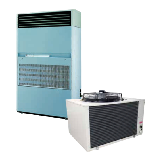
Packaged Air Conditioners
air cooled: X AR / X ARV
Centrales Autonomes de Climatisation
à condensation par air: X AR / X ARV
Zentralklimageräte
luftkühlung: X AR / X ARV
Centrali Autonome di Climatizzazione
con raffreddamento ad aria: X AR / X ARV
Centrales Autónomas de Climatisación
con condensación por aire: X AR / X ARV
IOM X 01-N-
IOM X 01-N-4
Part number / Code / Teil Nummer / Codice / Código : 3990527
Part number / Code / Teil Nummer / Codice / Código : 3990527
Supersedes / Annule et remplace / Annulliert und ersetzt /
Supersedes / Annule et remplace / Annulliert und ersetzt /
Annulla e sostituisce / Anula y sustituye : IOM X 01-N-3
Annulla e sostituisce / Anula y sustituye : IOM X
Français
ALL
01-N-3ALL
UC
Deutsch
Italiano
water cooled: X AO
à condensation par eau: X AO
wasserkühlung: X AO
con raffreddamento ad acqua: X AO
con condensación por agua: X AO
33
54
Español
Publicité
Chapitres
Table des Matières

Manuels Connexes pour Airwell X 1100


Sommaire des Matières pour Airwell X 1100
-
Page 3: Installation Instruction
INSTALLATION INSTRUCTION NOTICE D’INSTALLATION INSTALLATIONSHANDBUCH ISTRUZIONI INSTALLAZIONE INSTRUCCIONES DE INSTALACIÓN... -
Page 19: Installation Instruction
INSTALLATION INSTRUCTION NOTICE D’INSTALLATION INSTALLATIONSHANDBUCH ISTRUZIONI INSTALLAZIONE INSTRUCCIONES DE INSTALACIÓN... - Page 20 SOMMAIRE RECOMMANDATIONS GENERALES ......................3 CONSEILS DE SECURITE................................3 AVERTISSEMENT ..................................3 DONNEES DE SECURITE DU MATERIEL ............................. 4 CONTRÔLE ET STOCKAGE ........................5 GARANTIE ..............................5 COMPOSITION DU COLIS .........................6 DIMENSIONS ............................6 POIDS ..................................... 6 SPECIFICATIONS TECHNIQUES .........................7 ALIMENTATION ELECTRIQUE ..............................7 LIAISON AVEC UNITÉ...
-
Page 21: Recommandations Generales
MISE HORS TENSION OBLIGATOIRE AVANT TOUTES INTERVENTIONS DANS LES BOITIERS ELECTRIQUES RECOMMANDATIONS GENERALES Lire attentivement les consignes de sécurité suivantes avant l’installation de l’appareil. CONSEILS DE SECURITE Lorsque vous intervenez sur votre matériel, suivez les règles de sécurité en vigueur. L’installation, l’utilisation et l’entretien doivent être exécutés par du personnel qualifié... -
Page 22: Donnees De Securite Du Materiel
DONNEES DE SECURITE DU MATERIEL Données sur la sécurité R407C Degré de toxicité Bas. En contact avec la peau Des éclaboussures ou une projection de fluide frigorigène peuvent causer des brûlures mais ne sont pas dangereuses en cas d’absorption. Dégeler les zones affectées avec de l’eau. Enlever les vêtements contaminés avec soin car ils peuvent coller à la peau en cas de brûlures dues au gel. -
Page 23: Contrôle Et Stockage
CONTRÔLE ET STOCKAGE A la réception de l’équipement, vérifier soigneusement tous les éléments en se référant au bordereau de transport afin de s’assurer que toutes les caisses et tous les cartons ont été reçus. Contrôler tous les appareils pour rechercher les dommages visibles ou cachés. -
Page 24: Composition Du Colis
COMPOSITION DU COLIS X 1100 / X 1900 1 unité intérieure 1 schéma électrique 1 légende 1 lot de passe-fils UC 34 / UC 54 1 unité extérieure DIMENSIONS 1100 1540 1900 1735 1000 POIDS X ARV X AO 1100... -
Page 25: Specifications Techniques
SPECIFICATIONS TECHNIQUES ALIMENTATION ELECTRIQUE 1100 1900 Type d’alimentation 3 ~230 V* - 50 Hz 3N ~400 V - 50 Hz 3 ~230 V* - 50 Hz 3N ~400 V - 50 Hz Modèles X AR X AO X AR X AO X ARV X AO X ARV... -
Page 26: Description
DESCRIPTION 1. Câble circuit de commande - cas alimentation générale en Tri 400V. sans Neutre. 2. Câble pour rappel de commande (accessoire). 3. Liaisons électriques vers l'UC. 4. Câble d'alimentation générale. 5. Evacuation des condensats par tube souple Ø 20 x 25. 6. -
Page 27: Positionnement De L'unite
POSITIONNEMENT DE L’UNITE Le support de l'unité devra être prévu tel qu'indiqué dans ce manuel. Dans le cas d'un support inapproprié le personnel court un risque de dommages corporels. L’unité doit être installée sur une fondation horizontale stable, suffisamment robuste pour supporter son poids en utilisation. -
Page 28: Diffusion Et Reprise D'air
DIFFUSION ET REPRISE D’AIR 1. Reprise directe par le panneau avant amovi ble A et le filtre D (montage d’origine), 2. Reprise totale arrière par gaine : Eléments de raccordements de gaine E à monter à l’arrière de l’appareil (Déposer la tôle de bouchage J). -
Page 29: Installation De L'unite Exterieure)
INSTALLATION DE L’UNITE EXTERIEURE) Placer le condenseur à AIR à l’extérieur, dans un endroit non accessible au public et dans une atmosphère non polluée (fumée, acide etc ... ). DÉGAGEMENTS À PRÉVOIR. Respecter les cotes mini indiquées pour un fonctionnement correct et pour éviter le recy clage de l’air, même partiel, entre l’aspiration et le soufflage de l’air. -
Page 30: Tube A Realiser Sur Le Chantier
LIAISONS FRIGORIFIQUES Livrées préchargées d’usine LONGUEUR MAXI 25M. Réalisées sur le chantier par l’installateur LONGUEUR MAXI 45M. CHARGE FRIGORIFIQUE liaisons jusqu’à 25m: Ligne GAZ: précharge gazeuse (tube Ø1/2") Ligne LIQUIDE (au-dessus de 2m): 55 g/m (tube Ø 3/8") Pour des liaisons frigorifiques d’une longueur comprise entre 25 et 45m (à réaliser sur le chantier) la détermination des diamètres, de la charge. -
Page 31: Couple De Serrage Des Vannes Frigorifiques
COUPLE DE SERRAGE DES VANNES FRIGORIFIQUES LIQUIDE: ASPIRATION: (petite vanne) 15Nm (grosse vanne) 55Nm 1 Newton-mètre = 0,1 mètre-kilo CONSIGNES DE RACCORDEMENT DES VANNES A MEMBRANE CREVABLE (NON DEBROCHABLES) S’assurer de l’alignement rigoureux des deux 1/2 corps de chacune des vannes Enlever les bouchons de protection vissés sur chaque 1/2 corps de vannes . -
Page 32: Raccordements Électriques
RACCORDEMENTS ÉLECTRIQUES Le coffret électrique est situé derrière le pan neau avant inférieur. Les raccordements électriques s’effectuent sur la réglette située dans le coffret. ATTENTION Dans le cas d’une résistance de carter. elle doit être mise en oeuvre en fonction de la température ambiante dans laquelle se trouve le compresseur : 2 heures avant commuta tion de l’appareil dans une ambiance de 10°C et 4 heures avant dans une ambiance de 0°C. -
Page 33: Liaisons Electriques
LIAISONS ELECTRIQUES ~230 V - 50 Hz LIAISONS AVEC COMMANDE A DISTANCE 1100 1900 FROID+VENTILATION (VS) Intensité nominale Intensité maximale Intensité totale démarrage Section cable mm² 4 x 1.5 4 x 1.5 CHAUD+VENTILATION (VS) Intensité nominale Intensité maximale Intensité totale démarrage Section cable mm²... -
Page 34: Platine De Commande
PLATINE DE COMMANDE 1. Interrupteur Marche/Arrêt ventilation 0 Arrêt 1 Marche avec voyant lumineux NOTA: 2. Sélecteur froid Avec le thermostat froid/chaud automatique à 0 Arrêt zone neutre livré avec la batterie de chauffage électrique incorporée, le fonctionnement 1 Marche froid automatique est obtenu en placant les 2 3. -
Page 35: Installation Instruction
INSTALLATION INSTRUCTION NOTICE D’INSTALLATION INSTALLATIONSHANDBUCH ISTRUZIONI INSTALLAZIONE INSTRUCCIONES DE INSTALACIÓN... - Page 51 INSTALLATION INSTRUCTION NOTICE D’INSTALLATION INSTALLATIONSHANDBUCH ISTRUZIONI INSTALLAZIONE INSTRUCCIONES DE INSTALACIÓN...
- Page 67 INSTALLATION INSTRUCTION NOTICE D’INSTALLATION INSTALLATIONSHANDBUCH ISTRUZIONI INSTALLAZIONE INSTRUCCIONES DE INSTALACIÓN...