
Manuels Connexes pour Autosen AS001

Sommaire des Matières pour Autosen AS001
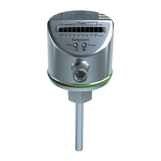
- Page 1 Bedienungsanleitung Strömungswächter Operating instructions Flow monitor Notice d'utilisation Capteur de débit AS001 autosen...
-
Page 2: Table Des Matières
Inhalt 1 Vorbemerkung �����������������������������������������������������������������������������������������������������3 1�1 Zeichenerklärung �������������������������������������������������������������������������������������������3 2 Sicherheitshinweise ���������������������������������������������������������������������������������������������4 3 Bestimmungsgemäße Verwendung ���������������������������������������������������������������������4 3�1 Einsatzbereich ����������������������������������������������������������������������������������������������4 3�2 Funktionsweise Strömungsüberwachung ������������������������������������������������������4 3�3 Funktionsweise Temperaturüberwachung �����������������������������������������������������5 4 Montage ���������������������������������������������������������������������������������������������������������������6 4�1 Montageort ����������������������������������������������������������������������������������������������������6 4�2 Störeinflüsse im Leitungssystem �������������������������������������������������������������������7 4�3 Montagevorgang ��������������������������������������������������������������������������������������������7 5 Elektrischer Anschluss �����������������������������������������������������������������������������������������8 6 Bedien- und Anzeigeelemente �����������������������������������������������������������������������������9 7 Parametieren �������������������������������������������������������������������������������������������������������9 7�1 IO-Link �����������������������������������������������������������������������������������������������������������9... -
Page 3: Vorbemerkung
9 Fehlerbehebung�������������������������������������������������������������������������������������������������16 10 Wartung �����������������������������������������������������������������������������������������������������������17 11 Technische Daten ��������������������������������������������������������������������������������������������17 1 Vorbemerkung 1.1 Zeichenerklärung ► Handlungsanweisung > Reaktion, Ergebnis → Querverweis Wichtiger Hinweis Fehlfunktionen oder Störungen sind bei Nichtbeachtung möglich� Information Ergänzender Hinweis� LED leuchtet grün LED leuchtet orange LED leuchtet rot LED blinkt... -
Page 4: Sicherheitshinweise
2 Sicherheitshinweise • Lesen Sie vor der Inbetriebnahme des Gerätes dieses Dokument� Vergewis- sern Sie sich, dass sich das Produkt uneingeschränkt für die betreffenden Applikationen eignet� • Die Missachtung von Anwendungshinweisen oder technischen Angaben kann zu Sach- und/oder Personenschäden führen� • Unsachgemäßer oder nicht bestimmungsgemäßer Gebrauch kann zu Funk- tionsstörungen des Gerätes oder zu unerwünschten Auswirkungen in Ihrer Applikation führen�... -
Page 5: 3�3 Funktionsweise Temperaturüberwachung
• Steigt die Strömungsgeschwindigkeit, ändert sich der Schaltzustand bei Errei- chen des Schaltpunkts� • Sinkt die Strömungsgeschwindigkeit wieder, ändert sich der Schaltzustand, wenn der Wert "SP minus Hysterese" erreicht ist� Die Hysterese verändert sich mit der Strömungsgeschwindigkeit und sie wird wesentlich beeinflusst vom eingestellten Erfassungsbereich�... -
Page 6: Montage
4 Montage Durch Prozessadapter ist das Gerät adaptierbar an unterschiedliche Prozessan- schlüsse� • Adapter sind gesondert als Zubehör zu bestellen� 4.1 Montageort Generell • Die Sensorspitze soll vollständig vom Medium umflossen werden� • Eintauchtiefe des Messfühlers: minde- stens 12 mm� Empfohlen • Bei waagerecht verlaufenden Rohren: Montage seitlich�... -
Page 7: 4�2 Störeinflüsse Im Leitungssystem
4.2 Störeinflüsse im Leitungssystem Einbauten in der Rohrleitung, Krümmungen, Ventile, Reduzierungen u� ä� führen zu Verwirbelungen des Mediums� Dies beeinträchtigt die Funktion des Geräts� Empfehlung: Abstände einhalten zwischen Sensor und Störeinflüssen: 5...10 x D 3...5 x D Flow High Flow High 0 1 2 3 4 5 6 7 8 9 0 1 2 3 4 5 6 7 8 9... -
Page 8: Elektrischer Anschluss
5 Elektrischer Anschluss Das Gerät darf nur von einer Elektrofachkraft installiert werden� Befolgen Sie die nationalen und internationalen Vorschriften zur Errichtung elektrotechnischer Anlagen� Spannungsversorgung nach EN 50178, SELV, PELV� ► Anlage spannungsfrei schalten� ► Gerät folgendermaßen anschließen: OUT2 OUT1 Pin 1 • OUT2 (PNP): Schaltsignal für Temperaturüberwachung Pin 2 • Programmierleitung für Fernabgleich... -
Page 9: Bedien- Und Anzeigeelemente
6 Bedien- und Anzeigeelemente Flow High 0 1 2 3 4 5 6 7 8 [x10°C] Setpoint Flow Temp 1: Betriebsanzeige • Die grünen LEDs zeigen die aktuelle Strömung (die LEDs 0 bis 9 repräsentieren den Bereich zwischen Strömungsstillstand und Maximalströmung)� • Eine leuchtende LED zeigt die Position des Schaltpunkts Strömung (SP1) (orange = Ausgang geschlossen, rot = Ausgang offen)�... -
Page 10: 7�1�2 Gerätespezifische Informationen
7.1.2 Gerätespezifische Informationen Die zur Konfiguration des IO-Link-Gerätes notwendigen IODDs sowie detaillierte Informationen über Prozessdatenaufbau, Diagnoseinformationen und Parameter- adressen finden Sie unter www�autosen�com 7.1.3 Parametrierwerkzeuge Alle notwendigen Informationen zur benötigten IO-Link-Hardware und Software finden Sie unter www�autosen�com Einstellbare Parameter SP1 / rP1 Oberer / Unterer Grenzwert für Durchfluss, bei dem OUT1 schaltet... -
Page 11: 7�3 Schaltpunkt Sp1 Für Strömung Verändern (Optional)
Normalströmung unterschreitet den Darstel- lungsbereich des Displays� Flow High 2 Einstellmöglichkeiten: ► Schaltpunkt verändern (→ 7.3). 0 1 2 3 4 5 6 7 8 [x10°C] ► High Flow-Abgleich durchführen (→ 7.4). Normalströmung überschreitet den Darstel- Flow High lungsbereich des Displays (LED 9 blinkt)� ► High Flow-Abgleich durchführen (→ 7.4). 0 1 2 3 4 5 6 7 8 [x10°C] Sie können die Werkseinstellung jederzeit wieder herstellen (→ 7.8). -
Page 12: 7�5 Schaltpunkt Sp2 Für Temperatur Einstellen
► Taste loslassen� Damit ist das Gerät an die Strömungsverhältnisse angepasst� Es geht in den Betriebsmodus, das Display sollte nun Beispiel 1 zeigen� Der Abgleich beeinflusst den Schaltpunkt: Er wird proportional erhöht (maximal bis auf LED 7)� 7.5 Schaltpunkt SP2 für Temperatur einstellen ►... -
Page 13: 7�6 Low Flow-Abgleich (Optional)
0 1 2 3 4 5 6 7 8 0 1 2 3 4 5 6 7 8 [x10°C] [x10°C] Nach Erreichen der LED 0 beginnt der Durchlauf der blinkenden LED wieder bei LED 9; die stetig leuchtende LED (Zehnerstelle) wandert eine Position nach links (wenn eingestellt wird mit )�... -
Page 14: 7�8 Werkseinstellung Wieder Herstellen (Reset)
> Nach 10 s wird die aktuelle Einstellung angezeigt: LEDs 5���9 leuchten orange (= Ausgänge in Schließerfunktion)� > Nach ca� 15 s blinken LEDs 0���4 orange� ► Taste loslassen� Die Ausgänge sind umgestellt auf Öffnerfunktion� Für erneute Umstellung: Vorgang wiederholen� Mit einem IO-Link-fähigen Parametriertool ist es möglich, die Ausgänge getrennt als Öffner oder Schließer zu konfigurieren�... -
Page 15: Betrieb
8 Betrieb Nach jedem Einschalten der Versorgungsspannung leuchten alle LEDs auf und verlöschen wieder schrittweise (während dieser Zeit sind die Ausgänge geschlos- sen, wenn sie als Schließer konfiguriert sind)� Danach ist das Gerät betriebsbereit� Bei Ausfall oder Unterbrechung der Betriebsspannung bleiben alle Einstellungen erhalten�... - Page 16 8.3 Störanzeigen Kurzschluss an Schaltausgang OUT1 Betriebsanzeige und 5 rote LEDs links leuchten 0 1 2 3 4 5 6 7 8 [x10°C] im Wechsel� Ist der Kurzschluss behoben, geht das Gerät sofort 0 1 2 3 4 5 6 7 8 [x10°C] wieder in den normalen Betriebszustand�...
- Page 17 ► Sensorspitze von Zeit zu Zeit auf Ablagerungen überprüfen� ► Mit einem weichen Tuch reinigen� Fest anhaftende Ablagerungen (z� B� Kalk) lassen sich mit handelsüblichem Essigreiniger entfernen� 11 Technische Daten Technische Daten und Maßzeichung unter www�autosen�com� Weitere Informationen unter www�autosen�com...
- Page 18 Contents 1 Preliminary note �������������������������������������������������������������������������������������������������19 1�1 Explanation of symbols ��������������������������������������������������������������������������������19 2 Safety instructions ���������������������������������������������������������������������������������������������20 3 Functions and features ��������������������������������������������������������������������������������������20 3�1 Applications ������������������������������������������������������������������������������������������������20 3�2 Operating principle flow monitoring �������������������������������������������������������������20 3�3 Operating principle temperature monitoring ������������������������������������������������21 4 Installation����������������������������������������������������������������������������������������������������������22 4�1 Installation location ��������������������������������������������������������������������������������������22 4�2 Interference in the pipe system �������������������������������������������������������������������23 4�3 Installation procedure ����������������������������������������������������������������������������������23 5 Electrical connection ������������������������������������������������������������������������������������������24...
-
Page 19: Preliminary Note
9 Troubleshooting �������������������������������������������������������������������������������������������������32 10 Maintenance ����������������������������������������������������������������������������������������������������33 11 Technical data ��������������������������������������������������������������������������������������������������33 1 Preliminary note 1.1 Explanation of symbols ► Instructions > Reaction, result → Cross-reference Important note Non-compliance can result in malfunction or interference� Information Supplementary note� LED lights green LED lights orange LED lights red LED flashes... -
Page 20: Safety Instructions
2 Safety instructions • Please read this document prior to set-up of the unit� Ensure that the product is suitable for your application without any restrictions� • If the operating instructions or the technical data are not adhered to, personal injury and/or damage to property can occur�... -
Page 21: 3�3 Operating Principle Temperature Monitoring
The hysteresis changes with the flow speed and it is essentially influenced by the set monitoring range� It is 2���5 cm/s for the setting 5���100 cm/s (= factory setting), it increases with higher flow speeds� • The typical response time of the unit is 1���10 s� It can be influenced by the switch point: - Low switch point = quick reaction with rising flow�... -
Page 22: Installation
4 Installation Using process adapters the unit can be adapted to different process connections� • Adapters have to be ordered separately as accessories� 4.1 Installation location General • The sensor tip is to be completely surrounded by the medium� • Immersion depth of the sensor: mini- mum 12 mm�... -
Page 23: 4�2 Interference In The Pipe System
4.2 Interference in the pipe system Components integrated in the pipes, bends, valves, reductions, etc� lead to turbu- lence of the medium� This affects the function of the unit� Recommendation: Adhere to the distances between sensor and sources of inter- ference: 5...10 x D 3...5 x D... -
Page 24: Electrical Connection
5 Electrical connection The unit must be connected by a qualified electrician� The national and international regulations for the installation of electrical equipment must be adhered to� Voltage supply according to EN 50178, SELV, PELV� ► Disconnect power� ► Connect the unit as follows: OUT2 OUT1 Pin 1... -
Page 25: Operating And Display Elements
6 Operating and display elements Flow High 0 1 2 3 4 5 6 7 8 [x10°C] Setpoint Flow Temp 1: Operation indication • The green LEDs indicate the current flow (LEDs 0 to 9 represent the range between flow standstill and maximum flow)� • A lit LED indicates the position of the switch point flow (SP1) (orange = output closed, red = output open)�... -
Page 26: 7�1�2 Device-Specific Information
You will find the IODDs necessary for the configuration of the IO-Link unit and detailed information about process data structure, diagnostic information and parameter addresses at www�autosen�com� 7.1.3 Parameter setting tools You will find all necessary information about the required IO-Link hardware and software at www�autosen�com�... -
Page 27: 7�3 Change Switch Point Sp1 For Flow (Optional)
Your normal flow is below the representation range of the display� Flow High 2 setting options: ► Change the switch point (→ 7.3). 0 1 2 3 4 5 6 7 8 [x10°C] ► Carry out high-flow adjustment (→ 7.4). Your normal flow exceeds the representation Flow High range of the display (LED 9 flashes)� ►... -
Page 28: 7�5 Set Switch Point Sp2 For Temperature
The unit is now adapted to your flow conditions� It returns to the operating mode, the display should now show example 1� The adjustment affects the switch point: it is increased proportionally (maxi- mum up to LED 7)� 7.5 Set switch point SP2 for temperature ►... -
Page 29: 7�6 Low-Flow Adjustment (Optional)
After LED 0 has been reached the cycle of the flashing LED starts again at LED 9; the continuously lit LED (tens digit) moves one position to the left (when setting is made with )� 0 1 2 3 4 5 6 7 8 [x10°C] 0 1 2 3 4 5 6 7 8 [x10°C]... -
Page 30: 7�8 Restore The Factory Setting (Reset)
Using an IO-Link capable parameter setting tool, the outputs can be sepa- rately set as normally closed or normally open� 7.8 Restore the factory setting (reset) ► Press for at least 15 s� > LED 9 lights, after approx� 5 s it flashes� >... -
Page 31: Operation
8 Operation After every power on all LEDs light and go out again step by step (during this time the outputs are closed if configured as normally open)� The unit is then ready for operation� In case of power failure or interruption all settings remain� 8.1 Display current temperature and switch point SP2 ►... -
Page 32: 8�3 Interference Indicators
8.3 Interference indicators Short circuit at switching output OUT1� The operating indicator and 5 red LEDs on the left light alternately� 0 1 2 3 4 5 6 7 8 [x10°C] If the short circuit has been rectified, the unit imme- 0 1 2 3 4 5 6 7 8 [x10°C] diately passes into the normal operating state�... - Page 33 ► Check the sensor tip for build-up from time to time� ► Clean it using a soft cloth� Stubborn build-up (e�g� lime) can be removed using a common vinegar cleaning agent� 11 Technical data Technical data and scale drawing at www�autosen�com� More information at www�autosen�com...
- Page 34 Contenu 1 Remarques préliminaires �����������������������������������������������������������������������������������35 1�1 Explication des symboles ����������������������������������������������������������������������������35 2 Consignes de sécurité ���������������������������������������������������������������������������������������36 3 Fonctionnement et caractéristiques �������������������������������������������������������������������36 3�1 Application ��������������������������������������������������������������������������������������������������36 3�2 Fonctionnement surveillance du débit ���������������������������������������������������������36 3�3 Principe de fonctionnement surveillance de température ����������������������������37 4 Montage �������������������������������������������������������������������������������������������������������������38 4�1 Lieu de montage ������������������������������������������������������������������������������������������38 4�2 Parasites dans la conduite ��������������������������������������������������������������������������39 4�3 Montage �������������������������������������������������������������������������������������������������������39...
-
Page 35: Remarques Préliminaires
9 Correction de défauts ����������������������������������������������������������������������������������������48 10 Entretien ����������������������������������������������������������������������������������������������������������49 11 Données techniques ����������������������������������������������������������������������������������������49 1 Remarques préliminaires 1.1 Explication des symboles ► Action à faire > Retour d'information, résultat → Référence croisée Remarque importante Le non-respect peut aboutir à des dysfonctionnements ou perturbations� Information Remarque supplémentaire�... -
Page 36: Consignes De Sécurité
2 Consignes de sécurité • Lire cette notice avant la mise en service de l'appareil� S'assurer que le produit est approprié pour l'application concernée sans aucune restriction d'utilisation� • Le non-respect des consignes ou des données techniques peut provoquer des dommages matériels et/ou corporels�... -
Page 37: 3�3 Principe De Fonctionnement Surveillance De Température
• Si la vitesse du fluide diminue de nouveau, l'état de commutation change quand la valeur " SP moins l'hystérésis " est atteinte� L'hystérésis change en fonction de la vitesse et dépend considérablement de la zone de détection réglée� Elle est de 2���5 cm/s pour le réglage 5���100 cm/s (= réglage usine), elle aug- mente en cas de vitesses plus élevées�... -
Page 38: Montage
4 Montage L'adaptateur process permet le raccordement de l'appareil à différents raccords process� • Les adaptateurs sont à commander séparément comme accessoires� 4.1 Lieu de montage En général • Le bout de la sonde doit être complète- ment couvert par le fluide� • Profondeur d'installation de la sonde : min�... -
Page 39: 4�2 Parasites Dans La Conduite
4.2 Parasites dans la conduite Des éléments présents dans le tube, des coudes, des vannes, des réductions de diamètre et d'autres choses semblables mènent à des perturbations du fluide� Ceci affecte le fonctionnement de l'appareil� Recommandation : respecter des distances entre le capteur et les perturbations : 5...10 x D 3...5 x D Flow... -
Page 40: Raccordement Électrique
5 Raccordement électrique L'appareil doit être monté par un électricien qualifié� Les règlements nationaux et internationaux relatifs à l'installation de matéri- el électrique doivent être respectés� Alimentation en tension selon EN 50178, TBTS, TBTP� ► Mettre l'installation hors tension� ► Raccorder l'appareil comme suit : OUT2 OUT1 Broche 1... -
Page 41: Eléments De Service Et D'indication
6 Eléments de service et d'indication Flow High 0 1 2 3 4 5 6 7 8 [x10°C] Setpoint Flow Temp 1: Affichage de fonctionnement • Les LED vertes indiquent le débit actuel (les LED 0 à 9 représentent la gamme entre l'arrêt du débit et le débit maximal)�... -
Page 42: 7�1�2 Informations Spécifiques À L'appareil
Vous trouverez les IODD nécessaires pour la configuration de l'appareil IO-Link ansi que des informations détaillées concernant la structure des données process, des informations de diagnostic et les adresses des paramètres sur www�autosen�com� 7.1.3 Outils de paramétrage Vous trouverez toutes les informations nécessaires concernant le matériel et logiciel IO-Link sur www�autosen�com�... -
Page 43: 7�3 Changer Le Seuil De Commutation Sp1 Pour Le Débit (Option)
Le réglage usine est approprié pour Flow High l'application� ► Pour la surveillance du débit un autre 0 1 2 3 4 5 6 7 8 [x10°C] réglage n'est pas nécessaire� Le débit normal est en dessous de la zone d'affichage�... -
Page 44: 7�5 Régler Le Seuil De Commutation Sp2 Pour La Température
► Activer le débit normal dans l'installation� ► Appuyer sur le bouton et le maintenir appuyé� > LED 9 s'allume, après env� 5 s elle clignote� ► Relâcher le bouton� Ceci est l'adaptation optimale de l'appareil aux conditions de débit� Il passe en mode de fonctionnement, l'afficheur devrait maintenant indiquer l'exemple 1�... -
Page 45: 7�6 Réglage Au Débit Minimum (Option)
Si la LED 9 est atteinte, le cycle recommence à la LED 0 ; la LED allumée en permanence (1ère position) est décalée d'une position vers la droite (en cas de réglage par )� 0 1 2 3 4 5 6 7 8 0 1 2 3 4 5 6 7 8 [x10°C] [x10°C]... -
Page 46: 7�8 Récupérer Les Réglages De Base Effectués En Usine (Reset)
> LED 0 s'allume, après env� 5 s elle clignote� > Après 10 s, le réglage actuel est affiché : les LED 5���9 sont allumées en oran- ge (= sorties en fonction normalement ouvert)� > Après env� 15 s les LED 0���4 clignotent en orange� ►... -
Page 47: Fonctionnement
Cette fonction ne peut être réglée qu'à l'aide d'un logiciel de paramétrage et ne peut pas être réglée directement sur l'appareil� 8 Fonctionnement Après chaque mise sous tension, toutes les LED s'allument et s'éteignent de nouveau pas à pas (pendant ce temps, les sorties sont fermées si configurées en fonction normalement ouvert)�... -
Page 48: 8�3 Indication De Défauts
LED 0 clignote : débit actuel bien en dessous de la zone d'affichage� 0 1 2 3 4 5 6 7 8 [x10°C] 8.3 Indication de défauts Court-circuit sur la sortie de commutation OUT1 L'affichage de fonctionnement et les 5 LED rouges 0 1 2 3 4 5 6 7 8 [x10°C] à... - Page 49 ► Vérifier périodiquement la présence éventuelle de dépôts en bout de sonde� ► Nettoyer avec un chiffon doux� Des dépôts adhérents (p�ex� chaux) peuvent être enlevés avec un produit acétique de nettoyage usuel� 11 Données techniques Données techniques et schéma d'encombrement sur www�autosen�com� Plus d'informations à www�autosen�com...
- Page 52 Technische Daten und weitere Informationen unter: Données techniques et informations supplémentaires sur notre site web à: Technical data and further information at: www.autosen.com...