AERMEC MODUCONTROL Manuel D'utilisation
Masquer les pouces Voir aussi pour MODUCONTROL:
Table des Matières

Publicité

Les langues disponibles
  • FR

Les langues disponibles

Liens rapides

REGOLAZIONE ELETTRONICA • ELECTRONIC REGULATION • REGLAGE ELECTRONIQUE
ELEKTRISCHE REGELVORRICHTUNG • REGULACIÓN ELÉCTRICA
MANUALE USO • USAGE MANUAL • MANUEL D'UTILISATION
BEDIENUNGSANLEITUNG • MANUAL DE INSTRUCCIONES
MODUCONTROL
IT
EN
FR
DE
ES
pag 108
pag 143
pag 3
pag 38
pag 73
IMDCFJ. 12.04 6343841_02

Publicité

Table des Matières
loading

Sommaire des Matières pour AERMEC MODUCONTROL

  • Page 1 REGOLAZIONE ELETTRONICA • ELECTRONIC REGULATION • REGLAGE ELECTRONIQUE ELEKTRISCHE REGELVORRICHTUNG • REGULACIÓN ELÉCTRICA MANUALE USO • USAGE MANUAL • MANUEL D’UTILISATION BEDIENUNGSANLEITUNG • MANUAL DE INSTRUCCIONES MODUCONTROL pag 108 pag 143 pag 3 pag 38 pag 73 IMDCFJ. 12.04 6343841_02...
  • Page 3: Dichiarazione Di Conformità Ce

    AERMEC S.p.A. I-37040 Bevilacqua (VR) Italia – Via Roma, 996 Tel. (+39) 0442 633111 Telefax 0442 93730 – (+39) 0442 93566 www.aermec.com - info@aermec.com MODUCONTROL NUMERO DI SERIE DICHIARAZIONE Noi, firmatari della presente, dichiariamo sotto la nostra esclusiva responsabilità che l'insieme in oggetto così...
  • Page 4: Table Des Matières

    Settaggi default RESISTENZA ................... 9 Settaggi default MENÚ INSTALLATORE ................. 10 Settaggi default MENÚ INSTALLATORE 2 ..............12 Configurazioni unità con MODUCONTROL ..............13 Visualizzazioni interfaccia utente e parametri ............... 14 Menù letture ........................15 Menù LETTURE AVANZATE .................... 16 Menù...
  • Page 5 Impostazione resistenza integrazione o attivazione caldaia ........23 Configurazione controllo pannello ................23 Abilitazione acqua sanitaria ..................23 Potenza dedicata alla produzione acqua sanitaria ........... 24 Tempo attesa in Ingresso/uscita ................24 Tempo attesa in Ingresso/uscita ................24 Abilitazione by-pass flussostato ................24 Tempo by-pass flussostato ..................
  • Page 6: Precauzioni E Norme Di Sicurezza

    La garanzia dell'apparecchio non copre in ogni caso i costi dovuti ad autoscale, ponteggi o altri sistemi di elevazione che si rendessero necessari per effettuare gli interventi in garanzia. AERMEC S.p.A. declina ogni responsabilità per qualsiasi danno dovuto ad un uso improprio della macchina, ad una lettura parziale o superfi ciale delle informazioni contenute in questo manuale.
  • Page 7: Caratteristiche Della Regolazione

    Scheda interfaccia protocollo ModBus Accessorio Modu_485A ATTENZIONE: nel caso si desideri implementare un sistema di gestione BMS, è disponibile sul nostro sito www.aermec.com un manuale con tutte le specifi che necessarie alla realizzazzione di un sistema di supervisione seriale. IMDCFJ. 12.05 6343841_03...
  • Page 8: Settaggi Default Menú Utente

    Settaggi default MENÚ UTENTE Parametri Menù UTENTE - (Password 000) Presente sulle unità Stringa parametro Indice parametro ANLI SRPV1 Unità in grado di produrre acqua calda (pompa di calore o unità solo caldo) Unità in grado di produrre acqua fredda (pompa di calore reversibile o unità solo freddo) Tutte le unità...
  • Page 9: Settaggi Default Resistenza

    Settaggi default RESISTENZA Parametri Menù RESISTENZA - (Password 001) Presente sulle unità Stringa parametro Indice parametro ANLI SRPV1 Unità in grado di produrre acqua calda (pompa di calore o unità solo caldo), in cui è prevista una resistenza elettrica integrativa Tutte le unità...
  • Page 10: Settaggi Default Menú Installatore

    Settaggi default MENÚ INSTALLATORE Parametri Menù INSTALLATORE - (Password 030) Presente sulle unità Stringa parametro Indice parametro ANLI SRPV1 Unità in grado di produrre acqua calda (pompa di calore o unità solo caldo) Unità in grado di produrre acqua fredda (pompa di calore reversibile o unità solo freddo) Tutte le unità...
  • Page 11 Parametri Menù INSTALLATORE - (Password 030) Presente sulle unità Stringa parametro Indice parametro ANLI SRPV1 Unità in grado di produrre acqua calda (pompa di calore o unità solo caldo) Tutte le unità (sia pompe di calore, solo caldo o solo freddo) Unità...
  • Page 12: Settaggi Default Menú Installatore 2

    Settaggi default MENÚ INSTALLATORE 2 Parametri Menù INSTALLATORE 2 - (Password 031) Presente sulle unità Indice parametro ANLI SRPV1 Unità in grado di produrre acqua calda (pompa di calore o unità solo caldo) Tutte le unità (sia pompe di calore, solo caldo o solo freddo) Funzioni relative ai parametri del Menù...
  • Page 13: Configurazioni Unità Con Moducontrol

    Configurazioni unità con MODUCONTROL Configurazioni disponibili per ogni unità Solo le taglie: ✔ ✘ ✘ ✘ ✔ 100, 150, 200 Solo le taglie: ✔ ✔ ✔ ✘ ✔ ANL H 100, 150, 200 ✔ ✔ ✔ ✘ ✔ ✔ ANLI ✔...
  • Page 14: Visualizzazioni Interfaccia Utente E Parametri

    Visualizzazioni interfaccia utente e parametri L’interfaccia utente principale è rappresentata da un pannello a led con tastiera capacitiva (ovvero con tasti a sfi oramento); le visualizzazioni sono organizzate tramite tre menù: • Menù LETTURE (tasto (C) Fig.1) Contiene le informazioni (in sola visualizzazione) sul funzio- namento corrente dell’unità.
  • Page 15: Menù Letture

    Menù letture Per entrare nel menù letture premere il alla lettura stessa. Per passare alla let- primo secondo la stringa per identifi ca- tasto in (Fig.4); una volta entrati nel menù tura successiva è necessario premere re la lettura in corso (è tuttavia possibile letture, sul display viene visualizzato l’in- il tasto in (Fig.5), mentre per tornare a identifi...
  • Page 16: Menù Letture Avanzate

    Menù LETTURE AVANZATE Per entrare nel menù LETTURE AVAN- lore delle password usare i tasti freccia. per un secondo, dopo di chè viene ZATE premere il tasto mostrato in Una volta inserita la password corretta sostituita dal valore relativo alla lettura (Fig.7);...
  • Page 17: Menù Utente

    Menù UTENTE Per entrare nel menù UTENTE pre- Una volta inserita la password corretta parametro successivo, usare i tasti frec- mere il tasto mostrato in (Fig.7); una premere il tasto mostrato in (Fig.7). Sul cia (Fig.8). Per modifi care un parame- volta premuto il tasto si dovrà...
  • Page 18: Impostazione Banda Proporzionale A Freddo

    Impostazione banda proporzionale a freddo Valore Valore Indice - stringa Funzione parametro Questo parametro indica la banda proporzionale applicata al set freddo; questa banda comporta un gestione ottimizzata del compressore, accendendolo solo se la temperatura 1 °C 20 °C dell’acqua in ingresso/uscita (in base al tipo di controllo impostato dal parametro (0) nel menù installatore) è...
  • Page 19: Impostazione Set Temperatura A Freddo 1

    Impostazione set temperatura a freddo 1 Valore Valore Indice - stringa Funzione parametro Questo parametro indica il massimo valore del set a freddo, in corrispondenza della minima -20 °C 26 °C temperatura aria esterna (indice (7) menù utente). Questo parametro è visibile solo se è stato attivata la funzione compensazione (indice (5) menù...
  • Page 20: Impostazione Set Caldo 2

    Impostazione set caldo 2 Valore Valore Indice - stringa Funzione parametro Questo parametro indica il minimo valore del set a caldo, in corrispondenza della massima temperatura aria esterna (indice (C) menù utente). Questo parametro è visibile solo se è stato attivata la funzione compensazione (indice (5) menù utente). (*): 25 °C - il limite massimo è...
  • Page 21: Menù Installatore

    Menù INSTALLATORE Per entrare nel menù INSTALLATORE ta premere il tasto mostrato in (Fig.9). i tasti freccia (Fig.10). Per modifi care un premere il tasto mostrato in (Fig.9); Sul display viene visualizzato l’indice parametro basta selezionarlo, premere una volta premuto il tasto si dovrà in- del parametro INSTALLATORE ed una il tasto mostrato in (Fig.9), modifi...
  • Page 22: Impostazione Force-Off A Caldo

    Impostazione FORCE-OFF a caldo Valore Valore Indice - stringa Funzione parametro Le pompe di calore prevedono un controllo sulla temperatura di lavoro (ingresso o uscita) alla 30 °C 70 °C quale viene collegata una soglia di sicurezza oltre la quale viene spento il compressore in maniera immediata ed automatica;...
  • Page 23: Impostazione Resistenza Integrazione O Attivazione Caldaia

    Impostazione resistenza integrazione o attivazione caldaia Valore Valore Indice - stringa Funzione parametro Questo parametro indica quale logica deve essere utilizzata nella gestione della reistenza elettrica integrativa; tale logica è determinata dal valore impostato in questo parametro, quindi in base al valore le impostazioni sono: 0 = Nessuna resistenza integrativa presente sull’unità;...
  • Page 24: Potenza Dedicata Alla Produzione Acqua Sanitaria

    • rappresenta l’allarme pompa (come nella versione software precedente), se il parametro è settato con il valore 3 Si ricorda inoltre che se settiamo questo parametro con il valore 3, rendiamo compatibile la scheda moducontrol con la versione software precedente (3.6). Abilitazione by-pass flussostato Valore...
  • Page 25: Standby Da Temperatura Ambiente Elevata

    Valore Valore Indice - stringa Funzione parametro Questo parametro indica la velocità di comunicazione tra supervisore e moducontrol; tale velocità viene impostata in base al valore selezionato per questo parametro: 0 = 9600 bps 1 = 19200 bps 2= 38400 bps...
  • Page 26: Limite Massimo Set Point A Caldo Impostabile

    Limite temperatura aria 1 Valore Valore Indice - stringa Funzione parametro Questo parametro indica la temperatura dell’aria esterna a cui la macchina può produrre il suo massimo valore di acqua (tale valore è specificato nel parametro P - St1). -25 °C 45°C Limite temperatura acqua 1 Valore...
  • Page 27: Menù Installatore_2

    Menù INSTALLATORE_2 Per entrare nel menù INSTALLATORE_2 seguire la stessa procedura operativa descritta per il menù INSTALLATORE; l’unica modifi ca è il valore della password, tale valore è 31. ATTENZIONE: la modifi ca dei seguen- ti parametri è di esclusiva competen- za del personale qualifi...
  • Page 28: Menù Installatore_3

    Menù INSTALLATORE_3 Per entrare nel menù INSTALLATORE_3 seguire la stessa procedura operativa descritta per il menù INSTALLATORE; l’unica modifi ca è il valore della password, tale valore è 84. ATTENZIONE: la modifi ca dei seguen- ti parametri è di esclusiva competen- za del personale qualifi...
  • Page 29: Gestione Resistenza Elettrica

    Gestione resistenza elettrica Le unità con moducontrol prevedono Logica selezione modalità di gestione resistenza Fig.11 la possibilità di gestire una resistenza elettrica; tale resistenza può essere gestita secondo diverse modalità: • In integrazione (questa modalità Resistenza Resistenza Resistenza prevede un uso contemporaneo della modalità...
  • Page 30: Menù Resistenza

    Menù RESISTENZA Per entrare nel menù RESISTENZA premere il tasto mostrato in (Fig.14). Sul (Fig.15). Per modifi care un parametro premere il tasto mostrato in (Fig.14); display viene visualizzato l’indice del basta selezionarlo, premere il tasto mo- una volta premuto il tasto si dovrà in- parametro RESISTENZA ed una stringa strato in (Fig.14), modifi...
  • Page 31: Impostazione Set Resistenza Integrativa

    Impostazione set resistenza integrativa Valore Valore Indice - stringa Funzione parametro Questo parametro indica la scostamento dal set point caldo, per lo spegnimento della resi- 0 °C 65 °C stenza elettrica (se attiva) nella modalità integrazione; come illustrato nella Fig.12 a pagina precedente (Parametro Sri).
  • Page 32: Tabella Configurazione Dip-Switch

    Si ricorda che alcune delle opzioni gestibili dal pannello sono vincolate ad uno specifi co settaggio di alcuni dip-switch. Dip-switch (A) Impostazioni di default DIP-SWITCH MODUCONTROL DIP-SWITCH DIP-SWITCH (A) Unità ANL H ANL C ANL A/Q...
  • Page 33 Dip-switch N° Dip Stato Funzione Macchina impostata come pompa di calore Macchina impostata come solo freddo Sbrinamento previsto solo per inversione ciclo Sbrinamento per iniezione di gas caldo Acqua glicolata: set antigelo modificabile Set antigelo (Parametro B) bloccato Controllo resa disabilitato Controllo resa abilitato Parzializzazioni di sicurezza disabilitato Parzializzazioni di sicurezza abilitate...
  • Page 34: Tabella Riassuntiva Allarmi

    Tabella riassuntiva allarmi sa maniera dei preallarmi, tranne che per pana permette di visualizzare la lista degli Le unità prevedono due tipologie nella l’accensione della spia rossa fissa. Prima segnalazione di malfunzionamento: allarmi (con indice e causa indicato nella di riarmare l’unità, si consiglia di contattare tabella sottostante).
  • Page 35 Codice Codice Cause Note Allarme Preallarme Questa segnalazione si verifica quando il trasduttore in mandata Trasduttore pressione mandata del compressore risulta assente e la macchina è impostata come compressore assente pompa di calore o è impostata la presenza del DCP Questa segnalazione si verifica quando il trasduttore rileva una pressione di mandata superiore alla soglia di parametro set_fab- Alta pressione...
  • Page 36 Codice Codice Cause Note Allarme Preallarme Sovratemperatura aletta di (cod. APY 1) raffreddamento Sovracorrente in accelerazione Errore hardware (cod. APY 2) Sovracorrente a velocità costante Errore hardware (cod. APY 3) Sovracorrente in decelerazione Errore hardware (cod. APY 4) Sottovoltaggio sul DC Bus (cod.
  • Page 37 Codice Codice Cause Note Allarme Preallarme Guasto sensore temperatura drive Inverter Carel Autoconfigurazione fallita Inverter Carel Drive inverter disabilitato Inverter Carel Errore fasi motore Inverter Carel Ventola di raffreddamento Inverter Carel Inverter guasta Speed fault Inverter Carel Allarme che si verifica con PFC abilitato mentre il bus DC è PFC fault molto basso Questo allarme non sarà...
  • Page 39 Aermec S.p.A. I-37040 Bevilacqua (Verona) Italy – Via Roma, 996 Tel. (+39) 0442 633111 Fax 0442 93730 – (+39) 0442 93566 www.aermec.com - info@aermec.com MODUCONTROL SERIAL NUMBER EC DECLARATION OF We, the undersigned, declare on our own exclusive responsibility that the object in question,...
  • Page 40 ELECTRIC HEATER default settings ................45 INSTALLER MENU default settings ................46 INSTALLER MENU 2 default settings ................48 Unit configurations with MODUCONTROL ..............49 User interface and parameter visualisations ..............50 Readings menu ........................ 51 ADVANCED READINGS menu ..................52 USER menu ........................
  • Page 41 Panel control configuration ..................59 Enabling domestic water ................... 59 Power dedicated to domestic water production ............60 Standby time in Input/Output ..................60 Standby time in Input/Output ..................60 Enabling flow switch bypass ..................60 Time for flow switch bypass ..................60 High room temperature standby ................
  • Page 42: Precautions And Safety Regulations

    AERMEC S.p.A. declines all liability for any damage due to improper use of the machine, or the partial or superfi cial reading of the information contained in this manual.
  • Page 43: Characteristics Of The Regulation

    Accessory PR3 ModBus protocol interface board Modu_485A accessory ATTENTION: If you wish to implement a BMS management system, a manual is available on our site www.aermec.com with all specifications necessary for the realisation of a serial supervision system. IMDCFJ. 12.05 6343841_03...
  • Page 44: User Menu Default Settings

    USER MENU default settings USER menu parameters (Password ) Present on the units String parameter Index parameter ANLI SRPV1 Unit able to produce hot water (heat pump water or heating only unit) Unit able to produce cold water (reversible heat pump water or cooling only unit) All units (heat pumps, heating only or cooling only) Unit that can produce domestic hot water Functions relative to USER parameters...
  • Page 45: Electric Heater Default Settings

    ELECTRIC HEATER default settings Electric Heater menu parameters (Password 001) Present on the units String parameter Index parameter ANLI SRPV1 Unit able to produce hot water (heat pump or heating only unit), in which an integrative electric resist- ance is envisioned All units (heat pumps, heating only or cooling only) Functions relative to Electric Heater parameters Index...
  • Page 46: Installer Menu Default Settings

    INSTALLER MENU default settings INSTALLER menu parameters (Password 030 ) Present on the units String parameter Index parameter ANLI SRPV1 Unit able to produce hot water (heat pump water or heating only unit) Unit able to produce cold water (reversible heat pump water or cooling only unit) All units (heat pumps, heating only or cooling only) Unit that can produce domestic hot water Functions relative to INSTALLER parameters...
  • Page 47 INSTALLER menu parameters (Password 030 ) Present on the units String parameter Index parameter ANLI SRPV1 Unit able to produce hot water (heat pump water or heating only unit) All units (heat pumps, heating only or cooling only) Unit that can produce domestic hot water Functions relative to INSTALLER parameters Index Index...
  • Page 48: Installer Menu 2 Default Settings

    INSTALLER MENU 2 default settings INSTALLER 2 menu parameters - (Password 131) Present on the units Index parameter ANLI SRPV1 Unit able to produce hot water (heat pump water or heating only unit) All units (heat pumps, heating only or cooling only) Functions relative to INSTALLER 2 menu parameters Index Function...
  • Page 49: Unit Configurations With Moducontrol

    Unit configurations with MODUCONTROL Configurations available for every unit Only sizes; ✔ ✘ ✘ ✘ ✔ 100, 150, 200 Only sizes; ✔ ✔ ✔ ✘ ✔ ANL H 100, 150, 200 ✔ ✔ ✔ ✘ ✔ ✔ ANLI ✔ ✔...
  • Page 50: User Interface And Parameter Visualisations

    User interface and parameter visualisations The main user interface is represented by a LED panel with capacitive keyboard (touch keys); the visualisations are ar- ranged in three menus: • READINGS menu (key (C) Fig.1) Containing the information (visualisation mode only) relating to current unit functioning.
  • Page 51: Readings Menu

    Readings menu To access the readings menu, press the reading itself. To move on to the next the current reading (it is possible, howe- key in (Fig.4); once the readings menu reading, press the key in (Fig.5); to go ver, to identify any reading via the value has been accessed, the monitor will back to the previous one, press the key of the indicator, comparing it with the...
  • Page 52: Advanced Readings Menu

    ADVANCED READINGS menu To enter the ADVANCED READINGS the value of the password use the arrow displayed for one second, after which it menu, press the key shown in (Fig.7). keys. Once the correct password has is replaced by the value relative to the Once the key has been pressed the been inserted, press the key shown in reading itself.
  • Page 53: User Menu

    USER menu To access the USER menu, press the password, press the key in (Fig.7). The rameter, just select it, press the key in key in (Fig.7). Once the key has been monitor will show the index of the USER (Fig.7), modify the assigned value using pressed, you must insert the password parameter and a 3-character string that...
  • Page 54: Setting Of Proportional Cooling Band

    Setting of proportional cooling band Index - String Parameter function value value This parameter indicates the proportional band applied to the cooling set; this band produces the opti- mised management of the compressor, only switching it on if the inlet/outlet water temperature (depen- 1 °C 20 °C ding on the type of control set by parameter (0) in the installer menu) is greater than the cooling work...
  • Page 55: Setting Cooling Temperature Setpoint 1

    Setting cooling temperature setpoint 1 Index - String Parameter function value value This parameter indicates the maximum value of the cooling setting, corresponding with the minimum -20 °C 26 °C outside air temperature (index (7) user menu). This parameter is only visible if the compensation fun- ction has been activated (index (5) user menu).
  • Page 56: Setting Heating Set 2

    Setting heating set 2 Value Value Index - string Parameter function This parameter indicates the minimum value set at heating, in correspondence with the maximum outdoor air temperature (user menu index (c) This parameter is visible only if the compensation function is activated (use menu index (5)). 25 °C (*): - the maximum limit can be configured via the parameter (t) of the installer menu;...
  • Page 57: Installer Menu

    INSTALLER menu To access the INSTALLER menu, press key in (Fig.9). The monitor will show the lect it, press the key in (Fig.9), modify the key in (Fig.9). Once the key has been index of the INSTALLER parameter and the assigned value using the arrow keys pressed, you must insert the password a 3-character string that identifi...
  • Page 58: Setting Heating Force-Off

    Setting heating FORCE-OFF Index - String Parameter function value value The heat pumps check the working temperature (input or output), to which a safety threshold is con- 30 °C 70 °C nected, and beyond which the compressor is switched off immediately and automatically; this threshold is called FORCE-OFF.
  • Page 59: Setting The Supplementary Electric Heater Or Activating The Boiler

    Setting the supplementary electric heater or activating the boiler Index - String Parameter function value value This parameter indicates which logic must be used to manage the supplementary electric heater; the choice of logic is determined by the value set in this parameter so, depending on the value, the set- tings are: 0 = no supplementary electric heater present on the unit 1 = supplementary electric heater present, but cannot be activated during hot domestic water produc-...
  • Page 60: Power Dedicated To Domestic Water Production

    • the function blocks the compressors, pump and electric heaters if the parameter is set at 2 • the pump alarm (as in the previous software version), if the parameter is set at 3 Remember also that by setting this parameter at 3, the moducontrol card is compatible with the previ- ous software version (3.6).
  • Page 61: High Room Temperature Standby

    Parameter function value value This parameter indicates the speed of communication between supervisor and Moducontrol; this speed is set on the basis of the value selected for this parameter: 0 = 9600 bps 1 = 19200 bps 2 = 38400 bps...
  • Page 62 Air temperature limit 1 Index - String Parameter function value value This parameter indicates the external air temperature at which the machine can produce -25°C 45°C its maximum water value (this value is specified in parameter P - St1). Water temperature limit 1 Index - String Parameter function value...
  • Page 63: Installer 2 Menu

    INSTALLER 2 menu To access the INSTALLER_2 menu, follow the same procedure described for the INSTALLER menu; the only difference is the value of the password, which is 31. WARNING The following parameters must only be modifi ed by qualifi ed personnel authorised to install the unit.
  • Page 64: Installer 3 Menu

    INSTALLER 3 menu To access the INSTALLER_2 menu, follow the same procedure described for the INSTALLER menu; the only difference is the value of the password, which is 84. WARNING The following parameters must only be modifi ed by qualifi ed personnel authorised to install the unit.
  • Page 65: Managing The Electric Heater

    Managing the electric heater The units with moducontrol offer the Selection logic for electric heater management mode Fig.11 possibility to manage an electric he- ater; this heater can be managed in different ways: • supplementary (the simultaneous Electric heater Electric heater...
  • Page 66: Electric Heater Menu

    ELECTRIC HEATER menu To access the ELECTRIC HEATER menu, press the key in (Fig.14). The monitor will parameter, just select it, press the key press the key in (Fig.14). Once the key show the index of the ELECTRIC HEA- in (Fig.14), modify the assigned value has been pressed, you must insert the TER parameter and a 3-character string using the arrow keys in (Fig.15), and...
  • Page 67: Setting Supplementary Electric Heater Setpoint

    Setting supplementary electric heater setpoint Index - String Parameter function value value This parameter indicates the deviation from the heating setpoint, for switching off the electric heater (if 0°C 65°C active) in supplementary mode; as shown in Fig.12 on the previous page (Parameter Sri). Setting electric heater band in supplementary/replacement mode Index - String Parameter function...
  • Page 68: Table Of Dip-Switch Configuration

    Remember that some of the options that can be managed from the panel are bound to a specifi c setting of some dip- switches. Dip-switch (A) Default setting of MODUCONTROL DIP-SWITCH Heat DIP-SWITCH (A) DIP-SWITCH (B) recovery unit...
  • Page 69 No. dip Dip-switch Status Function Machine set as heat pump Machine set for cooling only Defrosting only by cycle reversal Defrosting by hot gas injectio Glycol water: anti-freeze setting can be modified Anti-freeze setting (parameter B) blocked Output control deactivated Output control activated Safety capacity controls deactivated Safety capacity controls activated...
  • Page 70: Alarms Summary Table

    Alarms summary table except for the switch-on of the fixed red the list of alarms (with index and cause The units envision two types of malfunction- LED. Before rearming the unit, it is recom- ing signals: indicated in the table below). A pre-alarm mended to contact the after-sales service.
  • Page 71 Code Code Causes Notes Alarm Pre-alarm This signal occurs when the transducer detects a flow pressure over the set-factory parameter threshold (8) (default: 40 bar). High pressure The pre-alarm state is exited with set_factory (8) – set_factory (b) pressure (default 40 – 2 = 38 bar) This signal occurs when the defrosting probe is absent and the No defrosting probe machine is set as heat pump...
  • Page 72 Code Code Causes Notes Alarm Pre-alarm DC Bus over-voltage (code APY 6) PFC Converter Fault Software error (code APY 9) Error in the PFC module Over current in acceleration mode Software error (code APY 10) Overload (code APY 11) Over-current at constant speed Software error (code APY 12) Over current in deceleration mode Software error (code APY 13)
  • Page 73 Code Code Causes Notes Alarm Pre-alarm Alarm that occurs with PFC enabled while the bus DC is PFC fault very low This alarm will no longer be present in the new firmware PFC overload trip versions. Input voltage error When the power supply drops below 170 V with engine running Generic inverter error Carel Inverter, carel modbus address 213 Probe B1 fault (uPC)
  • Page 75: Numéro De Série

    AERMEC S.p.A. I-37040 Bevilacqua (VR) Italie – Via Roma, 996 Tel. (+39) 0442 633111 Téléfax 0442 93730 – (+39) 0442 93566 www.aermec.com - info@aermec.com MODUCONTROL NUMÉRO DE SÉRIE DÉCLARATION Les signataires de la présente déclarent sous leur entière responsabilité que l'équipement défini comme suit :...
  • Page 76 Réglage par défaut de la RÉSISTANCE ................81 Réglage par défaut MENU INSTALLATEUR ..............82 Réglage par défaut MENU INSTALLATEUR 2 ..............84 Configuration de l'unité avec MODUCONTROL ............. 85 Affichages de l’interface utilisateur et des paramètres ..........86 Menu des lectures ......................87 Menu LECTURE AVANCÉE .....................
  • Page 77 Réglage de la protection antigel ................94 Réglage de la résistance d'intégration ou activation de la chaudière ...... 95 Configuration du contrôle du panneau ..............95 Activation de l'eau sanitaire ..................95 Puissance dédicacée à la production d'eau sanitaire ..........96 Temps d'attente à...
  • Page 78: Précautions Et Normes De Sécurité

    La garantie de l'appareil ne couvre pas les coûts dérivant de l'utilisation de voitures avec échelle mécanique, d'échafaudages ou d'autres systèmes de levage employés pour effectuer des interventions en garantie. AERMEC S.p.A. décline toute responsa- bilité pour tout dommage dû à une utilisation impropre de l’appareil et à une lecture partielle ou superfi...
  • Page 79: Caractéristiques Du Réglage

    Index Élément Remarque Fiche Moducontrol Interface de comande à bord de la machine Fiche pour la gestion des sondes, vannes et communication avec module Présente uniquement sur les unités onduleur ANLI Présente uniquement sur les unités...
  • Page 80: Réglages Par Défaut Menu Utilisateur

    Réglages par défaut MENU UTILISATEUR Paramètres Menu UTILISATEUR - (Mot de passe 000) Présent sur l'unité Chaîne paramètre Index paramètre ANLI SRPV1 Unité apte à produire de l'eau chaude (pompe de chaleur réversible ou unité seulement chaud) Unité apte à produire de l'eau froide (pompe de chaleur réversible ou unité seulement froid) Toutes les unités (pompes de chaleur, seulement chaud ou seulement froid) Unité...
  • Page 81: Réglage Par Défaut De La Résistance

    Réglage par défaut de la RÉSISTANCE Paramètres Menu RÉSISTANCE - (Mot de passe 001) Présent sur l'unité Chaîne paramètre Index paramètre ANLI SRPV1 Unité apte à produire de l'eau chaude (pompe de chaleur ou unité uniquement chaude) dans laquelle est prévue une résistance électrique complémentaire Toutes les unités (pompes de chaleur, seulement chaud ou seulement froid) Fonctions relatives aux paramètres du Menu RÉSISTANCE Index...
  • Page 82: Réglage Par Défaut Menu Installateur

    Réglage par défaut MENU INSTALLATEUR Paramètres Menu INSTALLATEUR (Mot de passe 030) Présent sur l'unité Chaîne paramètre Index paramètre ANLI SRPV1 Unité apte à produire de l'eau chaude (pompe de chaleur réversible ou unité seulement chaud) Unité apte à produire de l'eau froide (pompe de chaleur réversible ou unité seulement froid) Toutes les unités (pompes de chaleur, seulement chaud ou seulement froid) Unité...
  • Page 83 Paramètres Menu INSTALLATEUR (Mot de passe 030) Présent sur l'unité Chaîne paramètre Index paramètre ANLI SRPV1 Unité apte à produire de l'eau chaude (pompe de chaleur réversible ou unité seulement chaud) Toutes les unités (pompes de chaleur, seulement chaud ou seulement froid) Unité...
  • Page 84: Réglage Par Défaut Menu Installateur 2

    Réglage par défaut MENU INSTALLATEUR 2 Paramètres Menu INSTALLATEUR 2 - (Mot de passe 031) Présent sur l'unité Index paramètre ANLI SRPV1 Unité apte à produire de l'eau chaude (pompe de chaleur réversible ou unité seulement chaud) Toutes les unités (pompes de chaleur, seulement chaud ou seulement froid) Fonctins relatives aux paramètres dui Menu INSTALLATEUR 2 Index Fonction...
  • Page 85: Configuration De L'unité Avec Moducontrol

    Configuration de l'unité avec MODUCONTROL Configurations disponibles pour chaque unité Seulement les ✔ ✘ ✘ ✘ ✔ tailles : 100, 150, 200 Seulement les ✔ ✔ ✔ ✘ ✔ ANL H tailles : 100, 150, 200 ✔ ✔ ✔ ✘...
  • Page 86: Affichages De L'interface Utilisateur Et Des Paramètres

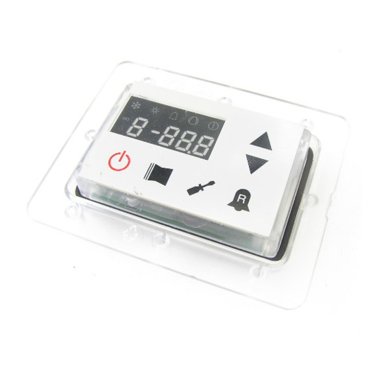
    Affichages de l’interface utilisateur et des paramètres L’interface utilisateur principal est représentée par un panneau à DEL avec clavier capacitif (c'est-à-dire avec des touches à effl eure- ment) ; les affi chages sont organisés à l'aide de trois menus : •...
  • Page 87: Menu Des Lectures

    Menu des lectures Pour entrer dans le menu des lectures, il faut appuyer sur la touche dans la (Fig. 5), la valeur de l'index, en la comparant avec le appuyer sur la touche dans la (Fig. 4). Une tandis que pour revenir à celle précédent, tableau reporté...
  • Page 88: Menu Lecture Avancée

    Menu LECTURE AVANCÉE Pour entrer dans le menu LECTURE de passe est 010; pour modifi er la va- la chaîne reste visualisée pendant une AVANCÉE appuyer sur la touche mon- leur du mot de passe utiliser les fl èches. seconde, après quoi elle est substituée trée dans la (Fig.7);...
  • Page 89: Menu Utilisateur

    Menu UTILISATEUR Pour entrer dans le menu UTILISATEUR, correct saisi, appuyer sur la touche indiquée de le sélectionner, appuyer sur la touche appuyer sur la touche indiquée dans la dans la (Fig. 7). L'index du paramètre UTI- indiquée dans la (Fig. 7), modifi er la valeur (Fig.
  • Page 90: Réglage Bande Proportionnelle À Froid

    Réglage bande proportionnelle à froid Valeur Valeur Index - chaîne Fonction du paramètre MIN. MAX. Ce paramètre indique la bande proportionnelle appliquée au point de consigne froid ; cette bande comporte une gestion optimisée du compresseur, en l'allumant uniquement si la 1 °C 20 °C température de l'eau d'entrée ou de sortie (sur la base du type de contrôle configuré...
  • Page 91: Réglage Du Point De Consigne De La Température À Froid 1

    Réglage du point de consigne de la température à froid 1 Valeur Valeur Index - chaîne Fonction du paramètre MIN. MAX. Ce paramètre indique la valeur maximale du point de consigne froid par rapport à la tempé- -20 °C 26 °C rature minimale de l'air extérieur (index (7) menu utilisateur).
  • Page 92: Programmation Du Réglage À Chaud 2

    Programmation du réglage à chaud 2 Valeur Valeur Index - Chaîne Fonction de paramètre Ce paramètre indique la valeur maximale du réglage à chaud, en correspondance à la température minimale de l'air externe (index (C) menu utilisateur). Ce paramètre est visible seulement si la fonction compensation (index (5) du menu utilisateur) est activée.
  • Page 93: Menu Installateur

    Menu INSTALLATEUR Pour entrer dans le menu INSTALLATEUR, diquée dans la (Fig. 9). L'index du paramètre quée dans la (Fig. 9), modifi er la valeur assi- appuyer sur la touche indiquée dans la INSTALLATEUR est visualisée sur l'affi cheur gnée indiquée dans la (Fig. 10) à l'aide des (Fig.
  • Page 94: Réglage Force-Off À Chaud

    Réglage FORCE-OFF à chaud Valeur Valeur Index - chaîne Fonction du paramètre MIN. MAX. Les pompes à chaleur prévoient un contrôle de la température de fonctionnement (entrée ou 30 °C 70 °C sortie), à laquelle est relié un seuil de sécurité, au-delà duquel le compresseur s'éteint immé- diatement et automatiquement.
  • Page 95: Réglage De La Résistance D'intégration Ou Activation De La Chaudière

    Réglage de la résistance d'intégration ou activation de la chaudière Valeur Valeur Index - chaîne Fonction du paramètre MIN. MAX. Ce paramètre indique la logique à utiliser lors de la gestion de la résistance électrique d'intégration. Cette logique est déterminée par la valeur réglée pour ce paramètre ; en fonction de la valeur, les réglages sont donc : 0 = aucune résistance d'intégration présente sur l'unité...
  • Page 96: Puissance Dédicacée À La Production D'eau Sanitaire

    • l'alarme de pompe (comme dans la version logicielle précédente) si le paramètre est réglé avec la valeur 3. De plus, se rappeler qu'en réglant ce paramètre avec la valeur 3, nous rendons compatible la carte Moducontrol avec la version logicielle précédente (3.6). Activation de la dérivation du fluxostat Valeur Valeur Index - chaîne...
  • Page 97: Veille De Température Ambiante Élevée

    Fonction du paramètre MIN. MAX. Ce paramètre indique la vitesse de communication entre le superviseur et le Moducontrol ; cette vitesse est réglée sur la base de la valeur sélectionnée pour ce paramètre : 0 = 9 600 bps 1 = 19 200 bps 2 = 38 400 bps Activation en écriture du superviseur...
  • Page 98: Limite Maximale Du Point De Consigne À Chaud Réglable

    Limite de température de l'air 1 Valeur Valeur Index - chaîne Fonction du paramètre MIN. MAX. Ce paramètre indique la température de l'air extérieur à laquelle l'appareil peut -25 °C 45°C produire sa valeur maximale d'eau (cette valeur est spécifiée par le paramètre P - St1).
  • Page 99: Menu Installateur 2

    Menu INSTALLATEUR 2 Pour entrer dans le menu INSTALLATEUR_2, suivre la même procédure décrite pour le menu INSTALLATEUR ; la seule modifi cation est la valeur du mot de passe qui est 31. ATTENTION : la modifi cation des paramètres suivants est du ressort exclusif du personnel qualifi...
  • Page 100: Menu Installateur 3

    Menu INSTALLATEUR 3 Pour entrer dans le menu INSTALLATEUR_3, suivre la même procédure décrite pour le menu INSTALLATEUR ; la seule modifi cation est la valeur du mot de passe qui est 84. ATTENTION : la modifi cation des paramètres suivants est du ressort exclusif du personnel qualifi...
  • Page 101: Gestion De La Résistance Électrique

    Gestion de la résistance électrique Les unités avec moducontrol prévoient Logique de sélection du mode de gestion de la résistance Fig.11 la possibilité de gérer une résistance électrique ; cette résistance peut être gérée selon différents modes : • Mode d'intégration (il prévoit une Résistance...
  • Page 102: Menu Résistance

    Menu RÉSISTANCE Pour entrer dans le menu RÉSISTANCE, rect saisi, appuyer sur la touche indi- (Fig. 15). Pour modifi er un paramètre, il appuyer sur la touche indiquée dans la quée dans la (Fig. 14). L'index du para- suffi t de le sélectionner, appuyer sur la (Fig.
  • Page 103: Réglage Du Point De Consigne De La Résistance D'intégration

    Réglage du point de consigne de la résistance d'intégration Valeur Valeur Index - chaîne Fonction du paramètre MIN. MAX. Ce paramètre indique le décalage du point de consigne chaud pour l'extinction de la résis- 0 °C 65 °C tance électrique (si active) dans le mode d'intégration , comme illustré dans la Fig. 12 à la page précédente (paramètre Sri).
  • Page 104: Tableau De Configuration Des Commutateurs Dip

    Ne pas oublier que certaines options pouvant être gérées à partir du pan- neau sont liées au réglage spécifi que de certains commutateurs DIP. Commutateur DIP (A) Réglages par défaut du COMMUTATEUR DIP MODUCONTROL COMMUTATEUR COMMUTATEUR DIP (A) DIP (B) Unités...
  • Page 105 Micro- N° Dip État Fonction interrupteur Appareil programmé comme pompe à chaleur Appareil programmé comme froid seul Dégivrage prévu seulement par inversion de cycle Dégivrage par injection de gaz chaud Eau/glycol : point de consigne antigel modifiable point de consigne antigel (Paramètre B) bloqué Contrôle rendement désactivé...
  • Page 106: Tableau Rècapitulatif Des Alarmes

    Tableau rècapitulatif des alarmes alarme. Les alarmes sont visualisées de cessive de la touche cloche permet de Les unités prévoient deux typologie dans la la même manière que les préalarmes signalisation du dysfonctionnement: visualiser la liste des alarmes (avec index sauf pour l'allumage du voyant rouge fixe.
  • Page 107 Code Code Cause Remarque Alarme Préalarme Cette signalisation se produit quand le transducteur en refou- Trasducteur pression refoulement lement résulte absent ert la machine est programmée comme compresseur absent pompe de chaleur ou la présence du DCP est programmée. Cette signalisation se produit quand le transducteur détecte une pression de refoulement supérieure au seuil de paramètre Haute pression set_fabbrica(8) (default: 40 bar).
  • Page 108 Code Code Cause Remarque Alarme Préalarme Module PFC Erreur del modulo inverter PFC (cod. longertek 23) Température excessive ailette de (cod. APY 1) refroidissement Surintensité en accélération Erreur matériel (cod. APY 2) Surintensité à vitesse constante Erreur matériel (cod. APY 3) Surintensité...
  • Page 109 Code Code Cause Remarque Alarme Préalarme Comunication entre onduleur et Onduleur Carel uPC absent Panne capteur température entraîne- Onduleur Carel ment Autoconfiguration manquée Onduleur Carel Entraînement onduleur désactivé Onduleur Carel Erreur phase moteur Onduleur Carel Vanne de refroidissement Onduleur Carel Onduleur en panne Vitesse défaut Onduleur Carel...
  • Page 111: Eg-Konformitätserklärung

    AERMEC S.p.A. I-37040 Bevilacqua (VR) Italien – Via Roma 996 Tel. (+39) 0442 633111 Telefax 0442 93730 – (+39) 0442 93566 www.aermec.com - info@aermec.com MODUCONTROL SERIENNUMMER EG-KONFORMITÄTS- Wir zeichnen eigenverantwortlich, dass die oben genannte Maschineneinheit, ERKLÄRUNG bestehend aus: NAME MODUCONTROL Elektronikplatine für LUFT/WASSER Kühlvorrichtung, Wärmepumpe...
  • Page 112 Eigenschaften der Regelvorrichtung ................115 Standardeinstellungen BENUTZEREBENE ..............116 Standardeinstellungen ELEKTROHEIZUNGSEBENE ..........117 Standardeinstellungen SERVICE-EBENE ..............118 Standardeinstellungen SERVICE-Ebene 2 ..............120 Geräte-Konfiguration mit MODUCONTROL ..............121 Anzeigen der Benutzerschnittstelle und Parameter ........... 122 Lese-Menü ........................123 Erweitertes INFO-Menü ....................124 ANWENDER-Menü ......................125 Einstellung der Betriebsparameter (Benutzerebene) .........
  • Page 113 Einstellung des Integrationswiderstands oder Aktivierung des Heizkessels ..131 Konfiguration der Paneelsteuerung ................. 131 Aktivierung des Brauchwarmwassers ..............131 Spezifische Leistung für die Brauchwarmwasserbereitung ........132 Wartezeit am Ein-/Ausgang ..................132 Wartezeit am Ein-/Ausgang ..................132 Umleitungsaktivierung des Strömungswächters ............. 132 Umleitungszeit des Strömungswächters ..............
  • Page 114: Vorsichtsmaßnahmen Und Sicherheitsvorschriften

    Die Garantie des Geräts deckt jedenfalls nicht die Kosten für Kraftfahrdrehleitern, Gerüste oder andere Hebesysteme, die sich bei Garantiearbeiten als erforderlich er- weisen sollten. Die AERMEC S.p.A. übernimmt keine Haftung für Schäden aus dem unsachgemäßen Gebrauch des Gerätes und der teilweisen oder oberfl ächlichen Lektü- re der in diesem Handbuch enthaltenen Informationen.
  • Page 115: Eigenschaften Der Regelvorrichtung

    Zubehör PR3 Scheda interfaccia protocollo ModBus Zubehör Modu_485A ACHTUNG: Für den Fall, dass eine GLT-Anbindung gewünscht wird, befi ndet sich ein Handbuch auf unserer Homepage www.aermec.com, mit allen hierfür benötigten Spezifi kationen, zur Realisierung eines seriellen Überwachungssys- tems. IMDCFJ. 12.05 6343841_03...
  • Page 116: Standardeinstellungen Benutzerebene

    Standardeinstellungen BENUTZEREBENE Parameter der BENUTZER-Ebene - (Passwort 000) Auf Einheit vorhanden Parameter Kürzel Parameter Index ANLI SRPV1 Gerät ist für Warmwasserbereitung geeignet (Wärmepumpe oder nur Heizbetrieb) Gerät ist für Kaltwasserbereitung geeignet (umschaltbare Wärmepumpe oder nur Kühlbetrieb) Alle Einheiten (sowohl Wärmepumpe, nur Heizbetrieb oder nur Kühlbetrieb) Gerät ist für Brauchwassererzeugung geeignet Parameter BENUTZER-Ebene relevante Funktionen Kürzel...
  • Page 117: Standardeinstellungen Elektroheizungsebene

    Standardeinstellungen ELEKTROHEIZUNGSEBENE Parameter der ELEKTROHEIZUNGS-Ebene - (Password 001) Auf Einheit vorhanden Parameter Kürzel Parameter Index ANLI SRPV1 Gerät ist für Warmwasserbereitung geeignet (Wärmepumpe oder nur Heizbetrieb), in der eine Elektro- Zusatzheizung vorgesehen ist. Alle Einheiten (sowohl Wärmepumpe, nur Heizbetrieb oder nur Kühlbetrieb) Parameter ELEKTROHEIZUNGS-Ebene relevante Funktionen Kürzel Kürzel...
  • Page 118: Standardeinstellungen Service-Ebene

    Standardeinstellungen SERVICE-EBENE Parameter der SERVICE-Ebene - (Password 030) Auf Einheit vorhanden Parameter Kürzel Parameter Index ANLI SRPV1 Gerät ist für Warmwasserbereitung geeignet (Wärmepumpe oder nur Heizbetrieb) Gerät ist für Kaltwasserbereitung geeignet (umschaltbare Wärmepumpe oder nur Kühlbetrieb) Alle Einheiten (sowohl Wärmepumpe, nur Heizbetrieb oder nur Kühlbetrieb) Gerät ist für Brauchwassererzeugung geeignet Parameter SERVICE-Ebene relevante Funktionen Kürzel...
  • Page 119 Parameter der SERVICE-Ebene - (Password 030) Auf Einheit vorhanden Parameter Kürzel Parameter Index ANLI SRPV1 Gerät ist für Warmwasserbereitung geeignet (Wärmepumpe oder nur Heizbetrieb) Alle Einheiten (sowohl Wärmepumpe, nur Heizbetrieb oder nur Kühlbetrieb) Gerät ist für Brauchwassererzeugung geeignet Parameter SERVICE-Ebene relevante Funktionen Kürzel Indice Bedeutung...
  • Page 120 Standardeinstellungen SERVICE-Ebene 2 Parameter der SERVICE-Ebene 2 - (Password 031) Auf Einheit vorhanden Parameter Index ANLI SRPV1 Gerät ist für Warmwasserbereitung geeignet (Wärmepumpe oder nur Heizbetrieb) Alle Einheiten (sowohl Wärmepumpe, nur Heizbetrieb oder nur Kühlbetrieb) Parameter SERVICE-Ebene 2 relevante Funktionen Kürzel Bedeutung Index...
  • Page 121: Geräte-Konfiguration Mit Moducontrol

    Geräte-Konfiguration mit MODUCONTROL Konfigurationsmöglichkeiten für jede Einheit Nur die Größen: ✔ ✘ ✘ ✘ ✔ 100, 150, 200 Nur die Größen: ✔ ✔ ✔ ✘ ✔ ANL H 100, 150, 200 ✔ ✔ ✔ ✘ ✔ ✔ ANLI ✔ ✔...
  • Page 122: Anzeigen Der Benutzerschnittstelle Und Parameter

    Anzeigen der Benutzerschnittstelle und Parameter Die Haupt-Benutzerschnittstelle besteht aus einer Led-Tafel mit kapazitiver Tastatur (d.h. mit auf Berührung reagierenden Schaltfl ächen). die Anzeigen sind in 3 Menüs organisiert: • LESE-Menü (Taste (C) Abb.1) Enthält die Informationen (nur im Lesemodus) zum laufenden Betrieb des Geräts.
  • Page 123: Lese-Menü

    Lese-Menü Für den Zugriff auf das Lese-Menü die den Wert der entsprechenden Ablesung wird in der ersten Sekunde neben der in Abbildung 4 gezeigte Taste drücken; ersetzt. Will man zur nächsten Ablesung Änderung des Indexwerts der String Im Lese-Menü erscheint am Display der übergehen, die in Abb.
  • Page 124: Erweitertes Info-Menü

    Erweitertes INFO-Menü Um das erweiterte INFO-Menü auf zu lautet 010; das Passwort kann mit den das Kürzel bleibt für ca. eine Sekunde rufen, die in (Abb.7) gezeigte Taste drü- Pfeil-Tasten geändert werden. Die kor- sichtbar und wird danach durch den cken;...
  • Page 125: Anwender-Menü

    ANWENDER-Menü Für den Zugriff auf das ANWENDER-Menü Eingabe des richtigen Passworts die in Abb. gang zum nächsten Parameter die Pfeiltas- die in Abb. 7 gezeigte Taste drücken; 7 gezeigte Taste drücken. Am Display wird ten benützen (Abb. 8). Für die Änderung anschließend das Passwort für den Zu- der Index des Parameters ANWENDER und eines Parameters muss man den Parameter...
  • Page 126: Einstellung Des Proportionalbereichs Im Kühlbetrieb

    Einstellung des Proportionalbereichs im Kühlbetrieb Wert Wert Index - String Parameterfunktion Min. Max. Dieser Parameter gibt die proportionale Bandbreite für den Sollwert im Kühlbetrieb an; in die- ser Bandbreite zeigt der Verdichter ein optimales Verhalten, er schaltet sich nur ein, wenn die 1°...
  • Page 127: Einstellung Des Temperatur-Sollwerts Im Kühlbetrieb 1

    Einstellung des Temperatur-Sollwerts im Kühlbetrieb 1 Wert Wert Index - String Parameterfunktion Min. Max. Dieser Parameter gibt den maximalen Sollwert im Kühlbetrieb in Zusammenhang mit der niedrigsten -20° C 26° C Außenlufttemperatur (Index (7) des Anwender-Menüs) an. Dieser Parameter wird nur angezeigt, wenn die Ausgleichsfunktion (Index (5) des Anwender-Menüs) aktiviert wurde.
  • Page 128: Einstellung Sollwert 2 Im Heizbetrieb

    Einstellung Sollwert 2 im Heizbetrieb Wert Wert Index - Kürzel Parameterbeschreibung Dieser Parameter zeigt den Mindest-Sollwert im Heizbetrieb, in Abhängigkeit der höchsten Außentemperatur (Index (C) Benutzer-Ebene) an. Dieser Parameter ist nur dann sichtbar, wenn die Kompensation (Index (5) Benutzer-Ebene) aktiviert wurde. (*): 25 °C - die Maximalbegrenzung wird mittels dem Parameter (t) in der Service-Ebene...
  • Page 129: Installateur-Menü

    INSTALLATEUR-Menü Für den Zugriff auf das INSTALLATEUR- Abb. 9 gezeigte Taste drücken. Am Display ter die Pfeiltasten benützen (Abb. 10). Für Menü die in Abb. 9 gezeigte Taste drücken; wird der Index des Parameters INSTALLA- die Änderung eines Parameters muss man anschließend das Passwort für den Zugriff TEUR und ein 3-Zeichen umfassender den den Parameter auswählen, die in Abb.
  • Page 130: Einstellung Von Force-Off Im Heizbetrieb

    Einstellung von FORCE-OFF im Heizbetrieb Wert Wert Index - String Parameterfunktion Min. Max. Die Wärmepumpen sehen eine Steuerung der Betriebstemperatur (Eingang oder Ausgang) vor, an die eine 30°C 70° C Sicherheitsschwelle gekoppelt wird, bei deren Überschreiten der Verdichter sofort und automatisch ausge- schaltet wird.
  • Page 131: Einstellung Des Integrationswiderstands Oder Aktivierung Des Heizkessels

    Einstellung des Integrationswiderstands oder Aktivierung des Heizkessels Wert Wert Index - String Parameterfunktion Min. Max. Dieser Parameter gibt die Logik an, die bei der Steuerung des elektrischen Integrationswiderstands zur Anwendung kommen muss; diese Logik wird vom Wert bestimmt, der in diesem Parameter eingestellt ist, die Einstellungen aufgrund des eingestellten Wertes lauten also: 0 = Im Gerät ist kein Integrationswiderstand vorhanden;...
  • Page 132: Spezifische Leistung Für Die Brauchwarmwasserbereitung

    • die Funktion Sperre von Verdichtern, Pumpe und Widerständen, wenn der Parameter auf 2 eingestellt • Pumpenalarm (wie in der vorherigen SW-Version), wenn der Parameter auf 3 eingestellt ist Es wird auch darauf hingewiesen, dass der Parameterwert 3 bedeutet, dass die Platine Moducontrol mit der früheren SW-Version (3.6) kompatibel gemacht wird Umleitungsaktivierung des Strömungswächters...
  • Page 133: Standby-Modus Bei Hoher Raumtemperatur

    Index - String Parameterfunktion Min. Max. Dieser Parameter gibt die Kommunikationsgeschwindigkeit zwischen Überwachungsvorrichtung und Moducontrol an; diese Geschwindigkeit wird aufgrund des für diesen Parameter ausgewählten Wertes eingestellt: 0 = 9600 bps 1 = 19200 bps 2 = 38400 bps Aktivierung des Schreibvorgangs bei der Überwachungsvorrichtung...
  • Page 134: Einstellbarer Maximaler Sollwert Für Heizbetrieb

    Außentemperaturgrenze 1 Wert Wert Index - String Parameterfunktion Min. Max. Dieser Parameter gibt die Außentemperatur an, bei der die Maschine ihren höchsten Wasserwert auf- -25° C 45°C bereiten kann (dieser Wert wird im Parameter P - St1 spezifiziert). Wassertemperaturgrenze 1 Wert Wert Index - String...
  • Page 135: Installateur 2-Menü

    INSTALLATEUR 2-Menü Für den Zugriff auf das Menü INSTALLATEUR_2 dieselbe Vorgangsweise anwenden, wie für das INSTALLATEUR-Menü beschrieben; die einzige Änderung ist der Wert des Passworts, dieser Wert ist 31. ACHTUNG: die Änderung der folgen- den Parameter ist ausschließlich dem Fachpersonal vorbehalten, das zur In- stallation des Geräts befugt ist.
  • Page 136: Installateur 3-Menü

    INSTALLATEUR 3-Menü Für den Zugriff auf das Menü INSTALLATEUR_3 dieselbe Vorgangsweise anwenden, wie für das INSTALLATEUR-Menü beschrieben; die einzige Änderung ist der Wert des Passworts, dieser Wert ist 84. ACHTUNG: die Änderung der folgen- den Parameter ist ausschließlich dem Fachpersonal vorbehalten, das zur In- stallation des Geräts befugt ist.
  • Page 137: Steuerung Des Elektrischen Widerstands

    Steuerung des elektrischen Widerstands Bei den Geräten mit Moducontrol ist Logik für die Auswahl der Steuerungsart es Widerstands Abb. 11 die Möglichkeit der Steuerung eines elektrischen Widerstands vorgese- hen; dieser Widerstand kann auf fol- Widerstand Widerstand Widerstand gende Arten gesteuert werden:...
  • Page 138: Menü Für Die Einstellung Der Widerstände

    Menü für die Einstellung der WIDERSTÄNDE Für den Zugriff auf das Menü für die Ein- be des richtigen Passworts die in Abb. zum nächsten Parameter die Pfeiltasten stellung der WIDERSTÄNDE die in Abb. 14 gezeigte Taste drücken. Am Display benützen (Abb. 15). Für die Änderung 14 gezeigte Taste drücken;...
  • Page 139: Einstellung Des Sollwerts Für Den Widerstand Mit Ergänzender Funktion

    Einstellung des Sollwerts für den Widerstand mit ergänzender Funktion Wert Wert Index - String Parameterfunktion Min. Max. Dieser Parameter gibt die Abweichung vom eingestellten Sollwert im Heizbetrieb an, für das 0° C 65° C Ausschalten des elektrischen Widerstands (falls aktiviert) bei der Steuerung mit ergänzender Funktion; wie in Abb.
  • Page 140: Tabelle Zur Konfiguration Der Dip-Schalter

    Funktionen der Maschine gesteuert werden können. Es wird darauf hingewiesen, dass eini- ge der über die Bedientafel steuerbaren Optionen an eine bestimmte Einstellung einiger Dip-Schalter gebunden sind. Dip-switch (A) Standard-Einstellungen DIP-SWITCH MODUCONTROL DIP-SWITCH DIP-SWITCH (A) Einer ANL H ANL C ANL A/Q...
  • Page 141 Dip-Schalter Dip-Nr. Zustand Funktion Maschine als Wärmepumpe eingerichtet Maschine als nur Kühlbetrieb eingerichtet Abtauen nur bei Zyklusumkehrung vorgesehen Abtauen durch Einspritzung heißen Gases Wasser-Glykol-Mischung Frostschutz-Sollwert änderbar Frostschutz-Sollwert (Parameter B) gesperrt Steuerung deaktiviert Steuerung aktiviert Sicherheits-Leistungsregelungen deaktiviert Sicherheits-Leistungsregelungen aktiviert Steuer-Algorithmus für niedrigen Wassergehalt deaktiviert Steuer-Algorithmus für niedrigen Wassergehalt aktiviert Vorrichtung zur Steuerung des Kondensationsdrucks vorhanden (DCP-Zubehör) Vorrichtung zur Steuerung des Kondensationsdrucks nicht vorhanden (DCP-Zubehör)
  • Page 142: Alarm Übersichtstabelle

    Alarm Übersichtstabelle die Voralarme angezeigt, mit Ausnahme ermöglicht es eine Alarm-Liste aufzurufen Die Geräte verfügen über zwei Arten der der nicht blinkenden, sondern rot leuchten- Übermittlung von Fehlfunktionen: (mit Index und Auslöser siehe nachfolgen- den Anzeige im Display. Bevor die Störung de Tabelle).
  • Page 143 Alarm Voralarm Ursache Bemerkung Code Code Diese Meldung erscheint, wenn der Hochdrucktransmitter nicht Hochdrucktransmitter abwesend angeklemmt oder defekt, und das Gerät als WP oder/und mit Drehzahlregelung konfiguriert ist. Diese Meldung erscheint, wenn der vom Hochdrucktransmitter gemessene Wert, den eingestellten Wert Hersteller-Ebene(8) (Standard: 40 bar) überschreitet.
  • Page 144 Alarm Voralarm Ursache Bemerkung Code Code Übertemperatur an Kühllamellen (cod. APY 1) Überstrom bei Beschleunigung Hardware-Fehler (cod. APY 2) Überstrom bei konstanter Drehzahl Hardware-Fehler (cod. APY 3) Überstrom bei Hardware-Fehler (cod. APY 4) Drehzahlreduzierung Unterspannung am DC-Bus (cod. APY 5) Überspannung am DC-Bus (cod.
  • Page 145 Alarm Voralarm Ursache Bemerkung Code Code Kommunikation zwischen Inverter Inverter Carel und uPC abwesend Drive Temperaturfühler defekt Inverter Carel Autokonfiguration fehlerhaft Inverter Carel Inverter-Drive deaktiviert Inverter Carel Motor-Phasen Fehler Inverter Carel Inverter Kühlventilator defekt Inverter Carel Drehzahl-Fehler Inverter Carel Dieser Alarm erscheint bei aktivem PFC, während der PFC Fehler DC-Bus sehr niedrig ist.
  • Page 147: Número De Serie

    AERMEC S.p.A. I-37040 Bevilacqua (VR) Italia – Via Roma, 996 Tel. (+39) 0442 633111 Telefax 0442 93730 – (+39) 0442 93566 www.aermec.com - info@aermec.com MODUCONTROL NÚMERO DE SERIE DECLARACIÓN Los que suscriben la presente declaran bajo la propia y exclusiva responsabilidad que el conjunto...
  • Page 148 Ajustes por defecto del MENÚ DE INSTALADOR ............154 Ajustes por defecto del MENÚ DE INSTALADOR 2 ............. 156 Configuración de la unidad con MODUCONTROL ............157 Visualizaciones de la interfaz usuario y de los parámetros ........158 Menú lecturas ........................ 159 Menú...
  • Page 149 Configuración frost protection ................. 166 Configuración de la resistencia integración o activación caldera ......167 Configuración control del panel ................167 Habilitación del agua sanitaria ................167 Potencia destinada a la producción de agua sanitaria ........... 168 Tiempo de espera en Entrada/salida ..............168 Tiempo de espera en Entrada/salida ..............
  • Page 150: Precauciones Y Normas De Seguridad

    En cualquier caso, la garantía del aparato no cubre los costes debidos a escaleras automáticas, andamios u otros sistemas de elevación que fuesen necesarios para efectuar las intervenciones en garantía. AERMEC S.p.A. declina toda responsabilidad por cualquier daño debido a un uso impropio de la máquina, o bien a una lectura par- cial o superfi...
  • Page 151: Características De La Regulación

    Accesorio Modu_485A ATENCIÓN: en el caso de que deseara implementar un sistema de gestión BMS, está disponible en nuestra página web www.aermec.com un manual con todas las especicifi caciones necesarias para la realización de un sistema de super- visión serial.
  • Page 152 Ajustes por defecto del MENÚ DE USUARIO Parámetros del Menú USUSARIO - (Password 000) Presente en las uni- dades Línea parámetro Indice parámetro ANLI SRPV1 Unidad capaz de producir agua caliente (bomba de calor o unidad sólo calor) Unidad capaz de producir agua caliente (bomba de calor o unidad sólo calor) Todas las unidades (ya sea bomba de calor, sólo calor o sólo frío) Unidad preparada para producir agua caliente sanitaria Funciones relativas a los parámetros del Menú...
  • Page 153 Ajustes por defecto de la RESISTENCIA Parámetros del Menú RESISTENCIA - (Password 001) Presente en las unidades Línea parámetro Indice parámetro ANLI SRPV1 Unidad preparada para producir agua caliente (bomba de calor o unidad sólo calor), en la que está prevista una resistencia eléctrica complementaria Todas las unidades (ya sea bomba de calor, sólo calor o sólo frío) Funciones relativas a los parámetros del Menú...
  • Page 154 Ajustes por defecto del MENÚ DE INSTALADOR Parámetros del Menú de INSTALADOR - (Password 030) Presente en las uni- dades Línea parámetro Indice parámetro ANLI SRPV1 Unidad capaz de producir agua caliente (bomba de calor o unidad sólo calor) Unidad capaz de producir agua caliente (bomba de calor o unidad sólo calor) Todas las unidades (ya sea bomba de calor, sólo calor o sólo frío) Unidad preparada para producir agua caliente sanitaria Funciones relativas a los parámetros del Menú...
  • Page 155 Parámetros del Menú de INSTALADOR - (Password 030) Presente en las uni- dades Línea parámetro Indice parámetro ANLI SRPV1 Unidad capaz de producir agua caliente (bomba de calor o unidad sólo calor) Todas las unidades (ya sea bomba de calor, sólo calor o sólo frío) Unidad preparada para producir agua caliente sanitaria Funciones relativas a los parámetros del Menú...
  • Page 156 Ajustes por defecto del MENÚ DE INSTALADOR 2 Parámetros del Menú de INSTALADOR 2 - (Password 031) Presente en las uni- dades Indice parámetro ANLI SRPV1 Unidad capaz de producir agua caliente (bomba de calor o unidad sólo calor) Todas las unidades (ya sea bomba de calor, sólo calor o sólo frío) Funciones relativas a los parámetros del Menú...
  • Page 157: Configuración De La Unidad Con Moducontrol

    Configuración de la unidad con MODUCONTROL Configuraciones disponibles para cada unidad Sólo tallas: ✔ ✘ ✘ ✘ ✔ 100, 150, 200 Sólo tallas: ✔ ✔ ✔ ✘ ✔ ANL H 100, 150, 200 ✔ ✔ ✔ ✘ ✔ ✔ ANLI ✔...
  • Page 158: Visualizaciones De La Interfaz Usuario Y De Los Parámetros

    Visualizaciones de la interfaz usuario y de los parámetros La interfaz usuario principal está representado por un panel de leds con teclado capacitivo (o sea, con botones táctiles); las visualizaciones se organizan mediante tres menús: • Menú LECTURAS (tecla (C) Fig.1) Contiene las informaciones (sólo en modalidad visualiza- ción) sobre el funcionamiento normal de la unidad.
  • Page 159: Menú Lecturas

    Menú lecturas Para ingresar al menú lecturas pulsar la pondiente a la lectura misma. Para pa- zará en el primer segundo la línea para tecla en (Fig.4); una vez ingresados al sar a la lectura siguiente es necesario identifi car la lectura en curso (sin em- menú...
  • Page 160: Menú Lecturas Avanzadas

    Menú LECTURAS AVANZADAS Para entrar en el menú LECTURAS seña es 010. Para modifi car el valor de caracteres que la identifi ca. La línea se AVANZADAS, presione la tecla que apa- las contraseñas use las teclas con las verá durante un segundo, después de rece en la fi...
  • Page 161: Menú Usuario

    Menú USUARIO Para ingresar al menú USUARIO pul- desplazamiento. Una vez ingresada la parámetro siguiente, usar las teclas de sar la tecla indicada en (Fig.7); una vez password correcta pulsar la tecla indica- desplazamiento (Fig.8). Para modifi car pulsada la tecla se deberá ingresar la da en (Fig.7).
  • Page 162: Configuración Banda Proporcional En Frío

    Configuración banda proporcional en frío Valor Valor Índice - línea Función del parámetro MÍN MÁX Este parámetro indica la banda proporcional aplicada al set frío; esta banda implica una gestión opti- mizada del compresor, encendiéndolo sólo si la temperatura del agua en entrada/salida (en base al 1°C 20°C tipo de control configurado por el parámetro (0) en el menú...
  • Page 163: Configuración Temperatura Aire Exterior 1 (En Caliente)

    Configuración del set temperatura en frío 1 Valor Valor Índice - línea Función del parámetro MÍN MÁX Este parámetro indica el valor máximo del set en frío, en correspondencia con la temperatura mínima -20°C 26°C del aire exterior (índice (7) menú usuario). Este parámetro es visible sólo si ha sido activada la función compensación (índice (5) menú...
  • Page 164: Configuración Temperatura Del Aire Exterior 2 (En Caliente)

    Configuración del set de calor 2 Valor Valor Índice - Línea Función del parámetro MÍN MÁX Este parámetro indica el máximo valor del set a calor, correspondiéndose con la temperatura mínima del aire exterior (índice b del menú de usuario). Este parámetro sólo es visible si se ha activado la función de compensación (índice 5 del menú...
  • Page 165: Menú Instalador

    Menú INSTALADOR Para ingresar al menú INSTALADOR ingresada la password correcta pulsar metro sucesivo, usar las teclas de des- pulsar la tecla indicada en (Fig.9); una la tecla indicada en (Fig.9). En la pan- plazamiento (Fig.10). Para modifi car un vez pulsada la tecla se deberá...
  • Page 166: Configuración Force-Off En Caliente

    Configuración FORCE-OFF en caliente Valor Valor Índice - línea Función del parámetro MÍN MÁX Las unidades de calor prevén un control de la temperatura de trabajo (entrada o salida) a la que se 30°C 70°C conecta un umbral de seguridad más allá del cual el compresor se apaga inmediata y automáticamen- te;...
  • Page 167: Configuración De La Resistencia Integración O Activación Caldera

    Configuración de la resistencia integración o activación caldera Valor Valor Índice - línea Función del parámetro MÍN MÁX Este parámetro indica la lógica que debe usarse en la gestión de la resistencia eléctrica de integra- ción. Esta lógica está determinada por el valor configurado en este parámetro. Por ello, en base al valor, las configuraciones son: 0 = Ninguna resistencia de integración presente en la unidad;...
  • Page 168: Potencia Destinada A La Producción De Agua Sanitaria

    • representa la alarma bomba (como en la versión software anterior), si el parámetro está configurado con el valor 3 Se recuerda además que si configuramos este parámetro con el valor 3, compatibilizamos la tarjeta moducontrol con la versión software anterior (3.6). Habilitación by-pass flujostato Valor Valor Índice - línea...
  • Page 169: Standby Por Elevada Temperatura Ambiente

    Índice - línea Función del parámetro MÍN MÁX Este parámetro indica la velocidad de comunicación entre supervisor y moducontrol; esta velocidad se configura en base al valor seleccionado para este parámetro: 0 = 9600 bps 1 = 19200 bps 2 = 38400 bps Habilitación escritura supervisor...
  • Page 170 Límite temperatura del aire 1 Valor Valor Índice - línea Función del parámetro MÍN MÁX Este parámetro indica la temperatura del aire exterior con la cual la máquina puede producir su máxi- -25°C 45°C mo valor de agua (este valor se especifica en el parámetro P - St1). Límite temperatura del agua 1 Valor Valor...
  • Page 171: Menú Instalador 2

    Menú INSTALADOR 2 Para ingresar al menú INSTALACIÓN_2 seguir el mismo procedimiento operativo descrito para el menú INSTALACIÓN; la única modifi cación es el valor de la contraseña que debe ser igual a 31. ATENCIÓN: la modifi cación de los si- guientes parámetros es competencia exclusiva del personal califi...
  • Page 172: Menú Instalador_3

    Menú INSTALADOR Para ingresar al menú INSTALACIÓN_3 seguir el mismo procedimiento operativo descrito para el menú INSTALACIÓN; la única modifi cación es el valor de la contraseña que debe ser igual a 84. ATENCIÓN: la modifi cación de los si- guientes parámetros es competencia exclusiva del personal califi...
  • Page 173: Control De La Resistencia Eléctrica

    Control de la resistencia eléctrica Las unidades con moducontrol pre- Lógica de selección de la modalidad de control de fi g. 11 vén la posibilidad de controlar una resistencia eléctrica. Esta resistencia la resistencia puede controlarse de acuerdo a dife-...
  • Page 174: Menú Resistencia

    Menú RESISTENCIA Para ingresar al menú RESISTENCIA password correcta pulsar la tecla indi- las teclas de desplazamiento (Fig.15). pulsar la tecla indicada en (Fig.14); una cada en (Fig.14). En la pantalla se visua- Para modifi car un parámetro basta se- vez pulsada la tecla se deberá...
  • Page 175: Configuración Del Set De La Resistencia Complementaria

    Configuración del set de la resistencia complementaria Valor Valor Índice - línea Función del parámetro MÍN MÁX Este parámetro indica la alteración del set point calor porque se apaga la resistencia eléctrica (si 0°C 65°C estuviera activa) en la modalidad integración, tal como se ilustra en la fig. 12 de la página anterior (Parámetro Sri).
  • Page 176: Tabella Configurazione Dip-Switch

    Si ricorda che alcune delle opzioni gestibili dal pannello sono vincolate ad uno specifi co settaggio di alcuni dip-switch. Dip-switch (A) Configuraciones por defecto DIP-SWITCH MODUCONTROL DIP-SWITCH (A) DIP-SWITCH (B) Unidades ANL H ANL C...
  • Page 177 Dip-switch N° Dip Estado Función Máquina configurada como bomba de calor Máquina configurada como sólo frío Desescarchado previsto sólo para inversión ciclo Desescarchado para inyección de gas caliente Agua glicolada: set antihielo modificable Set antihielo (Parámetro B) bloqueado Control rendimiento deshabilitado Control rendimiento habilitado Parcializaciones de seguridad deshabilitadas Parcializaciones de seguridad habilitadas...
  • Page 178: Tabla De Resumen De Alarmas

    Tabla de resumen de alarmas que las pre-alarmas, salvo que el piloto lizar la lista de las alarmas (cón índice y Las unidades prevén dos tipologías al rojo no parpadea. Antes de volver a activar señalar el mal funcionamiento: causa indicados en la tabla de abajo). Una la unidad, le aconsejamos contacte con el pre-alarma durará...
  • Page 179 Código Código Causas Notas Alarma Pre-alarma Esta señal se verifica cuando el transductor en envío del compre- Transductor de presión enviada sor está ausente y la máquina se configura como bomba de calor compresor ausente o se configura la presencia del DCP Esta señal se verifica cuando el transductor detecta una presión de envío superior al umbral del parámetro set_fabrica(8) (default: 40 bar).
  • Page 180 Código Código Causas Notas Alarma Pre-alarma Sobreintensidad en aceleración Error de hardware (cód. APY 2) Sobreintensidad a velocidad cons- Error de hardware (cód. APY 3) tante Sobreintensidad en deceleración Error de hardware (cód. APY 4) Subvoltaje en el DC Bus (cód.
  • Page 181 Código Código Causas Notas Alarma Pre-alarma Avería del sensor de temperatura Inverter Carel del drive Autoconfiguración fallida Inverter Carel Drive del inverter deshabilitado Inverter Carel Error fases del motor Inverter Carel Ventilador de enfriamiento Inverter Carel Inverter averiado Speed fault Inverter Carel Alarma que se verifica con PFC habilitado mientras que el PFC fault...
  • Page 184 AERMEC S.p.A. si riserva la facoltà di apportare in qualsiasi momento tutte le modifiche ritenute necessarie per il miglioramento del prodotto. Les données mentionnées dans ce manuel ne constituent aucun engagement de notre part. Aermec S.p.A. se réserve le droit de modifier à tous moments les données considérées nécessaires à...

Table des Matières