
Manuels Connexes pour Interroll MultiControl AI

Sommaire des Matières pour Interroll MultiControl AI
- Page 1 INSPIRED BY EFFICIENCY MultiControl AI / BI Analogue Interface / Bus Interface – 24 V / 48 V DC EN - Operating Manual FR - Notice d’utilisation...
-
Page 2: Manufacturer Details
All signs contained in this document (protected marks, such as logos and trade names) are the property of Interroll Holding AG, CH or of third parties and must not be used, copied or distributed without prior written consent. -
Page 3: Table Des Matières
Standard operation Special operation Applicable documentation Product information Product description Energy recovery/overvoltage protection Overload protection Setup MultiControl AI and BI Base plate Scope of delivery Rating plate Technical specifications Dimensions Version 2.7 (05/2021) UL Translation of the original operating manual... - Page 4 Contents Transport and storage Transport Storage Assembly and installation Warning notices for installation Assembling the MultiControl Initial assembly Subsequent assembly Warning notices for electrical installation Electrical installation Connecting the power supply Connecting the RollerDrive RollerDrive AI RollerDrive BI Connecting the bus Connecting the sensors Overview of connections Start-up and operation...
- Page 5 Contents Digital I/O States Digital I/O Settings Control Program Settings Error State Error Handling Settings MultiControl Error Log Teach-in Plug&Play CAN Gateway Service Change Password Service Restore Factory Settings Service MultiControl Restart Service Version Information Service – Up-/Download Magnetic sensor Service data objects (SDO) Operation Check before every start-up...
- Page 6 Contents Decommissioning and disposal Decommissioning Disposal Appendix 10.1 Accessories 10.2 Declarations of Conformity Version 2.7 (05/2021) UL 6 of 140 Translation of the original operating manual...
-
Page 7: About This Document
The operating manual is a component of the product and contains important advice and information regarding the different operating phases of the MultiControl. It describes the MultiControl at the time of shipping from Interroll. The currently applicable version of this operating manual can be found online at: www.interroll.com/products-solutions/downloads/... -
Page 8: Warning Notices In This Document
About this document Warning notices in this document Warning notices are provided in the context in which danger can occur and describe the nature of the danger in question. They are structured according to the following examples: SIGNAL WORD Type and source of hazard Consequence(s) in the event of non-compliance Measure(s) for avoiding hazard ¾... -
Page 9: Symbols
About this document NOTE Denotes a situation that can lead to material damage. Preventive measures ¾ Symbols This symbol indicates useful and important information. ü This symbol indicates a requirement that must be fulfilled before carrying out assembly or repair work. This symbol indicates general information relating to safety. -
Page 10: Safety-Related Information
The MultiControl may only be used in an industrial environment for industrial purposes within the stipulated performance limits that are given in the technical specifications. It controls up to four Interroll RollerDrives or VDC motors and must be integrated into a conveyor unit or conveyor system before commissioning. -
Page 11: Improper Use
Safety-related information Improper use Any use that goes beyond the proper use is considered improper, unless this has been authorised by Interroll Engineering GmbH where applicable. The equipment must not be installed in areas in which substances could form explosive atmospheres/dust atmospheres or for application in the medical/pharmaceutical sector. -
Page 12: Dangers
Safety-related information Dangers Here, you will find information about the different types of dangers or damage that can occur in connection with the operation of the MultiControl. Injury to persons ¾ Maintenance, installation and repair work on the unit must only be carried out by authorised technical personnel in compliance with the applicable provisions. -
Page 13: Interface To Other Devices
Information on the performance level according to DIN EN ISO 13849-1: 2015 The statistical analysis of the MultiControl AI / BI according to the „Part Counts Method” has led to the following result if the maximum permissible ambient temperature of 40 °C is observed:... -
Page 14: Operating Modes/Operating Phases
Applicable documentation The MultiControl AI/BI is part of the Interroll DC Platform, consisting of: • Interroll High Performance power supply unit HP5424 or HP 5448 (24 V DC/48 V DC) • Interroll MultiControl AI/BI • RollerDrive EC5000 AI/BI (24 V DC/48 V DC) •... -
Page 15: Product Information
Product information Product description The MultiControl is a control system for conveyor systems, which can control up to four Interroll RollerDrives. It is also a certified I/O device for PROFINET, EtherNet/IP and EtherCAT and can therefore be linked with other MultiControls and a PLC. -
Page 16: Setup
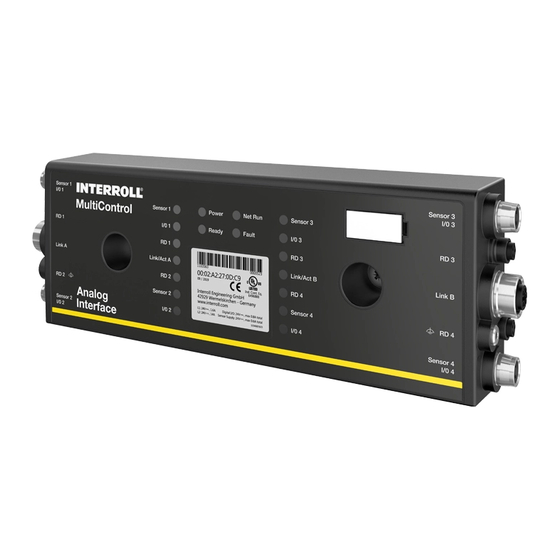
Product information Setup MultiControl AI and BI 1 Magnetic sensor 9 Motor RD 4 connection 2 LED for connections on the left 10 Sensor 4 / I/O 4 connection 3 Control status LED 11 Fastening screw 4 LED for connections on the right... -
Page 17: Base Plate
Product information Base plate 1 Cable guide for power supply to logic and sensors (L1) 2 Cable guide for power supply to RollerDrive (L2) 3 MultiControl fixing 4 Holes/slot for attaching the base plate Scope of delivery The scope of delivery of the MultiControl includes the following parts: •... -
Page 18: Rating Plate
Product information Rating plate The information on the rating plate allows the MultiControl to be identified. This is essential to be able to use the MultiControl as intended. 1 Article number 5 Serial number 2 MAC address 6 UL marking 3 Week/year of production 7 CE marking 4 Manufacturer... -
Page 19: Technical Specifications
Product information Technical specifications Rated voltage for logic and sensors (L1) 24 V DC, protected extra-low voltage (PELV) Voltage range L1 22 to 27,5 V DC Rated voltage for RollerDrive (L2) 24 V DC, protected extra-low 48 V DC, protected extra-low voltage (PELV) voltage (PELV) Voltage range L2... -
Page 20: Dimensions
Product information Dimensions The distance between the MultiControl and neighbouring components must be at least 10 mm in order to be able to operate the magnetic sensor. Version 2.7 (05/2021) UL 20 of 140 Translation of the original operating manual... -
Page 21: Transport And Storage
If any damage has been identified, photograph the damaged parts. ¾ In the event that damage has been incurred during transport, inform the shipping agent or Interroll ¾ immediately to ensure that you do not lose any potential damage claims. -
Page 22: Assembly And Installation
Assembly and installation Assembly and installation Warning notices for installation NOTE An improper approach to installing the MultiControl can lead to material damage or reduce the service life of the MultiControl. To preserve the interior of the MultiControl, do not allow the MultiControl to fall or for it to be used in an ¾... - Page 23 Assembly and installation Drill two holes with a diameter of 6.5 mm through the markings in the conveyor frame. ¾ Attach the base plate to the conveyor frame with M6 screws. ¾ Make sure the base plate has not been distorted. ¾...
-
Page 24: Subsequent Assembly
Assembly and installation Subsequent assembly If a MultiControl that has already been connected needs to be detached from the base plate, the ribbon cables must not make contact again at the same point, as otherwise proper contact cannot be guaranteed. So as not to have to disconnect the ribbon cables from all MultiControls and then reconnect them, in this case the MultiControl can be attached via the installation holes on the right. -
Page 25: Warning Notices For Electrical Installation
Assembly and installation Warning notices for electrical installation CAUTION Risk of injury when working on electrical equipment. Electrical installation work must only be carried out by a qualified electrician. ¾ Before installing, removing or connecting the MultiControl, switch off the power to the conveyor system and ¾... -
Page 26: Electrical Installation
Assembly and installation Electrical installation Connecting the power supply Two type 3G3G-FL ribbon cables with a wire cross-section of 2 x 2.5 mm are used for the power supplies. By using two ribbon cables, the RollerDrives and the sensors/logic have a separate voltage supply. This enables the RollerDrives to be safely shut down without interrupting bus communication. -
Page 27: Connecting The Rollerdrive
Assembly and installation Connecting the RollerDrive RollerDrive AI +24 V/48 V Input: Error Output: Rotational direction Output: Speed Earth Seal unused RollerDrive connections with an M8 blind cap to achieve protection rate IP54. ¾ RollerDrive BI +24 V/48 V CAN bus signal CAN Low CAN bus signal CAN High Service manufacturer Earth... -
Page 28: Connecting The Bus
Assembly and installation Connecting the bus Connections “Link A” and “Link B” are suitable for M12 connectors, four-pin, D-coded, contact assignment as per IEC 61076-2-101. Transmission Data TD+ Transmission Data TD- Receive Data RD+ Receive Data RD- The MultiControl features an integrated two-port switch. This enables the MultiControl to be integrated into line structures of the bus wiring, for example. -
Page 29: Connecting The Sensors
Assembly and installation Connecting the sensors Four sensors and four additional inputs or outputs (AUX I/O) can be connected at connections “Sensor 1, I/O 1” to “Sensor 4, I/O 4”. PNP or NPN sensors as well as sensors with N/C or N/O contact can be used. The sensor type and the function of the additional I/Os can be parametrised (see „Digital I/O - Settings“... -
Page 30: Overview Of Connections
Assembly and installation Characteristic values for the outputs Output voltage 24 V DC Maximum output current ≤ 200 mA Output voltage "1" for PNP > 15 V at 200 mA Output voltage "1" for NPN ≤ 5 V at 200 mA Seal any unused sensor connections with an M8 blind cap to achieve protection rate IP54. -
Page 31: Start-Up And Operation
Start-up and operation Start-up and operation Start-up Check before the initial start-up Ensure that the base plate of the MultiControl has been correctly attached to the profile, that the MultiControl ¾ has been correctly attached to the base plate and that all screws have been properly tightened. Ensure that no additional hazards are formed through the interfaces to other components. -
Page 32: Multicontrol User Interface
In the address line, enter the IP address of the MultiControl (default setting: http://192.168.0.1/). ¾ On the login page, enter the login data (default setting: User name “Interroll”, password “Interroll”). ¾ Unless otherwise specified, the figures apply to the MultiControl AI and the MultiControl BI. - Page 33 Start-up and operation MultiControl AI MultiControl Overview Bus Info Bus Protocol : PROFINET Overview Host Name : multicontrol2 Network and Settings IP Adress : 192.168.0.2 Motor State : Disconnected Settings TestPanel Error Info Digital I/O State : Operational States Active Error : BusComFail (21)
-
Page 34: Multicontrol Overview" Home
Start-up and operation “MultiControl Overview” home page MultiControl Overview Bus Info Bus Protocol : PROFINET Host Name : multicontrol2 IP Adress : 192.168.0.2 State : Disconnected Error Info State : Operational Active Error : BusComFail (21) Last Error : 00:00:42.536.21 BusComFail Control Program Info Program ID : I/O Device Version... -
Page 35: Network Settings
Start-up and operation Network Settings Network Settings Bus Protocol Neighbours EtherCAT IP address upstream : 192.168.0.16 EtherCAT/CAN IP address downstream : 192.168.0.17 PROFINET EtherNet/IP Option Addresses Big Endian Format IP address : 192.168.0.1 Process Image In/Out: Universal Full / Universal Full Network Mask : 255.255.255.0 Gateway : 0.0.0.0... -
Page 36: Motor Settings
Start-up and operation • IP addresses of neighbouring MultiControls (with ZPA and ZPA+ programs) IP address upstream: Address of the MultiControl from which articles, trays, materials to be conveyed, products, etc. are transferred IP address downstream: Address of the MultiControl to which articles, trays, materials to be conveyed, products, etc. - Page 37 Start-up and operation Deactivate unused motors to avoid error messages. ¾ Select the connected motor – EC5000 / EC310 / VDC Speed / VDC Position ¾ If a motor is activated but not connected, the RD1 – RD4 LED flashes. Enter the “Roller diameter”, “Gearing ratio”...
-
Page 38: Motor Information - Multicontrol Bi Only
Start-up and operation Motor Information – MultiControl BI only Motor Information Motor 1 Motor 2 Motor 3 Motor 4 Gear Ratio 49:1 49:1 Max. Speed [m/s] 0.37 0.37 N.C. Status Stop Stop N.C. Motor Name EC5000 EC5000 Hardware Vers. 1.0000 1.0000 Software Vers. -
Page 39: Motor Monitor - Multicontrol Bi Only
Start-up and operation Motor Monitor – MultiControl BI only Motor Monitor Motor 1 Motor 2 Motor 3 Motor 4 Lifetime Temperature Power Error Start/Stops 31536065 Run Time (hh:mm:ss) 0:19:42 3140:26:15 Up Time (hh:mm:ss) 288:45:16 8984:58:28 Temp. Max (°) ---- Temp. Min (°) Current Temp. -
Page 40: Motor Test For Ec5000
Start-up and operation Motor Test for EC5000 WARNING Risk of crushing due to unintentional start-up of the RollerDrive! Changes in this menu have direct influence on the connected RollerDrive! ¾ Before starting motors make sure, ensure that no persons are present in the hazardous areas surrounding ¾... -
Page 41: Digital I/O States
Start-up and operation Digital I/O States Digital I/O States Sensor 1 Sensor 3 State: Off Throughput: 0 Parts/Hour State: Off Throughput: 0 Parts/Hour I/O 1 I/O 3 State: Off State: Off Sensor 2 Sensor 4 State: Off Throughput: 0 Parts/Hour State: Off... -
Page 42: Digital I/O Settings
Start-up and operation Digital I/O Settings Digital I/O Settings Sensor 1 Sensor 3 Type Type Polarity positive negative Polarity positive negative ON Delay [ms] ON Delay [ms] OFF Delay [ms] OFF Delay [ms] I/O 1 I/O 3 Type Type Polarity positive negative Polarity... - Page 43 Start-up and operation Function Description Control output 3 Zone 3 occupied Control output 4 Zone 4 occupied Control output 5–8 No function Handshake in up Handshake signals to neighbouring ZPA modules Handshake in down Handshake in left Handshake in right Handshake out up Handshake out down Handshake out left...
-
Page 44: Control Program Settings
Start-up and operation Control Program Settings Control Program Settings Control Program Settings Program ID I/O Device Version : 2017-12-12-11 Control Timer Timer 1 [ms] Timer 2 [ms] Timer 3 [ms] Timer 4 [ms] Submit Reset Selection of control programs ZPA single release program ZPA train release program ZPA module program No ZPA program ID... -
Page 45: Error State
Start-up and operation Error State Error State Error Info State : Operational Active Error : BusComFail (21) Last Error : 00:02:29:756 51 DriveError #2 • Display of the current status of the MultiControl • Display of the current error • Display of the most recent error Error Handling Settings Error Handling Settings System Errors... - Page 46 Start-up and operation Under voltage error Supply voltage too low: Ignore: Error is not displayed. Warning: Error is indicated by fault LED flashing five times. The conveying process is not interrupted. Immediate stop: Error is indicated by fault LED flashing five times. The conveying process is interrupted.
-
Page 47: Multicontrol Error Log
Start-up and operation MultiControl Error Log MultiControl Error Log Error Info Time Error Description 00:00:06:823 SystemRestart 00:00:06:460 SystemRestart 00:00:06:459 SystemRestart 00:00:06:790 SystemRestart 00:00:06:799 SystemRestart 00:00:07:823 BusStartUp 00:00:11:131 NewStateTable 00:00:11:153 NewStateTable 00:00:11:154 DriveError #1 00:00:11:154 DriveError #2 00:00:11:154 DriveError #3 00:00:11:154 DriveError #4 00:00:11:161... -
Page 48: Teach-In
Start-up and operation Teach-in WARNING Risk of crushing due to unintentional start-up of the RollerDrive! Changes in this menu have direct influence on the connected RollerDrive! ¾ Before starting motors make sure, ensure that no persons are present in the hazardous areas surrounding ¾... -
Page 49: Service Change Password
Start-up and operation Service Change Password Service Change Password Change password Enter old password Enter new password : Repeat new password : Submit Reset To change the password, enter the old password followed by the new password twice and transfer this to the ¾... -
Page 50: Service Multicontrol Restart
Start-up and operation Service MultiControl Restart Service MultiControl Restart MultiControl restart CAUTION: A restart of MultiControl will stop the control process and interrupt the network connection. Do you want to restart MultiContol now? Submit Reset Restarting the MultiControl: Select “Yes” ¾... -
Page 51: Service - Up-/Download
Start-up and operation Service – Up-/Download Up- Download Download Upload For download under a different name, please use „Right Click --> Save To make settings effective, please restart module afterwards! As...“-option Bus Config upload Bus Config download Application Config upload Application Config download The MultiControl settings can be downloaded via the user interface and saved to a computer. -
Page 52: Magnetic Sensor
A magnet is required in order to operate the magnetic sensor (see „Accessories“ on page 66). The magnetic sensor is located on the top of the MultiControl, between the two Rs of “INTERROLL” directly in front of the base plate (see „Setup“... -
Page 53: Operation
Start-up and operation Operation WARNING Risk of crushing due to unintentional start-up of the RollerDrive! Before switching on the power supply, ensure that no persons are present in the hazardous areas ¾ surrounding the conveyor system! In ZPA mode, all connected RollerDrives carry out an initialization run for a maximum of four seconds after ¾... -
Page 54: Procedure In The Event Of Accidents Or Faults
Start-up and operation Procedure in the event of accidents or faults Stop the conveyor system immediately, switch off the power supply and ensure that it cannot be unintentionally ¾ switched on again. In the event of an accident: Perform first aid and call for the emergency services. ¾... -
Page 55: Maintenance And Cleaning
Maintenance and cleaning Maintenance and cleaning CAUTION Risk of injury from following incorrect procedure. Maintenance and repair work must only be carried out by authorised and trained (specialist) personnel. ¾ Maintenance and repair work must only be carried out when the system has been disconnected from the ¾... -
Page 56: Cleaning
Maintenance and cleaning Cleaning Under humid conditions, dust and dirt can cause a short circuit. Therefore, ensure dirty environments are cleaned regularly to prevent short circuits that could damage the MultiControl. NOTE The MultiControl can be damaged if it is not properly cleaned. Never immerse the MultiControl in fluids. -
Page 57: Assistance In The Event Of Faults
Assistance in the event of faults Assistance in the event of faults Understanding the LEDs LEDs on the MultiControl indicate the operating state of the conveyor. Status description of the LEDs: • Off: LED is permanently off • On: LED is permanently on •... - Page 58 Assistance in the event of faults Power Ready Net run Fault Meaning Priority Flashes x6 Voltage error, overvoltage Flashes x7 Temperature in the MultiControl too high. Flashes x8 Overload protection for the brake resistor active. Flashes x9 Handshake communication interrupted. See instructions on ZPA and ZPA+ applications.
-
Page 59: Connection Leds
More detailed error diagnosis is possible via the PLC. If you are not able to successfully troubleshoot the problem or eliminate the error, contact Interroll Support and have the following information to hand: •... - Page 60 Assistance in the event of faults Fault Possible cause Remedy Communication error Connection to PLC interrupted Check the bus wiring ¾ Check the bus type ¾ Check the network address ¾ and bus name RollerDrive error Error signal from the RollerDrive Check the motor ¾...
- Page 61 Assistance in the event of faults Fault Possible cause Remedy RollerDrive does not rotate RollerDrive not or not correctly Ensure that the power supply ¾ connected or RollerDrive defective is within the specified voltage range Check the connections and ¾ correct them if necessary Replace the RollerDrive if ¾...
-
Page 62: Error Codes
Assistance in the event of faults Error codes Short text Comments ApplErrorNone No error in the application program ApplErrUnk Unknown error in the application program ApplErrSystemSevere Severe system error ApplErrSystemMinor Minor system error ApplErrSystemWarning Warning PllErrItemNotFound Searched for object not found ApplErrRange Number outside the valid value range ApplErrNoTerminlInput... - Page 63 Assistance in the event of faults Short text Comments ApplErrErrorLogUpdate Access error to error log file ApplErrPanellllMode Change of mode not permitted ApplErrPanelLedBlocked Access to LED control not permitted ApplErrInvalidApplConf Invalid configuration of the application program ApplErrDriveError1 RollerDrive 1 error ApplErrDriveError2 RollerDrive 2 error ApplErrDriveError3...
- Page 64 Assistance in the event of faults Short text Comments ApplErrMotorVoltage Voltage error: No motor voltage ApplErrOvcOverloaded Brake resistor overload ApplErrRemoteEmergency Emergency stop from neighbouring transfer device ApplErrInvalidStateTblConf Error when loading the application program ApplErrNewStateTable New application program loaded ApplErrInvalidErrConf Invalid configuration for the selected application program ApplErrInvalidTeachParams Invalid parameters for teach-in procedure ApplErrPapSaveConfig...
-
Page 65: Decommissioning And Disposal
Decommissioning and disposal Decommissioning and disposal CAUTION Risk of injury from following incorrect procedure. Decommissioning must only be carried out by authorised, qualified personnel. ¾ Only decommission the MultiControl when the system has been disconnected from the power supply. ¾ Switch off the power to the MultiControl and ensure that it cannot be unintentionally switched on again. -
Page 66: Appendix
Appendix Appendix 10.1 Accessories Article Article number Ribbon cable distributor S-1115717 Ribbon cable for power supply (25 m) S-1004030 High Performance power supply unit HP 5424 S-1113899 High Performance power supply unit HP 5448 S-1113900 Magnetic key S-64100210 MultiControl Y-cable S-1104460 MultiControl communication cable (3 m) S-1104438... -
Page 67: Declarations Of Conformity
Höferhof 16 42929 Wermelskirchen Germany hereby declares that the • Interroll MultiControl AI – model number 1103563 • Interroll MultiControl BI – model number 1103564 conform to the applicable provisions and the associated CE marking in accordance with the aforementioned Directives. - Page 68 Appendix Version 2.7 (05/2021) UL 68 of 140 Translation of the original operating manual...
-
Page 69: Adresse Du Fabricant
Tous les signes contenus dans ce document (marques protégées, comme des logos et des désignations commerciales) sont la propriété de Interroll Holding AG, CH ou de tiers et ne doivent pas être utilisés, copiés ou distribués sans autorisation écrite et préalable. - Page 70 Documentation en vigueur Informations produit Description du produit Récupération de l’énergie / protection contre les surtensions Protection contre la surcharge Construction MultiControl AI et BI Plaque de base Volume de livraison Plaque signalétique Données techniques Dimensions Version 2.7 (05/2021) UL 70 sur 140 Traduction de la notice d’utilisation originale...
- Page 71 Sommaire Transport et stockage Transport Stockage Montage et installation Avertissements concernant le montage Montage de la MultiControl Montage initial Nouveau montage Avertissements concernant le montage électrique Installation électrique Raccordement de l’alimentation électrique Raccordement du RollerDrive RollerDrive AI RollerDrive BI Raccordement bus Raccordement des capteurs Vue d’ensemble des raccordements Mise en service et fonctionnement...
- Page 72 Sommaire Digital I/O States Digital I/O Settings Control Program Settings Error State Error Handling Settings MultiControl Error Log Teach-in Plug&Play CAN Gateway Service Change Password Service Restore Factory Settings Service MultiControl Restart Service Version Information Service - Up-/Download Capteur magnétique Service Data Objects (SDO) Fonctionnement Contrôle avant chaque mise en service...
- Page 73 Sommaire Démontage et élimination Démontage Élimination Annexe 10.1 Accessoires 10.2 Déclarations de conformité Version 2.7 (05/2021) UL Traduction de la notice d’utilisation originale 73 sur 140...
- Page 74 Version 2.7 (05/2021) UL 74 sur 140 Traduction de la notice d’utilisation originale...
-
Page 75: Propos Du Présent Document
La notice d’utilisation fait partie du produit et contient des remarques et informations importantes sur les différentes phases de fonctionnement de la MultiControl. Elle décrit la MultiControl au moment de sa livraison par Interroll. Vous trouverez la version actuelle de la présente notice d’utilisation sur Internet à l’adresse : www.interroll.com/products-solutions/downloads/... -
Page 76: Avertissements Dans Ce Document
À propos du présent document Avertissements dans ce document Les avertissements sont mentionnés dans le contexte dans lequel un danger peut survenir, sur lequel porte l’avertissement. Ils sont organisés selon le modèle suivant : MOT CLÉ Nature et source du danger Conséquence(s) en cas de non-respect Mesure(s) pour éviter le danger ¾... -
Page 77: Symboles
À propos du présent document REMARQUE Désigne une situation qui peut entraîner des dommages matériels. Mesures pour éviter ¾ Symboles Ce symbole indique des informations utiles et importantes. ü Ce signe désigne une condition qui doit être remplie avant les travaux de montage ou de maintenance. Ce symbole désigne des informations générales concernant la sécurité. -
Page 78: Informations Concernant La Sécurité
Informations concernant la sécurité État de la technique La MultiControl d’Interroll est montée en tenant compte des normes en vigueur et de l’état de la technique et elle est livrée pour un fonctionnement en toute sécurité. Toutefois, des risques peuvent apparaître pendant l’utilisation. -
Page 79: Utilisation Contraire Aux Dispositions
La présente notice d’utilisation s’adresse aux groupes cibles suivants : Opérateurs Les opérateurs sont formés au fonctionnement et au nettoyage de la MultiControl Interroll et respectent les directives de sécurité. Personnel de service Le personnel de service dispose d’une formation technique spécialisée ou a suivi une formation du fabricant et... -
Page 80: Dangers
Informations concernant la sécurité Dangers Vous trouverez ici des informations sur les différents types de dangers ou de dommages qui peuvent survenir dans le cadre de l'utilisation de la MultiControl. Dommages physiques ¾ Ne faire réaliser les travaux de maintenance, d’installation et de réparation sur l’appareil que par un personnel spécialisé... -
Page 81: Interface Avec D'autres Appareils
Informations sur le niveau de performance selon DIN EN ISO 13849-1: 2015 L’analyse statistique du MultiControl AI / BI selon la « Part Counts Method » a conduit au résultat suivant si la température ambiante maximale autorisée de 40° C est respectée:... -
Page 82: Modes De Fonctionnement / Phases
Élimination Documentation en vigueur La MultiControl AI / BI fait partie de la plate-forme DC Interroll, qui comprend les éléments suivants : • Bloc d’alimentation High Performance HP5424 ou HP 5448 (24 V DC / 48 V DC) Interroll • MultiControl AI / BI Interroll •... -
Page 83: Informations Produit
Elle peut ainsi être utilisée comme commande individuelle, avec ou sans API reliée. La MultiControl est compatible avec tous les modules de convoyage 24 V et 48 V d’Interroll Automation GmbH. Des programmes ZPA (Zero Pressure Accumulation) sont utilisés dans le cas du fonctionnement des modules de convoyage sans pression dynamique. -
Page 84: Construction
Informations produit Construction MultiControl AI et BI 1 Capteur magnétique 9 Raccordement moteur RD 4 2 LED pour les raccordements à gauche 10 Raccordement capteur 4 / I/O 4 3 Commande de l'état des LED 11 Vis de fixation 4 LED pour les raccordements à droite 12 Plaque signalétique... -
Page 85: Plaque De Base
Informations produit Plaque de base 1 Guidage du câble d'alimentation électrique logique et capteurs (L1) 2 Guidage du câble d'alimentation électrique RollerDrive (L2) 3 Fixation de la MultiControl 4 Trous ronds / oblongs pour la fixation de la plaque de base Volume de livraison Les pièces suivantes sont fournies à... -
Page 86: Plaque Signalétique
Informations produit Plaque signalétique Les informations sur la plaque signalétique permettent d’identifier la MultiControl. C’est indispensable pour pouvoir utiliser la MultiControl conformément aux dispositions. 1 Référence article 5 Numéro de série 2 Adresse MAC 6 Marquage UL 3 Semaine/année de production 7 Marquage CE 4 Fabricant 8 Données de connexion... -
Page 87: Données Techniques
Informations produit Données techniques Tension nominale logique et capteurs (L1) 24 V DC, basse tension de protection PELV Plage de tension L1 22 à 27,5 V DC Tension nominale RollerDrive (L2) 24 V DC, basse tension de 48 V DC, basse tension de protection PELV protection PELV Plage de tension L2... -
Page 88: Dimensions
Informations produit Dimensions L'écartement entre le bord supérieur de la MultiControl et les pièces voisines doit au moins s'élever à 10 mm afin de permettre l'utilisation du capteur magnétique. Version 2.7 (05/2021) UL 88 sur 140 Traduction de la notice d’utilisation originale... -
Page 89: Transport Et Stockage
¾ Photographier les pièces endommagées en cas de dommages constatés. ¾ En cas de dommages causés par le transport, informer immédiatement le transporteur et Interroll pour ne pas ¾ perdre d’éventuels droits à des dommages-intérêts. Ne pas exposer la MultiControl à de fortes variations de température, car cela peut entraîner la formation de ¾... -
Page 90: Montage Et Installation
Montage et installation Montage et installation Avertissements concernant le montage REMARQUE Une mauvaise manipulation lors du montage de la MultiControl peut entraîner des dommages matériels ou un raccourcissement de la durée de vie de la MultiControl. Ne pas faire tomber la MultiControl et ne pas l'utiliser de manière non conforme pour éviter des dommages ¾... - Page 91 Montage et installation Percer deux trous d’environ 6,5 mm de diamètre sur les marquages du châssis du convoyeur. ¾ Visser la plaque de base sur le convoyeur à l’aide de vis M6. ¾ S’assurer que la plaque de base n’a subi aucune torsion. ¾...
-
Page 92: Nouveau Montage
Montage et installation Nouveau montage Si une MultiControl déjà raccordée doit être desserrée de la plaque arrière, les câbles plats ne doivent pas être mis en contact au même endroit car la conformité du contact ne serait alors pas garantie. La MultiControl peut alors être fixée dans le trou de montage de droite afin que le câble plat n’ait pas besoin d’être desserré... -
Page 93: Avertissements Concernant Le Montage Électrique
Montage et installation Avertissements concernant le montage électrique ATTENTION Risque de blessure dans le cadre de travaux sur l'équipement électrique ! Ne faire réaliser des travaux sur l'installation électrique que par un électricien qualifié. ¾ Avant d'installer, retirer ou raccorder la MultiControl, mettre l'installation de convoyage hors tension et la ¾... -
Page 94: Installation Électrique
Montage et installation Installation électrique Raccordement de l’alimentation électrique Pour l’alimentation électrique, deux câbles plats de type 3G3G-FL présentant une section de conducteur de 2 x 2,5 mm sont utilisés. Utiliser deux câbles plats permet d’alimenter en tension le RollerDrive ainsi que les capteurs / la logique séparément. Le RollerDrive peut ainsi être déconnecté... -
Page 95: Raccordement Du Rollerdrive
Montage et installation Raccordement du RollerDrive RollerDrive AI +24 V / 48 V Entrée erreur Sortie sens de rotation Sortie vitesse Masse Obturer les raccordements du RollerDrive non utilisés avec un embout M8 afin d’atteindre la classe de ¾ protection IP54. RollerDrive BI +24 V / 48 V Signal de bus CAN - CAN Low Signal de bus CAN - CAN High... -
Page 96: Raccordement Bus
Montage et installation Raccordement bus Les deux raccordements « Link A » et « Link B » sont adaptés à un connecteur M12, 4 pôles, codage D, affectation des contacts selon CEI 61076-2-101 : Transmission Data TD+ Transmission Data TD- Receive Data RD+ Receive Data RD- La MultiControl est équipée d’un commutateur 2 ports intégré. Ainsi, la MultiControl peut par exemple être intégrée dans les structures linéaires du câblage de bus. -
Page 97: Raccordement Des Capteurs
Montage et installation Raccordement des capteurs Quatre capteurs (« Sensor ») et quatre entrées et sorties supplémentaires (Aux I/O) peuvent être branchés sur les raccordements « Sensor 1, I/O 1 » à « Sensor 4, I/O 4 » de la MultiControl. Il est possible d’utiliser des capteurs PNP ou NPN ainsi que des capteurs dotés de contacts à... -
Page 98: Vue D'ensemble Des Raccordements
Montage et installation Paramètres des sorties Tension de sortie 24 V DC Courant de sortie maximal ≤ 200 mA Tension de sortie « 1 » sur PNP > 15 V @ 200 mA Tension de sortie « 1 » sur NPN ≤ 5 V @ 200 mA Si un raccordement de capteur reste inutilisé, obturer ce dernier avec un embout M8 afin d’atteindre la classe ¾... -
Page 99: Mise En Service Et Fonctionnement
Mise en service et fonctionnement Mise en service et fonctionnement Mise en service Contrôle avant la première mise en service S’assurer que la plaque de base de la MultiControl a été correctement fixée sur le profil, que la MultiControl a ¾... -
Page 100: Interface Utilisateur Multicontrol
¾ Saisir les identifiants sur la page de connexion (par défaut : User Name « Interroll », Password « Interroll »). ¾ Sauf indication contraire, les illustrations décrites s'appliquent à la MultiControl AI et à la MultiControl BI. Version 2.7 (05/2021) UL 100 sur 140... - Page 101 Mise en service et fonctionnement MultiControl AI MultiControl Overview Bus Info Bus Protocol : PROFINET Overview Host Name : multicontrol2 Network and Settings IP Adress : 192.168.0.2 Motor State : Disconnected Settings TestPanel Error Info Digital I/O State : Operational...
-
Page 102: Page D'accueil « Multicontrol Overview
Mise en service et fonctionnement Page d’accueil « MultiControl Overview » MultiControl Overview Bus Info Bus Protocol : PROFINET Host Name : multicontrol2 IP Adress : 192.168.0.2 State : Disconnected Error Info State : Operational Active Error : BusComFail (21) Last Error : 00:00:42.536.21 BusComFail Control Program Info Program ID : I/O Device... -
Page 103: Network Settings
Mise en service et fonctionnement Network Settings Network Settings Bus Protocol Neighbours EtherCAT IP address upstream : 192.168.0.16 EtherCAT/CAN IP address downstream : 192.168.0.17 PROFINET EtherNet/IP Option Addresses Big Endian Format IP address : 192.168.0.1 Process Image In/Out: Universal Full / Universal Full Network Mask : 255.255.255.0 Gateway : 0.0.0.0... -
Page 104: Motor Settings
Mise en service et fonctionnement • Adresses IP des MultiControl voisines (pour les programmes ZPA et ZPA+) IP adress upstream : Adresse de la MultiControl à partir de laquelle les articles, conteneurs, produits transportés, produits,... sont repris IP adress downstream : Adresse de la MultiControl à partir de laquelle les articles, conteneurs, produits transportés, produits,... - Page 105 Mise en service et fonctionnement Désactiver les moteurs non utilisés afin d’éviter les connexions erronées. ¾ Sélectionner le moteur raccordé - EC5000 / EC310 / VDC Speed / VDC Position ¾ Si un moteur est activé mais qu'il n'est pas raccordé, la LED RD1 - RD4 clignote. Saisir les informations correspondant au RollerDrive utilisé...
-
Page 106: Motor Information - Multicontrol Bi Uniquement
Mise en service et fonctionnement Motor Information - MultiControl BI uniquement Motor Information Motor 1 Motor 2 Motor 3 Motor 4 Gear Ratio 49:1 49:1 Max. Speed [m/s] 0.37 0.37 N.C. Status Stop Stop N.C. Motor Name EC5000 EC5000 Hardware Vers. 1.0000 1.0000 Software Vers. -
Page 107: Motor Monitor - Multicontrol Bi Uniquement
Mise en service et fonctionnement Motor Monitor - MultiControl BI uniquement Motor Monitor Motor 1 Motor 2 Motor 3 Motor 4 Lifetime Temperature Power Error Start/Stops 31536065 Run Time (hh:mm:ss) 0:19:42 3140:26:15 Up Time (hh:mm:ss) 288:45:16 8984:58:28 Temp. Max (°) ---- Temp. -
Page 108: Motor Test For Ec5000
Mise en service et fonctionnement Motor Test for EC5000 AVERTISSEMENT Risque d'écrasement dû à un démarrage involontaire du RollerDrive ! Les modifications de ce menu ont un impact direct sur le RollerDrive connecté! ¾ Avant de démarrer les moteurs, assurez-vous qu’il n’y a personne dans les zones dangereuses du système de ¾... -
Page 109: Digital I/O States
Mise en service et fonctionnement Digital I/O States Digital I/O States Sensor 1 Sensor 3 State: Off Throughput: 0 Parts/Hour State: Off Throughput: 0 Parts/Hour I/O 1 I/O 3 State: Off State: Off Sensor 2 Sensor 4 State: Off Throughput: 0 Parts/Hour State: Off... -
Page 110: Digital I/O Settings
Mise en service et fonctionnement Digital I/O Settings Digital I/O Settings Sensor 1 Sensor 3 Type Type Polarity positive negative Polarity positive negative ON Delay [ms] ON Delay [ms] OFF Delay [ms] OFF Delay [ms] I/O 1 I/O 3 Type Type Polarity positive... - Page 111 Mise en service et fonctionnement Fonction Description Control Output 3 Zone 3 occupée Control Output 4 Zone 4 occupée Control Output 5 - 8 Aucune fonction Handshake In Up Signaux de handshake vers les modules ZPA adjacents Handshake In Down Handshake In Left Handshake In Right Handshake Out Up...
-
Page 112: Control Program Settings
Mise en service et fonctionnement Control Program Settings Control Program Settings Control Program Settings Program ID I/O Device Version : 2017-12-12-11 Control Timer Timer 1 [ms] Timer 2 [ms] Timer 3 [ms] Timer 4 [ms] Submit Reset Sélection du programme de commande ID de programme du mode ID de programme du mode ID de programme du... -
Page 113: Error State
Mise en service et fonctionnement Error State Error State Error Info State : Operational Active Error : BusComFail (21) Last Error : 00:02:29:756 51 DriveError #2 • Affichage du statut actuel de la MultiControl • Affichage des erreurs actuelles • Affichage de la dernière erreur survenue Error Handling Settings Error Handling Settings System Errors... - Page 114 Mise en service et fonctionnement Under Voltage Error Tension d’alimentation trop faible : Ignore : L’erreur n’est pas affichée. Warning : La LED d’erreur clignote cinq fois pour signaler l’erreur. Le processus de convoyage n’est pas interrompu. Immediate Stop : La LED d’erreur clignote cinq fois pour signaler l’erreur. Le processus de convoyage est interrompu.
-
Page 115: Multicontrol Error Log
Mise en service et fonctionnement MultiControl Error Log MultiControl Error Log Error Info Time Error Description 00:00:06:823 SystemRestart 00:00:06:460 SystemRestart 00:00:06:459 SystemRestart 00:00:06:790 SystemRestart 00:00:06:799 SystemRestart 00:00:07:823 BusStartUp 00:00:11:131 NewStateTable 00:00:11:153 NewStateTable 00:00:11:154 DriveError #1 00:00:11:154 DriveError #2 00:00:11:154 DriveError #3 00:00:11:154 DriveError #4... -
Page 116: Teach-In
Mise en service et fonctionnement Teach-in AVERTISSEMENT Risque d'écrasement dû à un démarrage involontaire du RollerDrive ! Les modifications de ce menu ont un impact direct sur le RollerDrive connecté! ¾ Avant de démarrer les moteurs, assurez-vous qu’il n’y a personne dans les zones dangereuses du système de ¾... -
Page 117: Service Change Password
Mise en service et fonctionnement Service Change Password Service Change Password Change password Enter old password Enter new password : Repeat new password : Submit Reset Pour modifier le mot de passe, il faut saisir une fois l’ancien mot de passe puis deux fois le nouveau mot de ¾... -
Page 118: Service Multicontrol Restart
Mise en service et fonctionnement Service MultiControl Restart Service MultiControl Restart MultiControl restart CAUTION: A restart of MultiControl will stop the control process and interrupt the network connection. Do you want to restart MultiContol now? Submit Reset Redémarrage de la MultiControl : Sélectionner « Yes »... -
Page 119: Service - Up-/Download
Mise en service et fonctionnement Service - Up-/Download Up- Download Download Upload For download under a different name, please use „Right Click --> Save To make settings effective, please restart module afterwards! As...“-option Bus Config upload Bus Config download Application Config upload Application Config download... -
Page 120: Capteur Magnétique
Un aimant est nécessaire pour pouvoir utiliser le capteur magnétique (voir „Accessoires“ à la page 134). Le capteur magnétique se trouve sur la face supérieure de la MultiControl, entre les deux « R » de l’inscription « INTERROLL » juste avant la plaque de base (voir „Construction“ à la page 84). -
Page 121: Fonctionnement
Mise en service et fonctionnement Fonctionnement AVERTISSEMENT Risque d'écrasement dû à un démarrage involontaire du RollerDrive ! Avant d'enclencher l'alimentation électrique, s'assurer qu'aucune personne ne se tient dans les zones ¾ dangereuses de l'installation de convoyage. En mode ZPA, tous les RollerDrives connectés effectuent un cycle d’initialisation maximum de quatre secondes ¾... -
Page 122: Procédure En Cas D'accident Ou De Panne
Mise en service et fonctionnement Procédure en cas d’accident ou de panne Arrêter immédiatement l’installation de convoyage, la mettre hors tension et la sécuriser contre une remise en ¾ marche involontaire. En cas d’accident : fournir les premiers soins et appeler les secours. ¾... -
Page 123: Maintenance Et Nettoyage
Maintenance et nettoyage Maintenance et nettoyage ATTENTION Risque de blessure à cause d'une mauvaise manipulation ! Ne faire réaliser les travaux de maintenance et de nettoyage que par un personnel (spécialisé) autorisé et ¾ formé. Ne réaliser les travaux de maintenance et de nettoyage que hors tension. Mettre la MultiControl hors ¾... -
Page 124: Nettoyage
Maintenance et nettoyage Nettoyage La poussière et la saleté associées à l’humidité peuvent provoquer un court-circuit dans le circuit électrique. C’est la raison pour laquelle, dans les environnements sales, un nettoyage régulier peut éviter les courts-circuits pouvant endommager la MultiControl. REMARQUE Endommagement de la MultiControl dû... -
Page 125: Aide En Cas De Pannes
Aide en cas de pannes Aide en cas de pannes Signification des LED Les LED de la MultiControl indiquent l’état de fonctionnement du convoyeur. Description du statut indiqué par les LED : • Éteinte : Les LED sont complètement éteintes • Allumée : Les LED sont complètement allumées •... - Page 126 Aide en cas de pannes Power Ready Net Run Fault Signification Priorité Clignote 6 x Erreur de tension surtension Clignote 7 x Température trop élevée dans la MultiControl. Clignote 8 x Protection contre les surcharges de la résistance de freinage activée. Clignote 9 x Communication handshake perturbée.
-
Page 127: Led Des Connexions
Un diagnostic d’erreur optimisé est possible avec la API. Si la recherche ou l’élimination des erreurs n’aboutit pas, adressez-vous à l’assistance Interroll et préparez les informations suivantes : •... - Page 128 Aide en cas de pannes Panne Cause possible Réparation Défaut de communication Liaison à la API perturbée Vérifier le câblage du bus ¾ Vérifier le type de bus ¾ Vérifier l'adresse réseau et le ¾ nom du bus Erreur du RollerDrive Signal de défaut du RollerDrive ou Vérifier la configuration du ¾...
- Page 129 Aide en cas de pannes Panne Cause possible Réparation RollerDrive ne tourne pas Le RollerDrive n'est pas ou mal branché S'assurer que la tension de ¾ ou le RollerDrive est défectueux sortie de l'alimentation se situe bien dans la plage de tension prescrite Vérifier les raccords et les ¾...
-
Page 130: Cordes D'erreur
Aide en cas de pannes Cordes d’erreur N° Texte abrégé Commentaire ApplErrorNone Aucune erreur dans le programme d'application ApplErrUnk Erreur inconnue dans le programme d'application ApplErrSystemSevere Erreur système majeure ApplErrSystemMinor Erreur système mineure ApplErrSystemWarning Avertissement PllErrItemNotFound L'objet recherché n'a pas été trouvé ApplErrRange Nombre en dehors de la plage de valeurs valide ApplErrNoTerminlInput... - Page 131 Aide en cas de pannes N° Texte abrégé Commentaire ApplErrErrorLogUpdate Erreur d'accès au fichier journal des erreurs ApplErrPanellllMode Remplacement du module non autorisé ApplErrPanelLedBlocked Accès à la commande LED bloqué ApplErrInvalidApAPIonf Configuration du programme d'application invalide ApplErrDriveError1 Erreur RollerDrive 1 ApplErrDriveError2 Erreur RollerDrive 2 ApplErrDriveError3...
- Page 132 Aide en cas de pannes N° Texte abrégé Commentaire ApplErrMotorVoltage Erreur de tension : tension du moteur incorrecte ApplErrOvcOverloaded Surcharge de la résistance de freinage ApplErrRemoteEmergency Arrêt d'urgence du voisin de transfert ApplErrInvalidStateTblConf Erreur lors du chargement du programme d'application ApplErrNewStateTable Nouveau programme d'application chargé...
-
Page 133: Démontage Et Élimination
Démontage et élimination Démontage et élimination ATTENTION Risque de blessure à cause d'une mauvaise manipulation ! Ne faire réaliser le démontage que par un personnel spécialisé autorisé. ¾ Ne démonter la MultiControl que hors tension. ¾ Mettre la MultiControl hors tension et la sécuriser contre une remise en marche involontaire. ¾... -
Page 134: Annexe
Annexe Annexe 10.1 Accessoires Article Numéro d'article Distributeur de câble plat S-1115717 Câble plat flexible pour l'alimentation électrique (25 m) S-1004030 Bloc d'alimentation High Performance HP 5424 S-1113899 Bloc d'alimentation High Performance HP 5448 S-1113900 Clé magnétique S-64100210 Ligne Y pour MultiControl S-1104460 Câble de communication pour MultiControl (3 m) S-1104438... -
Page 135: Déclarations De Conformité
Interroll Engineering GmbH Höferhof 16 D-42929 Wermelskirchen Allemagne • MultiControl AI Interroll - Numéro de modèle 1103563 • MultiControl BI Interroll - Numéro de modèle 1103564 est conforme aux dispositions applicables et dispose du marquage CE lié conformément aux directives susmentionnées. - Page 136 Annexe Version 2.7 (05/2021) UL 136 sur 140 Traduction de la notice d’utilisation originale...
- Page 137 Notes Version 2.7 (05/2021) UL Traduction de la notice d’utilisation originale 137 sur 140...
- Page 138 Notes Version 2.7 (05/2021) UL 138 sur 140 Traduction de la notice d’utilisation originale...
- Page 140 INSPIRED BY EFFICIENCY © 2021 INTERROLL...