Table des Matières

Publicité

Les langues disponibles

Les langues disponibles

Liens rapides

Bedienungsanleitung
User's manual
Manuel de l'utilisateur
Istruzioni per l'uso
SMSB12T
SMS Switch Butler
de
de
en
en
fr
fr
it
it

Publicité

Table des Matières
loading

Sommaire des Matières pour Elbro SMSB12T

  • Page 1 Bedienungsanleitung User's manual Manuel de l'utilisateur Istruzioni per l’uso SMSB12T SMS Switch Butler...
  • Page 2 RELEASE V202_22/01/13...
  • Page 3: Table Des Matières

    SMSB12T - SMS Switch Butler Inhalt Sicherheitshinweise ......2 Anmerkungen..........2 Installation .
  • Page 4: Sicherheitshinweise

    Handbuch enthaltenen Hinweise genauestens zu beachten. · Beim SMSB12T handelt es sich um einen Low Power Funksender/Empfänger. Wenn das Gerät in Betrieb ist, sendet und empfängt es Funkfrequenzenergie. Der Betrieb des SMSB12T in der Nähe von Radioapparaten, Fernsehgeräten, Telefonen oder elektronischen Geräten im Allgemeinen kann Interferenzen hervorrufen.
  • Page 5: Anschlussschema

    SMSB12T - SMS Switch Butler Anschlussschema 12V-24V DC Output: relay Input 2: digital only Input 1: analog/digital Beschreibung Anschlussspannung: 12–24 V DC – 800 mA Antenne: Dualband-GSM-Antenne mit SMA-Stecker, 900–1800 MHz USB-Anschluss für die Programmierung via PC Taste zum manuellen Umschalten des Relaisausgangs Kontrollleuchte (LED) zur Anzeige von Fehlermeldungen und GSM-Signalstärke...
  • Page 6: Einsetzen Der Sim-Karte

    Einsetzen der SIM-Karte Vor dem Einsetzen der SIM-Karte · Die SIM-Karte darf PIN geschützt sein. · Der Anrufbeantworter muss deaktiviert werden. Zum Einsetzen der SIM-Karte die Frontabdeckung des Geräts abnehmen. Hierzu ein geeignetes Werkzeug in den entsprechenden Schlitz einführen und eine Hebelwirkung ausüben, sodass die Abdeckung abgenommen werden kann. ·...
  • Page 7: Programmierung Über Usb-Kabel

    SMSB12T - SMS Switch Butler Programmierung über USB-Kabel Zur Programmierung muss das Gerät selbst nicht an die Stromversorgung angeschlossen sein, da diese direkt über den USB-Anschluss erfolgt. Das Gerät kann daher vor dem Einbau im Schaltkasten programmiert werden. HINWEIS: Das Relais kann seinen Status nur ändern, wenn es an die Hauptstromversorgung angeschlossen ist.
  • Page 8: Guthabenfunktion

    Diese Funktion (RMODE) kann wie folgt eingerichtet werden: • Funktion deaktiviert • Wechsel-Modus (Umschalten): das Relais wird umgeschaltet (EIN/AUS), in diesem Modus wird die Thermostatfunktion deaktiviert • Puls-Modus (Impuls): ausgeführt wird ein Impuls (programmierbar von 1 bis 20 Sekunden), in diesem Modus wird die Thermostatfunktion deaktiviert •...
  • Page 9: Schnellbefehle

    SMSB12T - SMS Switch Butler Befehll Beschreibung Beispiel Wirkung Relaisausgang deaktivieren (AUTO-Funktion wird deaktiviert) 0000#0 Relaisausgang aktivieren (AUTO-Funktion wird deaktiviert) 0000#1 Abfrage des aktuellen Zustands 0000#? Aktueller Zustand AUTO-Funktion aktivieren. 0000#A Th: 20C Hingewiesen wird auf den vorhergehenden Schwellenwert, vorgegebener Wert 20 °C.
  • Page 10: Softwareanforderungen

    40mA | 18mA Senden von SMS: 200mA | 35mA CE Konformitätserklärung Elbro AG erklärt, dass das Produkt SMSB12T den wesentlichen Anforderungen und den einschlägigen Bestimmungen der Richtlinie 199/5/EG entspricht und insbesondere: EN 301 489-7 V1.1.1 (2000-09) EN 301 511 V7.0.1 (2000-12) EN 60950 (2000) Die Konformitätserklärung kann bei der folgenden Adresse angefordert werden:...
  • Page 11 SMSB12T - SMS Switch Butler Index Safety Information ........2 Notes.
  • Page 12: Safety Information

    • The SMSB12T device must be turned off on airplanes. Make sure that the device cannot be turned on accidentally. • Do not use the SMSB12T device in the presence of inflammable gases or fumes. Turn off the device when close to petrol stations, fuel deposits and chemical plants.
  • Page 13: Schematics

    SMSB12T - SMS Switch Butler Schematics 12V-24V DC Output: relay Input 2: only digital Input 1: analog/digital Description Power supply: 12-24V DC – 800mA Antenna: GSM SMA dual-band 900-1800MHz USB port for programming with a PC Manual relay output switching button...
  • Page 14: Inserting The Sim Card

    Inserting the SIM card Please obey the following: • It is allowed to leave the PIN code on • Disable the answering machine To insert the SIM card in the device, remove the front panel by using a screwdriver. Gently lift the front panel to access the SIM card slot. •...
  • Page 15: Functions

    SMSB12T - SMS Switch Butler Programming using a USB cable The device needs no power supply connection during the programming procedure as the power is supplied directly by the USB connection. The device may therefore be programmed before installing it in the control panel.
  • Page 16: Credit Function

    This function (RMODE) offers the following modes: • function disabled • SWITCH mode: the relay is simply toggled (ON and OFF), this mode disables the thermostat function • PULSE mode: a pulse (definable from 1 – 20 seconds) is emitted, this mode disables the thermostat function •...
  • Page 17: Quick Commands

    SMSB12T - SMS Switch Butler Command Description Example Response Turns off the relay output (disables AUTO) 0000#0 Turn on the relay output (disables AUTO) 0000#1 Finds out the current status 0000#? Current Status Turns on the AUTO function. 0000#A Th: 20C Adopts the previous threshold value;...
  • Page 18: Software Requirements

    35mA Declaration of Conformity Elbro AG declares that the device SMSB12T is in compliance with the essential requirements and other relevant provision of Directive 199/5/EC; as having been designed in conformity with the requirements of following Reference Standards: EN 301 489-7 V1.1.1 (2000-09) EN 301 511 V7.0.1 (2000-12)
  • Page 19 SMSB12T - SMS Switch Butler Index Consignes de sécurité ........2 Remarques .
  • Page 20: Consignes De Sécurité

    • Le SMSB12T doit être éteint à bord des avions. S’assurer que le dispositif ne peut pas être remis en marche par inadvertance. • Ne pas utiliser le SMSB12T en présence de gaz ou de fumées inflammables. Éteindre le dispositif à proximité de champs pétrolifères, dépôts de carburant, usines chimiques.
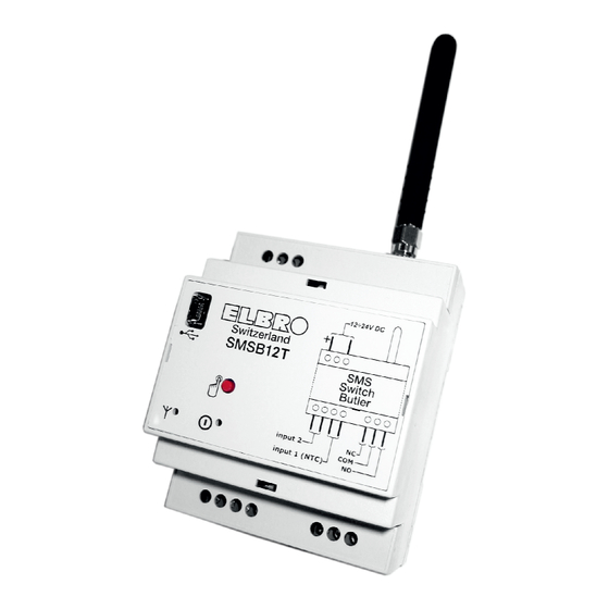
  • Page 21: Schéma De Installation

    SMSB12T - SMS Switch Butler Schéma de installation 12V-24V DC Output: relay Input 2: only digital Input 1: analog/digital Description Alimentation : 12-24V CC – 800 mA Antenne : GSM SMA à deux bandes de fréquences 900-1800 Mhz Port USB pour la programmation par l’intermédiaire d’un ordinateur Bouton pour la communication manuelle de la sortie relais Témoin lumineux (LED) de signalisation d’erreurs et/ou du niveau du signal GSM...
  • Page 22: Insertion De La Carte Sim

    Insertion de la carte SIM Avant d’insérer la carte SIM, il convient de : • DÉSACTIVER le CODE CONFIDENTIEL à l’aide d’un téléphone portable ; • Désactiver le répondeur. Pour insérer la carte SIM dans l’appareil, commencer par retirer le panneau de façade de l’appareil au moyen d’un outil prévu à cet effet : localiser la fente et faire levier pour extraire la façade.
  • Page 23: Programmation Par L'intermédiaire D'un Câble Usb

    Si l’appareil n’est pas reconnu et que le témoin réseau continue à clignoter en rouge, consulter le chapitre consacré à la résolution des pannes. Le logiciel de programmation du SMSB12T est simple, clair et ne nécessite aucune explication. Les prochains chapitres aborderont en détail chacune des fonctions selon l’ordre dans lequel le programme en question les affiche.
  • Page 24: Fonction « Appel Sans Réponse

    Fonction « appel sans réponse » L’appareil est en mesure de mémoriser une liste de numéros de téléphone accompagnés des noms correspondants (jusqu’à trois cent maximum) qui sont habilités à activer et/ou désactiver la sortie relais sur simple appel sans réponse gratuit. Le dispositif reconnait l’appel entrant et le prend immédiatement en charge, tout en activant simultanément l’installation à...
  • Page 25: Commandes Rapides

    SMSB12T - SMS Switch Butler Commande Description Exemple Réponse Mise hors tension de la sortie relais (désactive AUTO) 0000#0 Mise sous tension de la sortie relais (désactive AUTO) 0000#1 Interrogation de l’état actuel 0000#? État actuel Activation de la fonction AUTO.
  • Page 26: Caractéristiques Du Logiciel

    200mA 35mA Déclaration de conformité CE Elbro AG déclare par la présente que le produit SMSB12T est conforme aux conditions essentielles et autres dispositions pertinentes prévues par la directive 199/5/CE, et notamment: EN 301 489-7 V1.1.1 (2000-09) EN 301 511 V7.0.1 (2000-12) EN 60950 (2000) La déclaration de conformité...
  • Page 27 SMSB12T - SMS Switch Butler Indice Informazioni per la sicurezza ....2 Note ........... . . 2 Installazione .
  • Page 28: Informazioni Per La Sicurezza

    Devono inoltre essere rispettate le norme di seguito riportate. Condizioni ambientali Il dispositivo SMSB12T (l’apparecchio e tutti i cavi ad esso connessi) deve essere installato in luoghi privi di , o distanti da: • Polvere, umidità, calore elevato;...
  • Page 29: Schema Di Installazione

    SMSB12T - SMS Switch Butler Schema di installazione 12V-24V DC Output: relay Input 2: only digital Input 1: analog/digital Descrizione Alimentazione: 12-24V DC – 800mA Antenna: GSM SMA dual-band 900-1800Mhz Porta USB per la programmazione tramite PC Pulsante per la commutazione manuale dell’uscita a relè...
  • Page 30: Inserimento Della Sim Card

    Inserimento della sim card Prima di inserire la sim card è necessario: • DISABILITARE il CODICE PIN servendosi di un telefono cellulare; • Disabilitare la segreteria telefonica. Per inserire la sim card nel dispositivo, è necessario rimuovere il pannello frontale del dispositivo, servendosi di un utensile adatto allo scopo: individuare la fessura e fare leva per estrarre il frontalino.
  • Page 31: Programmazione Tramite Cavo Usb

    Nel caso in cui il dispositivo non venisse riconosciuto ed il led rete continuasse a lampeggiare con luce rossa, consultare il capitolo relativo alla risoluzione dei problemi. Il software di programmazione di SMSB12T è semplice, chiaro ed auto esplicativo. Nei prossimi capitoli viene commentato nel dettaglio ciascuna funzione in ordine di visualizzazione del programma in questione.
  • Page 32: Funzione Credito

    Questa funzione (RMODE) può essere configurata secondo le seguenti modalità: • funzione disabilitata; • modalità SWITCH (scambio): viene effettuato il semplice scambio del relè (ON/OFF); (questa modalità disabilità permanentemente la funzione termostato) • modalità PULSE (impulso): viene effettuato un impulso programmabile da uno a venti secondi (questa modalità disabilità permanentemente la funzione termostato);...
  • Page 33: Comandi Rapidi

    SMSB12T - SMS Switch Butler Comando Descrizione Esempio Risposta spegne l'uscita a relè (disattiva AUTO) 0000#0 accende l'uscita a relè (disattiva AUTO) 0000#1 interrogazione sullo stato attuale 0000#? Stato attuale attiva la funzione AUTO. 0000#A Th: 20C Ricorda il valore di soglia precedente; predefinito 20°C attiva la funzione AUTO ed imposta la soglia.
  • Page 34: Requisiti Software

    200mA 35mA Dichiarazione di conformità CE Con la presente Elbro AG dichiara che il prodotto SMSB12T è conforme ai requisiti essenziali ed alle altre disposizioni pertinenti stabilite dalla direttiva 199/5/CE, ed in particolare: EN 301 489-7 V1.1.1 (2000-09) EN 301 511 V7.0.1 (2000-12) EN 60950 (2000) Queste istruzioni per l'uso sono state realizzate con la massima cura.

Table des Matières