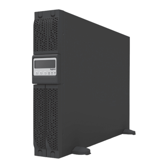
Table des Matières

Publicité

Les langues disponibles
  • FR

Les langues disponibles

  • FRANÇAIS, page 1

Liens rapides

KEOR LINE RT 1000,
®
1500, 2200, 3000 VA
Manuel d'installation
Installation manual
Part. LE07380AD-10/17-01 GF

Publicité

Table des Matières
loading

Sommaire des Matières pour LEGRAND KEOR LINE RT 1000 VA

  • Page 1 KEOR LINE RT 1000, ® 1500, 2200, 3000 VA Manuel d’installation Installation manual • Part. LE07380AD-10/17-01 GF...
  • Page 2 ® KEOR LINE RT 1000, 1500, 2200, 3000 VA FRANÇAIS ENGLISH ITALIANO DEUTSCH ESPAÑOL NEDERLANDS PУСCKИЙ...
  • Page 3: Table Des Matières

    KEOR LINE RT 1000, 1500, 2200, 3000 VA Index 1 Introduction 2 Conditions d’utilisation 3 Afficheur 4 Panneau arrière 5 Installation 6 Logiciel 7 Maintenance 8 Caractéristiques techniques...
  • Page 4: Introduction

    En cas de problème concernant l’ASI, il est recommandé de lire le présent manuel avant de contacter le service d’assistance technique. Assurez-vous de télécharger la dernière version du manuel depuis le site web www.ups.legrand.com 2 Conditions d’utilisation • L’ASI est conçu pour alimenter des appareillages de traitement de données; la charge appliquée ne doit pas dépasser celle indiquée dans l’étiquette sur la partie postérieure de l’ASI.
  • Page 5 KEOR LINE RT 1000, 1500, 2200, 3000 VA • Éviter d’exposer l’ASI à la lumière directe du soleil ou à proximité de toute source de chaleur. • Assurez-vous que l’environnement dans lequel est installé l’onduleur corresponde aux critères de température et humidité demandés ( lire les spécifications techniques) •...
  • Page 6 ® 2 Conditions d’utilisation Stockage Si votre onduleur n’est pas utilisé pour une période prolongée assurez le stockage dans un climat modéré. Les batteries doivent être chargées pendent 12 heures tous les 2 mois en alimentant l’onduleur et en fermant l’interrupteur d’entrée. Répétez cette procédure tous les 2 mois si la température ambiante est supérieure a 25°C.
  • Page 7: Afficheur

    KEOR LINE RT 1000, 1500, 2200, 3000 VA 3 Afficheur LCD 7 1 8 11 6 12 5 13 Voyant secteur Voyant défaut Bouton Marche Bouton Arrêt Batterie à remplacer Fonctionnement sur batteries Batterie basse Bypass Tension secteur basse, onduleur élévateur tension secteur haute , onduleur abaisseur Charge en sortie Erreur de polarité...
  • Page 8: Panneau Arrière

    ® 4 Panneau arrière 1000/1500V A 230V 1000/1500V A 230V 1000/1500V A 230V INPUT INTERFACE CH B INPUT INTERFACE CH B FUNCTION VOLTAGE=220V VOLTAGE=230V VOLTAGE=230V FUNCTION VOLTAGE=240V VOLTAGE=220V VOLTAGE=230V VOLTAGE=230V VOLTAGE=240V 2200/3000V A 230V 2200/3000V A 230V 2200/3000V A 230V 5-1 5-2 5-1 5-2 INPUT...
  • Page 9: Installation

    KEOR LINE RT 1000, 1500, 2200, 3000 VA 5 Installation Déballage Après avoir retiré les protections, vérifier les contenu du paquet standard: • 1 x ASI Keor Line RT • 1 x manuel de l’utilisateur • 1 x cordon d’alimentation •...
  • Page 10 ® 5 Installation Lire attentivement les consignes de sécurité et les conditions d'utilisation écrites dans ce manuel avant d'installer l'onduleur. Si vous installez l'onduleur en configuration tour, lisez la section suivante "Configuration Tour" sinon passer à la section "Configuration rack". Configuration Tour...
  • Page 11 KEOR LINE RT 1000, 1500, 2200, 3000 VA Configuration Rack Step 1 Step 2 Step 3...
  • Page 12 ® 5 Installation Step 4 Step 5...
  • Page 13: Connexion Réseau

    KEOR LINE RT 1000, 1500, 2200, 3000 VA Raccordement de l’ASI Connectez votre onduleur à une prise secteur et ensuite connectez vos charges sur les prises à l’arrière de votre onduleur. Le prise de sortie de l’onduleur Keor Line RT sont secourues par batteries et protégées contre les surtensions.
  • Page 14: Connexion Rs232 /Usb

    ® 5 Installation Connexion RS232 /USB Branchez le câble d’interface ( RS232 ou USB) entre le port situé à l’arrière de l’onduleur et le port d’interface de l’ordinateur. Pour plus d'informations, consultez la section « Logiciel » disponibles dans ce manuel. MISE EN MARCHE Mise en marche de l’onduleur 1.
  • Page 15: Redémarrage Automatique

    KEOR LINE RT 1000, 1500, 2200, 3000 VA Plug-in Charge 1. Si la prise secteur est connectée et le secteur est normal, l’onduleur commencera à se charger automatiquement sans exécution de la procédure de démarrage. 2. La charge doit être effectuée au minimum durant 8 heures tous les 3 mois pour compenser la décharge naturelle des batteries lorsque l’onduleur n’est pas utilisé.
  • Page 16: Logiciel

    ® 6 Logiciel Vérifier la disponibilité et télécharger le logiciel de l'onduleur depuis le site web www.ups.legrand.com. Ce logiciel peut être utilisé pour les fonctions suivantes: - Arrêt automatique de l'ordinateur local connecté a l’onduleur par USB /RS232 - Lecture des paramètres de l’onduleur...
  • Page 17: Maintenance

    • Le service de remplacement des batteries doit être effectué ou supervisé par le personnel expert Legrand, bien formé sur les batteries et les précautions à prendre. • Lors du remplacement des batteries, remplacez-les avec le même type et nombre de batteries incluses dans l'onduleur.
  • Page 18 ® 7 Maintenance de l’onduleur Step 1 Step 2 Step 3...
  • Page 19 KEOR LINE RT 1000, 1500, 2200, 3000 VA 1000/ 1500V A 2200/ 3000V A Recyclage des batteries usagées Contactez votre centre de recyclage des déchets dangereux pour obtenir des informations sur l'élimination correcte de la batterie utilisée.
  • Page 20: Caractéristiques Techniques

    ® 8 Caractéristique techniques 1000VA 1500VA 2200VA 3000VA MODEL NUMBER (3 100 45) (3 100 46) (3 100 47) (3100 48) 1000VA/ 1500VA/ 2200VA/ 3000VA/ Puissance, VA/W 900W 1350W 1980W 2700W Dimensions, L x P x H, in (mm) Appareil 440x405x88 440x650x88 Poids (kg)
  • Page 21: Environnement

    KEOR LINE RT 1000, 1500, 2200, 3000 VA 1000VA 1500VA 2200VA 3000VA MODEL NUMBER (3 100 45) (3 100 46) (3 100 47) (3 100 48) Paramètres batterie Type Etanche au plomb à recombinaison interne Quantité x Tension x Capacité 3x36x7 3x36x9 6x72x7...
  • Page 23 KEOR LINE RT 1000, 1500, 2200, 3000 VA Index 1 Introduction 2 Condition of use 3 LCD Display Panel 4 Rear Panel 5 Installation 6 Software Maintenance 8 Technical features...
  • Page 24: Introduction

    In case of problems with the UPS, please read this manual before contacting the technical support; Please download the latest version of the manual from the website www.ups.legrand.com 2 Condition of use • The UPS has been designed to supply data processing equipment. The load applied must not exceed the one indicated on the rear label of your UPS.
  • Page 25 KEOR LINE RT 1000, 1500, 2200, 3000 VA • Do not expose the UPS to the direct sunlight or any heat sources. • Ensure that the installation site is free from excessive dust and the ambient temperature and humidity are within the specified limits. •...
  • Page 26 ® 2 Condition of use Storage If the UPS is unused for an extended period of time it must be stored in a moderate climate. The batteries should be charged for 12 hours every three months by connecting the UPS to the utility supply and switching on the input breaker located on the UPS rear panel.
  • Page 27: Lcd Display Panel

    KEOR LINE RT 1000, 1500, 2200, 3000 VA 3 LCD Display Panel 7 1 8 11 6 12 5 13 Utility LED Fault LED On Switch Off Switch Battery Replacement Battery Backup LED Battery Low Bypass Utility Low, UPS Boost UPS Output Indicator Polarity Error or Ground Fault Overload...
  • Page 28: Rear Panel

    ® 4 Rear Panel 1000/1500V A 230V 1000/1500V A 230V 1000/1500V A 230V INPUT INTERFACE CH B INPUT INTERFACE CH B FUNCTION VOLTAGE=220V VOLTAGE=230V VOLTAGE=230V FUNCTION VOLTAGE=240V VOLTAGE=220V VOLTAGE=230V VOLTAGE=230V VOLTAGE=240V 2200/3000V A 230V 2200/3000V A 230V 2200/3000V A 230V 5-1 5-2 5-1 5-2 INPUT...
  • Page 29: Installation

    KEOR LINE RT 1000, 1500, 2200, 3000 VA 5 Installation Unpacking After removing the packing foam protections check the following standard package contents : • 1 x UPS Keor Line RT • 1 x Installation/ User Manual • 1 x AC Input Power Cord ( Not available for hard wiring connection models) •...
  • Page 30: Tower Setup

    ® 5 Installation Please read the safety instructions and the conditions of use written in this manual before installing the UPS. If you are installing the UPS in its tower configuration, read the following section “Tower setup” otherwise go to the next section “Rack-Mount setup”. Tower Setup...
  • Page 31 KEOR LINE RT 1000, 1500, 2200, 3000 VA Rack-Mount Setup Step 1 Step 2 Step 3...
  • Page 32 ® 5 Installation Step 4 Step 5...
  • Page 33: Ups Connections

    KEOR LINE RT 1000, 1500, 2200, 3000 VA UPS connections Connect the UPS to a grounded AC power wall outlet using the power cord included in the packaging.Then plug the loads into the outlets available on the rear of the UPS. The UPS outlets provide battery backup and surge protection to the equipment connected.
  • Page 34 ® 5 Installation Computer Interface Port connections Connect the interface cable (RS-232 or USB) between the interface port on the rear of the UPS and the computer interface port. For more information read the software section written in this manual. Operation Turn on the UPS 1.
  • Page 35: Auto-Restart

    KEOR LINE RT 1000, 1500, 2200, 3000 VA Plug-in Charge 1. If the Input Power Cord is connected to the wall receptacle properly and the utility is normal, the UPS will start charging automatically without processing the “Turn On” procedure. 2.
  • Page 36: Software

    ® 6 UPS Software Please verify the availability and download the UPS software tool from the website www.ups.legrand.com. This software can be used for the following functions: - Automatic shutdown of the local computer - UPS parameters reading Communication Port...
  • Page 37: Maintenance

    CAUTION DO NOT DISCONNECT the batteries while the UPS is in the BACKUP mode. • Batteries service must be performed or supervised by Legrand expert personnel knowledgeable about batteries and the required precautions. • When replacing batteries, replace with the same type and number of batteries or battery packs.
  • Page 38 ® 7 UPS Maintenance Step 1 Step 2 Step 3...
  • Page 39: Recycling The Used Battery

    KEOR LINE RT 1000, 1500, 2200, 3000 VA 1000/ 1500V A 2200/ 3000V A Recycling the Used battery Contact your local recycling or hazardous waste center for information on proper disposal of the used battery.
  • Page 40: Technical Features

    ® 8 Technical features 1000VA 1500VA 2200VA 3000VA MODEL NUMBER (3 100 45) (3 100 46) (3 100 47) (3 100 48) 1000VA/ 1500VA/ 2200VA/ 3000VA/ Power Rating, VA/W 900W 1350W 1980W 2700W Dimensions, W x D x H, in (mm) Unit 440x405x88 440x650x88...
  • Page 41 KEOR LINE RT 1000, 1500, 2200, 3000 VA 1000VA 1500VA 2200VA 3000VA MODEL NUMBER (3 100 45) (3 100 46) (3 100 47) (3 100 48) Battery Parameters Type Valve-regulated, nonspillable, lead acid Quantity x Voltage x Rating 3x36x7 3x36x9 6x72x7 6x72x9 Backup Time...
  • Page 43 KEOR LINE RT 1000, 1500, 2200, 3000 VA Indice 1 Introduzione 2 Condizioni di utilizzo 3 Display 4 Pannello posteriore 5 Installazione 6 Software 7 Manutenzione 8 Caratteristiche tecniche...
  • Page 44: Introduzione

    In caso di problemi con l’UPS si consiglia di consultare il presente manuale prima di rivolgersi al servizio di assistenza tecnica. Accertatevi di disporre della versione aggiornata del manuale scaricandola dal sito web www.ups.legrand.com. 2 Condizioni di utilizzo • L’UPS è progettato per alimentare apparecchiature per il trattamento dati ; il carico applicato non deve superare il valore indicato nella targhetta posta nella parte posteriore dell’UPS.
  • Page 45 KEOR LINE RT 1000, 1500, 2200, 3000 VA • Evitare di esporre l’UPS in modo diretto alla luce del sole o di posizionarlo nelle immediate vicinanze di una fonte di calore • Assicuratevi che l’ambiente nel quale è installato il gruppo di continuità corrisponda alle caratteristiche di temperatura e di umidità...
  • Page 46 ® 2 Condizioni di utilizzo Stoccaggio In caso di inutilizzo per un periodo prolungato il gruppo di continuità deve essere conservato a temperatura moderata. Le batterie devono essere caricate per 12 ore ogni 2 mesi alimentando il gruppo di continuità e chiudendo l’interruttore di ingresso.
  • Page 47: Display Lcd

    KEOR LINE RT 1000, 1500, 2200, 3000 VA 3 Display LCD 7 1 8 11 6 12 5 13 Spia di rete Spia di guasto Pulsante di marcia Pulsante di arresto Batteria da sostituire Funzionamento a batterie Batteria bassa Bypass Tensione di rete bassa, UPS Boost Tensione di rete alta, UPS Buck Carico in uscita...
  • Page 48: Pannello Posteriore

    ® 4 Pannello posteriore 1000/1500V A 230V 1000/1500V A 230V 1000/1500V A 230V INPUT INTERFACE CH B INPUT INTERFACE CH B FUNCTION VOLTAGE=220V VOLTAGE=230V VOLTAGE=230V FUNCTION VOLTAGE=240V VOLTAGE=220V VOLTAGE=230V VOLTAGE=230V VOLTAGE=240V 2200/3000V A 230V 2200/3000V A 230V 2200/3000V A 230V 5-1 5-2 5-1 5-2 INPUT...
  • Page 49: Installazione

    KEOR LINE RT 1000, 1500, 2200, 3000 VA 5 Installazione Disimballaggio Dopo avere rimosso le protezioni, verificare il contenuto della confezione standard: • 1 X Kit UPS Keor Line • 1 x manuale d’installazione • 1 x cavo d’alimentazione • 1 x cavo d’uscita IEC (solo modello 1 k / 1,5 kVA) •...
  • Page 50 ® 5 Installazione Leggere con attenzione le prescrizioni di sicurezza e le condizioni di utilizzo riportate nel presente manuale prima di installare il gruppo di continuità. Se l’UPS viene installato in configurazione tower, leggere la sezione seguente “Configurazione tower” altrimenti passare alla sezione “Configurazione rack”. Configurazione Tower...
  • Page 51 KEOR LINE RT 1000, 1500, 2200, 3000 VA Configurazione Rack Fase 1 Fase 2 Fase 3...
  • Page 52 ® 5 Installazione Fase 4 Fase 5...
  • Page 53: Collegamento Dell'ups

    KEOR LINE RT 1000, 1500, 2200, 3000 VA Collegamento dell’UPS Collegare l'UPS a una presa di corrente alternata con protezione di terra utilizzando il cavo incluso nella confezione, successivamente collegate i carichi alla prese nella parte posteriore dell’UPS. Le uscite dell’UPS Keor Line RT forniscono alimentazione di backup e protezione contro le sovratensioni per le apparecchiature collegate.
  • Page 54 ® 5 Installazione Connessione RS232 /USB Tramite il cavo d’interfaccia (RS232 o USB) collegare la porta che si trova nella parte posteriore dell’UPS e la porta d’interfaccia del computer. Per maggiori informazioni consultare la sezione “Software” disponibile nel presente manuale. MESSA IN FUNZIONE Messa in funzione dell’UPS 1 Collegare l’UPS ad una presa a muro.
  • Page 55: Riavvio Automatico

    KEOR LINE RT 1000, 1500, 2200, 3000 VA Plug-in Charge 1 Se la presa di rete è collegata e la rete è normale, l’UPS inizia a caricarsi automaticamente senza eseguire la procedura di avviamento. 2 La carica deve essere effettuata per almeno 8 ore ogni 3 mesi per compensare la scarica naturale delle batterie quando l’UPS non viene utilizzato.
  • Page 56: Software

    ® 6 Software Verificare la disponibilità e scaricare il software dell’UPS dal sito web www.ups.legrand.com. Questo software può essere utilizzato per le seguenti funzioni : - Arresto automatico del computer locale collegato all’UPS tramite USB/RS232 - Lettura dei parametri dell’UPS...
  • Page 57: Sostituzione Delle Batterie

    Non scollegare le batterie quando l’UPS è in modalità a batteria • Il servizio di sostituzione batterie va effettuato oppure supervisionato da personale esperto Legrand, adeguatamente formato sulle batterie e sulle precauzioni da adottare. • Quando si sostituiscono le batterie esse vanno sempre rimpiazzate con altre dello stesso tipo e nella stessa quantità...
  • Page 58 ® 7 Manutenzione del gruppo di continuità Fase 1 Fase 2 Fase 3...
  • Page 59 KEOR LINE RT 1000, 1500, 2200, 3000 VA 1000/ 1500V A 2200/ 3000V A Smaltimento delle batterie usate Contattare il vostro centro di riciclaggio o di gestione rifiuti pericolosi locale per ottenere informazioni riguardanti il corretto smaltimento delle batterie usate...
  • Page 60: Caratteristiche Tecniche

    ® 8 Caratteristiche tecniche 1000VA 1500VA 2200VA 3000VA NUMERO MODELLO (3 100 45) (3 100 46) (3 100 47) (3100 48) 1000VA/ 1500VA/ 2200VA/ 3000VA/ Potenza, VA/W 900W 1350W 1980W 2700W Dimensioni, L x P x H in (mm) Apparecchio 440x405x88 440x650x88 Peso (kg)
  • Page 61 KEOR LINE RT 1000, 1500, 2200, 3000 VA 1000VA 1500VA 2200VA 3000VA NUMERO MODELLO (3 100 45) (3 100 46) (3 100 47) (3 100 48) Parametri batteria Ermetiche, al piombo a ricombinazione interna, Tipo regolate tramite valvola Quantità x Tensione x Capacità 3x36x7 3x36x9 6x72x7...
  • Page 63 KEOR LINE RT 1000, 1500, 2200, 3000 VA Inhaltsverzeichnis 1 Einleitung 2 Anwendungsbedingungen 3 Display 4 Hintere Tafel 5 Installation 6 Software 7 Wartung der unterbrechungsfreien Stromversorgung 8 Technische Daten...
  • Page 64: Einleitung

    Sie die Anweisungen des Handbuchs genau. Sollten Störungen an der USV-Einheit auftreten, empfehlen wir dieses Handbuch aufmerksam durchzulesen bevor Sie den technischen Kundendienst anrufen. Vergewissern Sie sich, dass Sie über die neuste Handbuchausgabe verfügen, die Sie von der Website www.ups.legrand.com. herunterladen können. 2 Anwendungsbedingungen •...
  • Page 65 KEOR LINE RT 1000, 1500, 2200, 3000 VA • Verschütten Sie keine Flüssigkeiten über oder in die USV. • Die unterbrechungsfreie Stromversorgung nicht in feuchten Umgebungen oder in der Nähe von Flüssigkeiten installieren (Wasser, chemische Lösungen usw.). • Setzen Sie die USV keinem direkten Sonnenlicht aus und vermeiden Sie die Nähe zu Wärmequellen.
  • Page 66 ® 2 Anwendungsbedingungen Lagerung Falls die unterbrechungsfreie Stromversorgung längere Zeit nicht verwendet wird, diese bei mäßiger Temperatur lagern. Die Batterien müssen alle 2 Monate 12 Stunden lang aufgeladen werden. Dabei muss die unterbrechungsfreie Stromversorgung gespeist und der Eingangsschalter ausgeschaltet werden. Den Vorgang alle 2 Monate wiederholen, wenn die Umgebungstemperatur mehr als 25°C beträgt.
  • Page 67: Lcd Display

    KEOR LINE RT 1000, 1500, 2200, 3000 VA 3 LCD-Display 7 1 8 11 6 12 5 13 Netz-Meldeleuchte Fehler-Meldeleuchte Betriebstaste Stopptaste Batterie auswechseln Batteriebetrieb Batterie niedrig Bypass Niedrige Netzspannung, USV Boost Hohe Netzspannung, USV Buck Stromlast am Ausgang Polaritäts- oder Erdungsfehler Überlast Stromlast in Prozent am Ausgang / Ladezustand der Batterien (%) Taste zum Übergag von Stromlast in Prozent...
  • Page 68: Hintere Tafel

    ® 4 Hintere Tafel 1000/1500V A 230V 1000/1500V A 230V 1000/1500V A 230V INPUT INTERFACE CH B INPUT INTERFACE CH B FUNCTION VOLTAGE=220V VOLTAGE=230V VOLTAGE=230V FUNCTION VOLTAGE=240V VOLTAGE=220V VOLTAGE=230V VOLTAGE=230V VOLTAGE=240V 2200/3000V A 230V 2200/3000V A 230V 2200/3000V A 230V 5-1 5-2 5-1 5-2 INPUT...
  • Page 69: Installation

    KEOR LINE RT 1000, 1500, 2200, 3000 VA 5 Installation Auspacken Die Schutzelemente entfernen und den Inhalt der Standardpackung kontrollieren: • 1 X Set USV Keor Line • 1 x Installationsanweisungen • 1 x Speisekabel • 1 x Ausgangskabel IEC (nur Modell 1 k / 1,5 kVA) •...
  • Page 70 ® 5 Installation Die Sicherheitsvorschriften und Betriebsbedingungen, die im vorliegenden Handbuch enthalten sind, aufmerksam lesen, bevor die unterbrechungsfreie Stromversorgung verwendet wird. Wenn die USV in der Konfiguration Tower installiert wird, nachfolgenden Abschnitt „Tower- Konfiguration“ lesen, ansonsten auf Abschnitt „Rack-Konfiguration“ übergehen. Tower-Konfiguration...
  • Page 71 KEOR LINE RT 1000, 1500, 2200, 3000 VA Rack-Konfiguration Phase 1 Phase 2 Phase 3...
  • Page 72 ® 5 Installation Phase 4 Phase 5...
  • Page 73 KEOR LINE RT 1000, 1500, 2200, 3000 VA USV-Anschluss Die USV an eine Strombuchse mit Wechselstrom und Erdung mit Hilfe des mitgelieferten Kabels und dann die Stromlasten an die Buchsen an der Rückseite der USV anschließen. Die Ausgänge der USV Keor Line RT liefern die Notstromversorgung und Schutz der angeschlossenen Geräte gegen Überspannungen.
  • Page 74 ® 5 Installation RS232 /USB Anschluss Das Kabel der Schnittstelle (RS232 oder USB) an den Port an der Rückseite der USV und an den Port des Computers anschließen. Für weitere Informationen, siehe Abschnitt „Software“ im vorliegenden Handbuch. INBETRIEBNAHME Inbetriebnahme der USV 1 Die USV an eine Wandbuchse anschließen.
  • Page 75 KEOR LINE RT 1000, 1500, 2200, 3000 VA Plug-in Charge 1 Wenn die Buchse des Stromnetzes angeschlossen und normal ist, wird die USV automatisch und ohne Inbetriebnahme aufgeladen. 2 Die Batterie muss mindestens alle 3 Monate 8 Stunden lang aufgeladen werden, um die natürliche Erschöpfung (bei Nichtbenutzung) auszugleichen.
  • Page 76: Software

    ® 6 Software Sie können die Software der USV von der Website www.ups.legrand.com. herunterladen, Diese Software kann für folgende Funktionen verwendet werden: - Automatisches Abschalten des lokalen Computers, der über den RS232 an die USV angeschlossen ist. - Ablesen der USV-Parameter...
  • Page 77: Wartung Der Unterbrechungsfreien Stromversorgung

    ACHTUNG Die Batterien nicht abtrennen, wenn die USV auf Batteriebetrieb geschaltet ist. • Die Batterien dürfen nur von Fachleuten von Legrand ausgewechselt oder gewartet werden. Das Personal muss zweckmäßig geschult und über die Vorsichtsmaßnahmen informiert sein. • Wenn die Batterien ausgewechselt werden, müssen sie durch andere desselben Typs und in derselben Anzahl ersetzt werden.
  • Page 78 ® 7 Wartung der unterbrechungsfreien Stromversorgung Phase 1 Phase 2 Phase 3...
  • Page 79 KEOR LINE RT 1000, 1500, 2200, 3000 VA 1000/ 1500V A 2200/ 3000V A Erschöpfte Batterien entsorgen Rufen Sie die zuständige Entsorgungsstelle oder die Stelle für gefährliche Abfälle an, um weitere Informationen zur sachgerechten Entsorgung der erschöpften Batterien zu erhalten.
  • Page 80: Technische Daten

    ® 8 Technische Daten 1000VA 1500VA 2200VA 3000VA MODELLNUMMER (3 100 45) (3 100 46) (3 100 47) (3100 48) 1000VA/ 1500VA/ 2200VA/ 3000VA/ Leistung, VA/W 900W 1350W 1980W 2700W Abmessung (H x L x T) (mm) Gerät 440x405x88 440x650x88 Gewicht (kg) Gerät Eingangsparameter NO...
  • Page 81 KEOR LINE RT 1000, 1500, 2200, 3000 VA 1000VA 1500VA 2200VA 3000VA MODELLNUMMER (3 100 45) (3 100 46) (3 100 47) (3 100 48) Batterieparameter Verschlossene gasdichte und ventilgesteuerte Bleibatterien Menge x Spannung x Leistung 3x36x7 3x36x9 6x72x7 6x72x9 Autonomie 50% Ladung >10’...
  • Page 83 KEOR LINE RT 1000, 1500, 2200, 3000 VA Tabla de contenidos 1 Introducción 2 Condiciones de uso 3 Display 4 Panel trasero 5 Instalación 6 Software 7 Mantenimiento 8 Características técnicas...
  • Page 84: Introducción

    En caso de problemas con el SAI se aconseja consultar el presente manual antes de acudir al servicio de asistencia técnica. Comprobar que se tenga a disposición la versión actualizada del manual descargándola de la página web www.ups.legrand.com. 2 Condiciones de uso •...
  • Page 85 KEOR LINE RT 1000, 1500, 2200, 3000 VA • Evitar exponer el SAI de forma directa a la luz del sol o posicionarlo muy cerca de una fuente de calor. • Comprobar que el ambiente en que se instala el grupo de continuidad corresponda a las características de temperatura y de humedad que se requieren (leer las especificaciones técnicas).
  • Page 86: Almacenamiento

    ® 2 Condiciones de uso Almacenamiento En caso de inutilización durante un período prolongado, el grupo de continuidad tiene que conservarse a una temperatura moderada. Las baterías tienen que cargarse durante 12 horas cada 2 meses alimentando el grupo de continuidad y cerrando el interruptor de entrada.
  • Page 87: Display

    KEOR LINE RT 1000, 1500, 2200, 3000 VA 3 Display LCD 7 1 8 11 6 12 5 13 Indicador luminoso de red Indicador luminoso de avería Pulsador de Marcha Pulsador de Parada Batería a sustituir Funcionamiento de baterías Batería baja Bypass Tensión eléctrica de red baja, UPS Boost Tensión eléctrica de red alta, UPS Buck...
  • Page 88: Panel Trasero

    ® 4 Panel trasero 1000/1500V A 230V 1000/1500V A 230V 1000/1500V A 230V INPUT INTERFACE CH B INPUT INTERFACE CH B FUNCTION VOLTAGE=220V VOLTAGE=230V VOLTAGE=230V FUNCTION VOLTAGE=240V VOLTAGE=220V VOLTAGE=230V VOLTAGE=230V VOLTAGE=240V 2200/3000V A 230V 2200/3000V A 230V 2200/3000V A 230V 5-1 5-2 5-1 5-2 INPUT...
  • Page 89: Instalación

    KEOR LINE RT 1000, 1500, 2200, 3000 VA 5 Instalación Desembalaje Después de haber quitado las protecciones, controlar el contenido del paquete estándar: • 1 X Kit SAI Keor Line • 1 x manual de instalación • 1 x cable de alimentación •...
  • Page 90 ® 5 Instalación Leer con atención las prescripciones de seguridad y las condiciones de uso que se encuentran en el presente manual antes de instalar el grupo de continuidad. Si el SAI se instala en configuración tower, leer la sección siguiente “Configuración tower”; de lo contrario pasar a la sección “Configuración rack”.
  • Page 91 KEOR LINE RT 1000, 1500, 2200, 3000 VA Configuración Rack Fase 1 Fase 2 Fase 3...
  • Page 92 ® 5 Instalación Fase 4 Fase 5...
  • Page 93: Conexión De Red

    KEOR LINE RT 1000, 1500, 2200, 3000 VA Conexión del SAI Conectar el SAI a una toma de corriente alterna con protección de tierra utilizando el cable que se incluye en el paquete; sucesivamente conectar las cargas a las tomas de corriente que se encuentran en la parte trasera del SAI.
  • Page 94: Puesta En Función

    ® 5 Instalación Conexión RS232/USB A través del cable de interfaz (RS232 o USB) conectar el puerto que se encuentra en la parte trasera del SAI y el puerto de interfaz del ordenador. Para más información consultar la sección “Software” que está...
  • Page 95 KEOR LINE RT 1000, 1500, 2200, 3000 VA Plug-in Charge 1 Si la toma de corriente de red se ha conectado y la red es normal, el SAI empieza a cargarse automáticamente sin ejecutar el procedimiento de arranque. 2 La carga tiene que realizarse durante por lo menos 8 horas cada 3 meses, para compensar la descarga natural de las baterías cuando el SAI no se utilice.
  • Page 96: Software

    - Lectura de los parámetros del SAI. Comunicación Conector DB-9 El SAI posee un conector DB-9 (hembra, 9 polos) en la parte trasera, que permite la comunicación entre el mismo SAI y el software Legrand. Asignación polo Collector to Emitter* Colector...
  • Page 97: Mantenimiento

    No desconectar las baterías cuando el SAI se encuentra en modalidad baterías. • El servicio de sustitución de las baterías tiene que ser realizado o bien supervisado por personal experto Legrand, adecuadamente formado sobre las baterías y sobre las precauciones que hay que adoptar.
  • Page 98 ® 7 Mantenimiento del SAI Fase 1 Fase 2 Fase 3...
  • Page 99 KEOR LINE RT 1000, 1500, 2200, 3000 VA 1000/ 1500V A 2200/ 3000V A Eliminación de las baterías usadas Contactar el centro de reciclaje o de gestión de residuos peligrosos local para obtener información acerca de la eliminación correcta de las baterías usadas.
  • Page 100: Características Técnicas

    ® 8 Características técnicas 1000VA 1500VA 2200VA 3000VA NÚMERO DE MODELO (3 100 45) (3 100 46) (3 100 47) (3100 48) 1000VA/ 1500VA/ 2200VA/ 3000VA/ Potencia, VA /W 900W 1350W 1980W 2700W Dimensiones, L x P x H in (mm) Aparato 440x405x88 440x650x88...
  • Page 101 KEOR LINE RT 1000, 1500, 2200, 3000 VA 1000VA 1500VA 2200VA 3000VA NÚMERO DE MODELO (3 100 45) (3 100 46) (3 100 47) (3 100 48) Parámetros de la batería Herméticas, de plomo de recombinación interna, Tipo reguladas mediante válvula Cantidad x Tensión x Capacidad 3x36x7 3x36x9...
  • Page 103 KEOR LINE RT 1000, 1500, 2200, 3000 VA Index 1 Inleiding 2 Gebruiksvoorwaarden 3 Scherm 4 Achterpaneel 5 Installatie 6 Software 7 Onderhoud 8 Technische kenmerken...
  • Page 104: Inleiding

    Raadpleeg deze handleiding als u problemen ondervindt met de UPS alvorens de technische dienst te contacteren. Download de laatste versie van de handleiding op de website www.ups.legrand.com. 2 Gebruiksvoorwaarden • De UPS is bedoeld om gegevensverwerkende apparatuur te voeden. De belasting mag niet ho- ger zijn dan die aangegeven op het label aan de achterkant van de UPS.
  • Page 105 KEOR LINE RT 1000, 1500, 2200, 3000 VA • Stel de UPS niet bloot aan direct zonlicht of warmtebronnen. • Zorg ervoor dat de omgeving waarin de UPS wordt geïnstalleerd, vrij is van stof en voldoet aan de criteria voor temperatuur en vochtigheidsgraad, binnen de gestelde grenzen. •...
  • Page 106 ® 2 Gebruiksvoorwaarden Opslag Bewaar de UPS op een plaats met een gematigd klimaat als u hem gedurende langere periode niet gebruikt. Laad de batterijen om de drie maanden op gedurende 12 uur, door de UPS te voeden en de in- gangsschakelaar te sluiten, die zich bevind op het acterpaneel.
  • Page 107: Scherm

    KEOR LINE RT 1000, 1500, 2200, 3000 VA 3 LCD-scherm 7 1 8 11 6 12 5 13 Controle LED elektriciteitsnet Alarm LED Knop ‘aan’ Knop ‘uit’ Batterij vervangen LED indicatie werking op batterijen Zwakke batterij Bypass Lage netspanning, UPS verhoogt spanning Hoge netspanning, UPS verlaagt spanning Belasting aan uitgang Fout in polariteit of aarding...
  • Page 108: Achterpaneel

    ® 4 Achterpaneel 1000/1500V A 230V 1000/1500V A 230V 1000/1500V A 230V INPUT INTERFACE CH B INPUT INTERFACE CH B FUNCTION VOLTAGE=220V VOLTAGE=230V VOLTAGE=230V FUNCTION VOLTAGE=240V VOLTAGE=220V VOLTAGE=230V VOLTAGE=230V VOLTAGE=240V 2200/3000V A 230V 2200/3000V A 230V 2200/3000V A 230V 5-1 5-2 5-1 5-2 INPUT OUTPUT...
  • Page 109: Installatie

    KEOR LINE RT 1000, 1500, 2200, 3000 VA 5 Installatie Uitpakken Verwijder de beschermingen en controleer de inhoud van het standaardpakket: • 1 x UPS Keor Line RT • 1 x handleiding • 1 x AC voedingskabel (niet beschikbaar voor modellen die vast aangesloten worden) •...
  • Page 110 ® 5 Installatie Lees aandachtig de veiligheidsvoorschriften en de gebruiksvoorwaarden in deze handleiding al- vorens de UPS te installeren. Lees het volgende hoofdstuk ‘Installeren als tower’ als u de UPS als tower wilt installeren. Ga anders door naar het hoofdstuk ‘Installeren in rack’ . Installeren als tower...
  • Page 111 KEOR LINE RT 1000, 1500, 2200, 3000 VA Installeren in rack Stap 1 Stap 2 Stap 3...
  • Page 112 ® 5 Installatie Stap 4 Stap 5...
  • Page 113 KEOR LINE RT 1000, 1500, 2200, 3000 VA De UPS aansluiten Sluit de UPS aan op een contactdoos van het elektriciteitsnet en sluit vervolgens de belastingen aan op de contactdozen aan de achterkant van de UPS. De uitgangen van de Keor Line RT zijn ondersteund door batterijen en beschermd tegen over- spanning.
  • Page 114 ® 5 Installatie Computer interface poort aansluitingen Breng de interfacekabel (RS232 of USB) aan tussen de poort aan de achterkant van de UPS en de interfacepoort van de computer. Raadpleeg voor meer informatie het hoofdstuk ‘Software’ in deze handleiding. WERKING Schakel de UPS in.
  • Page 115 KEOR LINE RT 1000, 1500, 2200, 3000 VA Opladen 1. Als de ingangskabel correct aangesloten is op de contactdoos en de voedingsspanning normaal is, zal de UPS automatisch starten met het opladen zonder de “Turn on” modus uit te voeren. 2.
  • Page 116: Software

    De UPS uitgerust met een vrouwelijke DB-9-connector met 9 pinnen, voor de communicatie tussen de UPS en de computer waarop de software van Legrand draait. Deze connector bevind zich op het achterpaneel van de UPS. De connectie voorziet seriële communicatie, batterij “On” en batterij “Low”...
  • Page 117: De Batterijen Vervangen

    Koppel de batterijen niet los terwijl de UPS op batterij werkt. • De batterijen moeten worden vervangen door of onder toezicht van bevoegd personeel van Legrand, dat vertrouwd is met de batterijen en de te nemen voorzorgsmaatregelen. • Vervang de batterijen door hetzelfde aantal batterijen van hetzelfde type.
  • Page 118 ® 7 Onderhoud van de UPS Stap 1 Stap 2 Stap 3...
  • Page 119 KEOR LINE RT 1000, 1500, 2200, 3000 VA 1000/ 1500V A 2200/ 3000V A Recycling van afgedankte batterijen Neem contact op met uw recyclingcentrum voor gevaarlijk afval voor meer informatie over de correcte afvoering van afgedankte batterijen.
  • Page 120: Technische Kenmerken

    ® 8 Technische kenmerken 1000VA 1500VA 2200VA 3000VA MODELNUMMER (3 100 45) (3 100 46) (3 100 47) (3100 48) 1000VA/ 1500VA/ 2200VA/ 3000VA/ Vermogen, VA/W 900W 1350W 1980W 2700W Afmetingen, L x B x H (mm) Apparaat 440x405x88 440x650x88 Gewicht (kg) Apparaat Parameters van AC-ingang...
  • Page 121 KEOR LINE RT 1000, 1500, 2200, 3000 VA 1000VA 1500VA 2200VA 3000VA MODELNUMMER (3 100 45) (3 100 46) (3 100 47) (3 100 48) Parameters batterij Verzegelde loodzuurbatterij met interne recombinatie Type (VRLA) Aantal x Spanning x Capaciteit 3x36x7 3x36x9 6x72x7 6x72x9...
  • Page 123 ИБП KEOR LINE RT 1000, 1500, 2200, 3000 Содержание 1 Введение 2 Меры безопасности 3 Панель управления с ЖК дисплеем 4 Задняя панель 5 Монтаж 6 Программное обеспечение ИБП 7 Техническое обслуживание ИБП 8 Технические характеристики...
  • Page 124: Введение

    Перед тем, как обращаться в службу технической поддержки при возникновении проблем с ИБП, выполните все проверки, описанные в настоящем документе. Новейшую версию этого документа можно скачать на сайте www.ups.legrand.com. 2 Меры безопасности • ИБП предназначен для обеспечения бесперебойным питанием оборудования для...
  • Page 125 ИБП KEOR LINE RT 1000, 1500, 2200, 3000 • Не помещайте ИБП под прямыми лучами солнца или вблизи источников тепла. • Убедитесь, что атмосфера на месте установки не является сильно запыленной, а температура и влажность воздуха находятся в допустимых пределах. •...
  • Page 126 ® 2 Правила хранения Хранение Длительное хранение ИБП разрешается при умеренной температуре. Батареи следует заряжать в течение 12 часов каждые 12 месяцев, подключив ИБП к электросети и включив вводной выключатель на задней панели ИБП. При температуре хранения более 25 °C повторяйте...
  • Page 127: Панель Управления С Жк Дисплеем

    ИБП KEOR LINE RT 1000, 1500, 2200, 3000 3 Панель управления с ЖК дисплеем 7 1 8 11 6 12 5 13 Светодиодный индикатор СЕТЬ Светодиодный индикатор НЕИСПРАВНОСТЬ Кнопка ON (ВКЛ.) Кнопка OFF (ОТКЛ.) Замена батареи Светодиодный индикатор работы в автономном режиме Низкий...
  • Page 128: Задняя Панель

    ® 4 Задняя панель 1000/1500V A 230V 1000/1500V A 230V 1000/1500 ВА 230 В INPUT INTERFACE CH B INPUT INTERFACE CH B FUNCTION VOLTAGE=220V VOLTAGE=230V VOLTAGE=230V FUNCTION VOLTAGE=240V VOLTAGE=220V VOLTAGE=230V VOLTAGE=230V VOLTAGE=240V 2200/3000V A 230V 2200/3000 ВА 230 В 2200/3000V A 230V 5-1 5-2 5-1 5-2 INPUT...
  • Page 129: Монтаж

    ИБП KEOR LINE RT 1000, 1500, 2200, 3000 5 Монтаж Распаковка Освободите ИБП от защиты из пенопласта и проверьте состав комплекта: • 1 ИБП Keor Line RT • 1 Руководство по монтажу и эксплуатации • 1 входной шнур питания для подключения к сети переменного тока (кроме моделей с входными...
  • Page 130: Монтаж В Вертикальном Положении

    ® 5 Монтаж Перед тем как устанавливать ИБП, внимательно изучите меры безопасности и требования к установке, содержащиеся в данном Руководстве. При установке ИБП в конфигурации "башня" изучите требования раздела "Монтаж в вертикальном положении". При установке ИБП в конфигурации "стойка" изучите требования раздела...
  • Page 131 ИБП KEOR LINE RT 1000, 1500, 2200, 3000 Монтаж в горизонтальном положении Шаг 1 Шаг 2 Шаг 3...
  • Page 132 ® 5 Монтаж Шаг 4 Шаг 5...
  • Page 133 ИБП KEOR LINE RT 1000, 1500, 2200, 3000 Подключение ИБП С помощью входного шнура питания из комплекта поставки подключите ИБП к сетевой розетке, оборудованной контактом заземления. Затем подключите нагрузки к выходным розеткам сзади ИБП. Выходы ИБП обеспечивают бесперебойное питание нагрузок за счет использования батарей и...
  • Page 134: Работа С Ибп

    ® 5 Монтаж Подключение к портам компьютера Соедините кабелем связи (RS-232 или USB) соответствующие порты на задних панелях ИБП и компьютера. Более подробная информация приведена ниже в разделе, посвященном программному обеспечению. Работа с ИБП Включение ИБП 1 Подключите ИБП к сети переменного тока. Если напряжение сети в норме, то ЖК дисплей будет...
  • Page 135 ИБП KEOR LINE RT 1000, 1500, 2200, 3000 Встроенное зарядное устройство 1 Если входной шнур питания подключен к сетевой розетке и напряжение сети в норме, то ИБП заряжается автоматически, не требуя выполнения процедуры включения. 2 Если ИБП не подключен к сети, то для предотвращения естественного разряда батареи ее следует...
  • Page 136: Программное Обеспечение Ибп

    -Считывание параметров ИБП Порт связи Разъем DB-9 для связи с компьютером, на котором установлено специальное ПО управления ИБП Legrand. Данное последовательное соединение обеспечивает обмен данными и подачу сигнавов "Работа в автономном режиме" и "Батарея разряжена". ИБП имеет разъем DB-9 (9-контактная розетка) на задней панели...
  • Page 137: Техническое Обслуживание Ибп

    ЗАПРЕЩАЕТСЯ ОТСОЕДИНЯТЬ БАТАРЕИ, пока ИБП работает в АВТОНОМНОМ РЕЖИМЕ. • Работы с батареями разрешается выполнять подготовленным сервисным специалистам Legrand при соблюдении надлежащих мер безопасности. • Новые батареи должны быть такого же типа и в таком же количестве, как заменяемые. • Запрещается бросать батареи в огонь, они могут взорваться! •...
  • Page 138 ® 7 Техническое обслуживание ИБП Шаг 1 Шаг 2 Шаг 3...
  • Page 139 ИБП KEOR LINE RT 1000, 1500, 2200, 3000 1000/1500 ВА 2200/3000 ВА Утилизация использованных батарей По поводу утилизации использованных батареи обратитесь в соответствующую организацию по месту эксплуатации.
  • Page 140: Технические Характеристики

    ® 8 Технические характеристики 1000 ВА 1500BA 2200BA 3000BA НОМЕР МОДЕЛИ (3 100 45) (3 100 46) (3 100 47) (3100 48) 1000 ВА/ 1500 ВА/ 2200 ВА/ 3000 ВА/ Номинальная мощность 900 Вт 1350 Вт 1980 Вт 2700 Вт Размеры, Ш...
  • Page 141 ИБП KEOR LINE RT 1000, 1500, 2200, 3000 1000 ВА 1500 ВА 2200 ВА 3000 ВА НОМЕР МОДЕЛИ (3 100 45) (3 100 46) (3 100 47) (3 100 48) Характеристики батареи Герметичная свинцово-кислотная с регулирующим Тип клапаном Количество аккумуляторов х 3x36x7 3x36x9 6x72x7...
  • Page 142 Notes...
  • Page 144 : 33 5 55 06 87 87 Fax : 33 5 55 06 74 55 www.legrandelectric.com Legrand se réserve le droit de modifier à tout moment le contenu de cet imprimé et de communiquer, sous n’importe quelle forme et modalité, les changements apportés.

Ce manuel est également adapté pour:

Keor line rt 1500 vaKeor line rt 2200 vaKeor line rt 3000 va

Table des Matières