Publicité

Les langues disponibles

Les langues disponibles

Liens rapides

3
4
Laser FF 95
MANUEL D'UTILISATION
OPERATING INSTRUCTIONS
GEBRUIKSAANWIJZING
3
26
49

Publicité

Table des Matières
loading

Sommaire des Matières pour Zibro Laser FF 95

  • Page 1 Laser FF 95 MANUEL D’UTILISATION OPERATING INSTRUCTIONS GEBRUIKSAANWIJZING...
  • Page 2: En Cas De Doute, Contactez Votre Revendeur Zibro

    A condition, bien sûr, de respecter les consignes d'utilisation. C'est pourquoi nous vous invitons vivement à consulter ce manuel afin d'assurer à votre appareil Zibro Laser une durée de vie optimale. Les produits Zibro sont garantis contre tout vice de fabrication ou de concep- tion (hors consommables) pendant une durée de 4 ans à...
  • Page 3: Ce Que Vous Devez Savoir Au Préalable

    CE QUE VOUS DEVEZ SAVOIR AU PRÉALABLE: LE BON COMBUSTIBLE Votre poêle Zibro est conçu pour être utilisé avec un pétrole non aqueux de haute qualité, comme Zibro Extra ou Zibro Kristal. Seuls les combustibles de ce type garantissent une combustion efficace et propre. Les combustibles de qualité...
  • Page 4 Chapitre 1: INSTALLATION 1. Introduction Outils conseillés: Ce chapitre contient des informations concernant: 1. Tournevis cruciforme 2. Mètre métallique • Spécifications pour l’installation 3. Feutre ou crayon • Liste des outils nécessaires à l’installation 4. Ciment pour extérieur • Exigences minimums pour l’installation du réservoir 5.
  • Page 5 Chapitre 1: INSTALLATION 5. Fils du capteur de température ambiante 6. Sortir l’appareil de l’emballage Le capteur de température peut être fixé sur un mur. Il Conservez l’emballage de votre appareil pour une utili- mesure la température ambiante pour réguler automa- sation ultérieure éventuelle.
  • Page 6 Chapitre 1: INSTALLATION Objet inflammable Objet inflammable Pas moins de 60 cm Pas moins de 45 cm Pas moins Objet non- de 45 cm inflammable Pas moins de 60 cm 45°C Pas moins de 30 cm Pas moins de 30 cm Tuyau d’évacuation Pas moins de 20 cm* * Ce dispositif doit également être présent en cas de chutes de neige, etc.
  • Page 7 Chapitre 1: INSTALLATION Percez le trou pour le tuyau d’évacuation à l’aide du gabarit, puis installez le Laser comme indiqué par les illustrations. Si vous ne possédez plus le gabarit de perçage ou si le poêle doit être déplacé, voici les dimensions à respecter pour les trous du tuyau de combustible et le tuyau d’é- vacuation.
  • Page 8 Chapitre 1: INSTALLATION Pièces standard nécessaires à l’installation Les pièces standard indiquées ci-dessous sont fournies avec le poêle. Si vous installez votre poêle selon une autre procédure, vous devrez peut-être commander d’autres pièces. Plaque de fond (1) Crochets muraux (2 jeux) Porte tuyau (1) Fixation de tuyauterie (1) Tuyau d’évacuation (1)
  • Page 9 Chapitre 1: INSTALLATION Goulotte de trop-plein (1) Tuyau d’air coudé (2) Tuyau d’air souple (1) Pince à tuyau souple (2)
  • Page 10 Chapitre 1: INSTALLATION 1. Pour une installation standard, utilisez le gabarit tion au bon endroit. Fixez le gabarit sur le mur à l’aide fourni pour placer le trou destiné au tuyau d’évacua- de ruban adhésif ou de petits clous (voir fig. 4). Ruban adhésif Fig.
  • Page 11 Chapitre 1: INSTALLATION 3a. Pour des murs avec une épaisseur de 230-320 mm: Introduisez le conduit d’évacuation d’air dans le trou depuis l’intérieur. Assurez-vous que la flèche de la partie intérieure du conduit d’air est orientée vers le haut. Fixez la partie intérieure du conduit d’air au mur à l’aide des trois vis à...
  • Page 12 Chapitre 1: INSTALLATION 3c. Introduisez le conduit d’évacuation d’air dans le trou depuis l’extérieur. Fixez le conduit d’évacuation d’air extérieure au mur en la tournant vers la droite. Les deux parties seront ainsi connectées (voir fig. 9). Remarque: Assurez-vous que la flèche sur le bord surélevé (bride) de la partie extérieure du conduit d’air est orien- tée vers le haut.
  • Page 13 Chapitre 1: INSTALLATION 5. Posez l’appareil à sa place. Fixez le tuyau d’évacua- tuyau d’air coudé sur l’entrée. Vérifiez que tout est soli- tion coudé sur la sortie (l’ouverture du haut) et fixez le dement fixé (voir fig. 11). Tuyau d’évacuation coudé Sortie Entrée Tuyau d’air coudé...
  • Page 14 Chapitre 1: INSTALLATION 8. Assurez-vous que le chauffage est de niveau, en util- n’est pas dans le cercle, ajustez les pieds du chauffage isant le fil à plomb du bon côté du chauffage Le poids jusqu’à ce que le poids soit dans le cercle rouge (voir ill. du fil à...
  • Page 15: Liste De Controle

    Chapitre 1: INSTALLATION LISTE DE CONTROLE Possibilités d’alimentation en combustible • Vérifiez si l’appareil est branché à une prise L’alimentation en combustible du Laser 95 peut se faire électrique adéquate. de la façon suivante: • Vérifiez qu’une quantité suffisante de combustible se trouve dans le réservoir de combustible.
  • Page 16 Chapitre 1: INSTALLATION purge d’air et le remplissage s’effectue par la même ouverture. Important Veillez à ce que les tuyaux de combustible soient propres. Des éventuelles saletés peuvent causer des problèmes dans le bac de récupération de com- bustible. La tuyauterie de combustible doit être en cuivre avec un diamètre extérieur de 3/8”.
  • Page 17: Chapitre 2, Utilisation

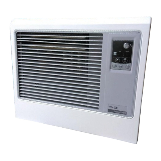
    Chapitre 2, UTILISATION 1. Introduction Le Laser FF 95 est un appareil ventilé à combustible facile à utiliser. Il a une importante puissance de chauffage et présente une régulation automatique de la température ambiante, une faible consommation de combustible et d’électricité et peut être utilisé en mode automatique ou manuel.
  • Page 18 Chapitre 2, UTILISATION 3. Touches de commandes et voyants lumineux 1. Bouton ON/OFF 3. Écran 2. Adjustment buttons 2. Boutons de réglage (time and temperature) 4. Save button 4. Bouton de sécurité (SAVE): 5. Timer button 5. Bouton minuterie 6. Bouton sécurité enfant (childproof lock): Fig.
  • Page 19 Chapitre 2, UTILISATION 4. Avant la première utilisation ture ambiante enregistrée par le capteur dans la pièce. Étape 1: Ouvrez le(s) couvercle(s) Ouvrez le couvercle pour le réservoir de combustible Étape 1: Allumez l’appareil extérieur et le robinet anti-feu (s’il est présent). Mettez le bouton ON/OFF en position “ON”...
  • Page 20 Chapitre 2, UTILISATION mode de fonctionnement “HIGH” jusqu’à ce que la tem- hour) et le bouton de droite pour les minutes pérature ambiante ait atteint le niveau souhaité. (▼ min.) (intervalle de 10 minutes). Lorsque la température ambiante est identique à la tem- pérature programmée, le poêle passe automatiquement [3] Appuyez sur le bouton ON/OFF alors que l’écran clig- en mode “MED”...
  • Page 21 Vous pouvez modifier l’heure de remise mencer le nettoyage. Débranchez également le poêle. en route avec les boutons de réglage. Votre Zibro nécessite un entretien vraiment minimum. Cependant, nettoyez le filtre à air chaque semaine à l’aspi- 10. Remise en route après surchauffe rateur et la grille avec un chiffon humide.
  • Page 22 Chapitre 2, UTILISATION minutes. La tige d’allumage continue de fonctionner quelques min- utes après l’allumage lorsque le poêle a refroidi. Ceci peut provoquer des flammes plus grandes. Le poêle émet des craquements lorsqu’il chauffe ou refroidit. Les craquements sont provoqués par la dilatation des pièces métalliques.
  • Page 23: Code Panne

    Chapitre 3 INDICATIONS DES PANNES CODE PANNE INFORMATION SOLUTION Coupure de courant Rallumer le poêle Sécurité de l’allumage activée Contactez votre distributeur Les flammes s’éteignent Contactez votre distributeur Panne de moteur du ventilateur Contactez votre distributeur E-12 Sécurité anti surchauffe activée Nettoyez et dépoussiérez le filtre à...
  • Page 24: Chapitre 4 Conditions De Garantie

    Chapitre 4 CONDITIONS DE GARANTIE Votre appareil Zibro Laser est couvert par une garantie de 4 ans à compter de la date d’achat. Durant cette période, Ne pas jeter vos appareils électriques avec vos tous les vices de fabrication ou de conception seront réparés ordures ménagères.
  • Page 25 Your heater comes with a 48-month manufacturer’s warranty on all defects in materials or workmanship. We wish you a warm and comfortable time with your heater. Yours sincerely, PVG Holding b.v. Customer Service Department 1 READ THE DIRECTIONS FOR USE FIRST. 2 IN CASE OF ANY DOUBT, CONTACT YOUR ZIBRO DEALER.
  • Page 26: What You Need To Know In Advance

    THE RIGHT FUEL Only use Class C1 paraffin fuel in accordance with BS2869: Part 2, or equivalent. Your Zibro heater has been designed for use with high-quality water-free pure paraffin oil, such as Zibro Extra, Zibro Kristal or Zibro Bio.
  • Page 27 Chapter 1, INSTALLATION 1. Introduction Recommended tool kit This chapter contains all the relevant information, 1. Crosshead screwdriver specifically: 2. Steel tape measure 3. Felt-tip pen or pencil • Installation specifications 4. Cement for exterior use • List of installation tools 5.
  • Page 28 Chapter 1, INSTALLATION 5. Wiring for the room temperature sensor 6. Unpacking A temperature sensor that can be fitted to a wall mea- Save all packaging materials for possible future trans- sures the room temperature in order to automatically portation. regulate the heating.
  • Page 29 Chapter 1, INSTALLATION Flammable object Flammable object Not less than 60 cm Not less than 45 cm Not less Non-flamma- than 45 cm ble object Not less than 60 cm 45°C Not less than 30 cm Exhaust pipe Not less than 20 cm* Not less than 20 cm* * This clearance has to be present also in case of snowfall, etc.
  • Page 30 Chapter 1, INSTALLATION After using the installation template as a guide for the drilling of the hole for the exhaust pipe, the Laser can be installed normally, according to the procedure in the illustration. If the template is lost or the heater has to be moved, these are the dimensions and locations of the holes for the fuel pipe and exhaust pipe.
  • Page 31 Standard installation parts The following list of standard installation parts is sup- plied with your heater. It may be necessary to order extra parts from your Zibro dealer if other installation methods are required. Base plate (1) Wall brackets (2 set)
  • Page 32 Chapter 1, INSTALLATION Discharge chute (1) Right-angled air hose (2) Flexible air hose (1) Hose clip (2)
  • Page 33 Chapter 1, INSTALLATION 1. For the standard installation, use the template sup- ly. Use cellotape or small nails to attach the template to plied to position the hole for the exhaust pipe correct- the desired position on the wall (see Fig. 4). Tape Fig.
  • Page 34 Chapter 1, INSTALLATION 3. Install the inner flue pipe. a. For wall thickness 230~320mm. From inside the room, insert the inner flue pipe through the hole. Make sure the arrow on the inner flue pipe is pointing up. Secure the inner flue pipe to the wall with the three wood screws. (See Fig. 7) Inside inside Outside...
  • Page 35 Chapter 1, INSTALLATION c. From outside, insert the outer flue pipe through the hole. Secure the outer flue pipe to the wall by turning it clockwise. This locks the two halves together (See Fig. 9). IMPORTANT: Make sure the arrow on the outer flue pipe frange is pointing up. Make sure to secure the outer flue pipe well.
  • Page 36 Chapter 1, INSTALLATION 5. Place the heater in the desired location. Attach the ing) and attach the right-angled air hose to the inlet. right-angled exhaust bend to the outlet (the top open- Check that everything is firmly attached (See Fig. 11). Right-angled exhaust bend Outlet Inlet...
  • Page 37 Chapter 1, INSTALLATION 8. Make sure the position of the heater is level by using the plumb bob weight is not within the circle, adjust the plumb bob located at the right side of the heater. the heater legs until the plumb bob weight is within The plumb bob weight should be within the circle.
  • Page 38: Checklist

    Chapter 1, INSTALLATION CHECKLIST Available fuel supply options • Check whether the heater has been connected to a The fuel supply of the Laser 95 can be set up as follows: suitable socket. • Check that a suitable quantity of petroleum is in the Large gravity-operated exterior tank fuel tank.
  • Page 39 Chapter 1, INSTALLATION If a fuel pipe inside the building is more than 90 cm Copper tubing with an exterior diameter of 3/8” must long, you must use an extra cut-off valve. be used for the fuel pipe. The external fuel tank must be placed at least 2 metres The external tank and the installation of the external away from any heat source.
  • Page 40 This chapter provides all the information required for the operation of the Laser heater system. All specified operating procedures must be carried out in the order in which they are described. 2. Laser FF 95 heater specifications Medium High Heat yield (W) 3.100...
  • Page 41 Chapter 2, OPERATION 3. Operating elements and lights 1. ON/OFF button 3. Information display 2. Adjustment buttons 2. Adjustment buttons (time and temperature) (time and temperature) 4. Save button 4. Save button 5. Timer button 5. Timer button 6. Childproof lock button Fig.
  • Page 42 Chapter 2, OPERATION 4. Prior to use Press the ON/OFF button. The current room tempera- Step 1: Open the valve(s) ture and the set temperature are displayed on the Screw the valve on the top of the removable tank open information display.
  • Page 43 Chapter 2, OPERATION Step 3: The correct use of ‘SAVE’ play will show CLOCK again and the TIMER indicator The ‘SAVE’ function allows you to limit the temperature. light will light up, indicating that the timer function When this function is activated, the heater will automati- has been activated.
  • Page 44 Also disconnect the plug from the mains. Your Zibro needs hardly any maintenance. It is, however, 10. Recovery after overheating important that you clean the louvers, grilles and circulation The heater is protected against damage caused by fan cover on the back of the heater weekly.
  • Page 45 Chapter 2, OPERATION been ignited. The ignition rod continues to function when the heater is cold, even several minutes after ignition. This may cause the flames to be a little larger. The heater makes intermittent creaking sounds when warming up or cooling down. Expansion and shrinkage of metal parts may cause a slight creaking sound.
  • Page 46: Error Code

    Chapter 3, ERROR MESSAGES ERROR CODE INFORMATION WHAT TO DO Power interrupted. Re-ignite the heater Ignition safety feature is activated. Contact your dealer Extinguished during operation. Contact your dealer Blower motor malfunction. Contact your dealer E-12 Overheating safety feature is activated. Clean the air filter and remove dust.
  • Page 47 Chapter 4, WARRANTY PROVISIONS Your heater comes with a 48-months warranty starting on Waste electrical products should not be dis- the date of purchase. Within this period all defects in posed with household waste. Please recycle material or workmanship will be repaired without any where facilities exist.
  • Page 48: Hoofdstuk 1, Installatie

    Hoofdstuk 1, INSTALLATIE Geachte mevrouw, mijnheer, Van harte gefeliciteerd met de aankoop van uw Zibro, het nummer één merk onder de verrijdbare kachels. U hebt een eersteklas kwaliteitsproduct aangeschaft waar u jarenlang plezier van kunt hebben, mits u de kachel verant- woord gebruikt.
  • Page 49: De Juiste Brandstof

    • Bewaar de brandstof op een koele, droge plek. • Brandstof heeft een beperkte levensduur. Begin ieder stookseizoen met nieuwe brandstof. • Als u de Zibro Extra of Zibro Kristal kwaliteitsbrandstof voor uw kachel gebruikt, is optimale verwarming verzekerd. • Als u een ander merk of ander type petroleum wilt gebruiken, dient u eerst de resterende brandstof in de kachel op te stoken.
  • Page 50 Hoofdstuk 1, INSTALLATIE 1. Inleiding Aanbevolen gereedschapskit • Installatiespecificaties 1. Kruiskopschroevendraaier • Lijst van installatiegereedschap 2. Stalen meetlint • Basisvereisten voor installatie van brandstoftank 3. Viltpen of potlood • Instructies voor installatie van het Laser System 4. Kit voor buitengebruik 5.
  • Page 51 Hoofdstuk 1, INSTALLATIE 5. Bedrading voor kamertemperatuursensor 6. Uitpakken Een temperatuursensor meet de kamertemperatuur om Bewaar alle verpakkingsmaterialen voor eventueel de verwarming automatisch te regelen en kan tegen transport. een wand worden gemonteerd. De standaard sensor- draad is ca. 2,5 m lang. A) Haal de kartonnen (boor)mal en de gebruikershandleiding uit de verpakking.
  • Page 52 Hoofdstuk 1, INSTALLATIE * Er moet tussenruimte zijn ook in geval van sneeuwval, etc. Afbeelding 1-1 (vervolg) Tussenruimtes kachel/afvoerpijp Frontale hindernis 45 cm of meer 20 cm of meer Sneeuwoppervlak of grond Belangrijk: In gebieden met zware sneeuwval, Belangrijk: In open gebieden met sterke wind kan een moet de tussenruimte met de grond worden vergroot.
  • Page 53 Hoofdstuk 1, INSTALLATIE Na de installatiemal als richtlijn te hebben gebruikt voor het boren van het gat voor de afvoerpijp kan de Laser normaal worden geïnstalleerd volgens de afge- beelde procedure. Voor het geval dat de mal verloren raakt of het toestel moet worden verplaatst, geven we hier de maten en locatie van de gaten voor de brand- stofleiding en afvoerpijp.
  • Page 54 Hoofdstuk 1, INSTALLATIE Standaard installatieonderdelen De volgende lijst met standaard installatieonderdelen wordt met uw kachel meegeleverd. Voor afwijkende installatiemethoden kan het nodig zijn om bij uw Zibro dealer extra onderdelen te bestellen. Onderplaat (1) Muurhaken (2 stel) Pijphouder (2) Pijpvergrendeling (1)
  • Page 55 Hoofdstuk 1, INSTALLATIE Uitlooptrechter (1) Haakse luchtslang (2) Flexi-luchtslang (1) Slangklem (2)
  • Page 56 Hoofdstuk 1, INSTALLATIE 1. Voor een standaardinstallatie gebruikt u de om de mal op de gewenste plaats op de muur te bijgeleverde mal om het gat voor de afvoerpijp op de bevestigen (zie fig. 4). juiste plaats te krijgen. Gebruik plakband of spijkertjes Plakband Fig.
  • Page 57 Hoofdstuk 1, INSTALLATIE Installeer de binnen afvoerleiding Voor muurdiktes van 230-320 mm Steek de afvoerleiding van binnenuit door het gat. Zorg dat de pijl op het binnendeel van de luchtdoor voer naar boven wijst. Bevestig het binnendeel van de luchtdoorvoer aan de muur met de drie hout schroeven (zie fig.
  • Page 58 Hoofdstuk 1, INSTALLATIE Steek de buiten afvoerleiding van buitenaf door het gat. Bevestig de buiten afvoerleiding aan de wand door het naar rechts te draaien. Dit sluit de twee helften op elkaar aan (zie fig. 9). Opmerking:Zorg dat de pijl op de opstaande rand (flens) van het buitendeel luchtdoorvoer naar boven wijst.
  • Page 59 Hoofdstuk 1, INSTALLATIE 5. Zet de kachel op zijn plaats. Bevestig de haakse en bevestig de haakse luchtslang aan het inlaatstuk. afvoerbocht aan het uitlaatstuk (de bovenste opening) Controleer of alles goed vastzit (zie fig. 11). Haakse afvoerbocht Uitlaatstuk Haakse luchtslang Inlaatstuk Fig.
  • Page 60 Hoofdstuk 1, INSTALLATIE 8. Zorg ervoor dat de kachel recht staat met behulp van niet binnen de cirket bevindt, herplaats de kachel dan het schietlood dat zich aan de rechterkant van de tot het gewicht binnen de rode cirkel past (zie Fig. 13 & kachel bevindt.
  • Page 61 Hoofdstuk 1, INSTALLATIE CONTROLELIJST Beschikbare brandstoftoevoermogelijkheden • Controleer of de kachel op een gepast stopcontact De brandstoftoevoer van de Laser 95 kan als volgt wor- is aangesloten. den verwezenlijkt: • Controleer dat een gepaste hoeveelheid kerosine in de brandstoftank beschikbaar is. Door zwaartekracht gevoede externe tank met grote •...
  • Page 62 Hoofdstuk 1, INSTALLATIE Als een brandstofleiding binnen het gebouw meer dan veroorzaken in de brandstofopvangbak. 90 cm lang is, moet u een bijkomende afsluitklep gebruiken. Koperbuis met een buitendiameter van 3/8” moet wor- den gebruikt voor de brandstofleiding. De externe brandstoftank moet minstens op 2 meter van een eventuele warmtebron worden geplaatst.
  • Page 63 Hoofdstuk 2, BEDIENING 1. Inleiding De Laser FF 95 is een makkelijk te bedienen geven- tileerde petroleumkachel. Deze biedt een grote warm- teopbrengst, automatische regeling van de kamertem- peratuur, laag brandstof- en stroomverbruik en keuze tussen automatische of manuele kachelbediening.
  • Page 64: Bedieningselementen En -Lampjes

    Hoofdstuk 2, BEDIENING 3. Bedieningselementen en -lampjes 1. AAN/UIT toets (ON/OFF) 3. Informatiedisplay 2. Adjustment buttons 2. Insteltoetsen (time and temperature) (tijd en temperatuur) 4. Save button 4. Save knop 5. Timer button 5. Timer knop 6. Kinderslot Fig. 2-1 Bedieningspaneel 1.
  • Page 65 Hoofdstuk 2, BEDIENING 4. Voor ingebruikname Stap 1: zet de kachel aan Stap 1: Open de klep(pen) De ON/OFF knop indrukken. De kamertemperatuur en Open de klep voor de externe brandstoftank en de de ingestelde temperatuur verschijnen op de display. brandbeveiligingsklep (indien aanwezig) van de kachel.
  • Page 66 Hoofdstuk 2, BEDIENING Stap 3: Het juiste gebruik van ‘SAVE’ play en het TIMER lampje gaat branden, dit betekent Met de ‘SAVE’ functie kunt u de temperatuur begrenzen. dat de timer functie is geactiveerd. Als deze functie is geactiveerd, zal de kachel automatisch afslaan als de kamertemperatuur 2°C boven de Om de timer instelling te wissen de ON/OFF knop een ingestelde temperatuur komt.
  • Page 67 Haal ook de stekker uit het stopcontact. oververhitting. Uw Zibro heeft amper onderhoud nodig. Het is echter wel belangrijk dat u de luchtfilter met een stofzuiger en het Als de temperatuur van de kachelombouw boven de rooster met een vochtige doek iedere week schoonmaakt.
  • Page 68 Hoofdstuk 2, BEDIENING De vlammen flakkeren enkele minuten nadat de kachel is ontstoken. De ontstekingsstaaf werkt ook als de kachel koud is een aantal minuten na ontsteking. Hierdoor kunnen de vlam- men wat hoger zijn. De kachel kraakt regelmatig bij het opwarmen of afkoelen. Uitzetten of krimpen van de metalen onderdelen veroorzaken het gekraak.
  • Page 69 Hoofdstuk 3 FOUTMELDINGEN FOUT CODE INFORMATIE OPLOSSING Stroomonderbreking Kachel opnieuw ontsteken Ontbrandingsveiligheidsvoorziening is geactiveerd. Neem contact op met uw dealer Vlammen doven tijdens bedrijf. Neem contact op met uw dealer Storing ventilatormotor. Neem contact op met uw dealer E-12 Oververhittingbeveiliging is geactiveerd. Maak de luchtfilter schoon en verwijder stof.
  • Page 70 Hoofdstuk 4: GARANTIEBEPALINGEN U krijgt op de kachel 48 maanden garantie vanaf de Defecte elektrische apparaten horen niet bij aankoopdatum. Binnen deze periode worden alle materi- het huisafval. Zorg voor een goede recycling aal- en fabricagefouten kosteloos verholpen. Hierbij waar mogelijk. Vraag eventueel uw gemeente gelden de volgende regels: of uw lokale handelaar voor een deskundig recycling advies.
  • Page 71 Jos haluat huoltoapua, lisätietoja tai laitteen kanssa tulee ongelmia, tutustu verkkosivustoon osoitteessa www.zibro.com tai kysy neuvoa PVG kuluttajapalvelukeskuksesta (www.zibro.com). If you need information or if you have a problem, please visit the our website (www.zibro.com) or contact our sales support (you find its phone number on www.zibro.com) Per informazioni e in caso di problemi, visitate il sito Web www.zibro.com oppure contattate il Centro Assistenza Clienti (per conoscere il numero...

Table des Matières