Table des Matières
Publicité
Les langues disponibles
Les langues disponibles
Liens rapides
Publicité
Table des Matières

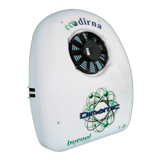
Manuels Connexes pour dirna Bergstrom bycool green line DINAMIC 1.1 SCANIA


Sommaire des Matières pour dirna Bergstrom bycool green line DINAMIC 1.1 SCANIA
-
Page 34: Recommendations Pour Le Montage
Guide de l’utilisateur 220.AA1.1032 en air conditionné sur véhicules. Solution des problèmes 220.AA1.1031 dirna Bergstrom, s.l. ne sera pas responsable des Garantie 220.AA1.0017 dommages ou des bris dérivés d’une installation ou d’une manipulation incorrecte ni des modifications réalisées sans autorisation expresse par écrit. - Page 35 DINAMIC 1.1 Air conditioning for vehicles OPERATIONS PREVUES: • Démonter batterie. • Démonter le panneau intérieur de distribution d’air de l’unité d’évaporation. PAR L’INTERIEUR DE LA CABINE: Présenter le modèle fourni et marquer les perçages. 60 mm Ø48 Ø35 Ø19 Procéder au perçage Ø4 en traversée avec une broche longue en position de perçage ARRIBA...
- Page 36 DINAMIC 1.1 Air conditioning for vehicles PAR L’EXTERIEUR DE LA CABINE: Présenter modèle au niveau par l’extérieur, en prenant pour référence le perçage effectué Ø4 et marquer et effectuer les perçages restant. Attention : le trou de Ø 35 du modèle n’est pas réalisé.
- Page 37 DINAMIC 1.1 Air conditioning for vehicles Placer les bouchons d’écrous et traversées. Passer le tuyau d’évacuation par le perçage Ø19, la traversée vers l’intérieur de la cabine. Sur les goujons, serrer (4) écrous M6 avec Tapisserie Tôle camion EXTÉRIEUR INTÉRIEUR (4) rondelles planes Ø...
- Page 38 DINAMIC 1.1 Air conditioning for vehicles Passer le tuyau d’évacuation par le perçage de la base de l’évaporateur et connecter le bac. Passer les câblages vers l’extérieur à travers le trou Ø 35 de la tapisserie et à travers le trou Ø...
-
Page 39: Très Important
DINAMIC 1.1 Air conditioning for vehicles Placer le protecteur en aluminium avec des écrous et serrer. Introduire la base évaporateur sur goujons et fixer avec (4) rondelles planes (4) grower et (4) écrous M6. TRÈS IMPORTANT Tapisserie Support L’écoulement doit présenter une chute évaporateur suffisante pour éviter que l’eau atteigne la tapisserie. - Page 40 DINAMIC 1.1 Air conditioning for vehicles Connecter le capteur d’air de retour et le câble de communication au contrôle électronique. Fixer à nouveau le panneau intérieur de distribution d’air avec des vis, en utilisant un tournevis aimanté et placer des bouchons.
-
Page 41: Montage Du Condensateur
DINAMIC 1.1 Air conditioning for vehicles MONTAGE DU CONDENSATEUR: Dans le véhicule, démonter le couvercle et lâcher le câblage du ventilateur du condenseur. Présenter le modèle et marquer les trous. Attention : sur certains modèles, il existe une grille de sortie d’air sur le côté gauche (voir étape 5). - Page 42 DINAMIC 1.1 Air conditioning for vehicles Faire d’abord les (2) perçages inférieurs de Ø 9 et placer ensuite (2) écrous rivet M6 et goujons filetés M6. Présenter l’unité et marquer le reste des trous, sauf lorsqu’elle coïncide avec la grille de sortie d’air.
- Page 43 DINAMIC 1.1 Air conditioning for vehicles grille sortie d’air Pour libérer la grille de sortie d’air, fixer l’unité avec (7) vis 6/100x45, une rondelle grower et séparateur 25mm plate. (*) À travers la partie arrière, fixer (2) séparateurs de 25 mm dans la zone supérieure et sur le reste, placer un séparateur de 10 mm.
- Page 44 DINAMIC 1.1 Air conditioning for vehicles Connecter le câblage et les raccords sur l’évaporateur et sceller avec ruban anti- égouttement. Connecter le câblage d’alimentation. Présenter le protecteur de tuyaux avec le joint, marquer et percer à Ø 4. Peindre avec le produit anticorrosion fourni et fixer avec des vis taraudeuses de 4,8x19mm.
- Page 45 DINAMIC 1.1 Air conditioning for vehicles Coller les supports en plastique, brides de fixation et fixer la tuyauterie, les câblages et le tuyau d’évacuation (nettoyer zone de montage). Placer vanne de drainage. IMPORTANT: Le tuyau d’écoulement ne doit présenter aucun étranglement et il doit avoir une inclinaison suffisante pour permettre une évacuation correcte de l’eau de condensation.
- Page 46 DINAMIC 1.1 Air conditioning for vehicles Rabattre la cabine et passer le câblage selon les indications vers la boîte de connexions, en le fixant avec des anneaux de serrage ou des brides. Connecter le câblage à la boîte de connexions.
-
Page 47: Générale De L'unité
DINAMIC 1.1 Air conditioning for vehicles VUE GENERALE DE L’UNITÉ DE CONDENSATION ET TUYAUTERIE. GÉNÉRALE L’UNITÉ ÉVAPORATRICE. -
Page 48: Schéma Électrique
DINAMIC 1.1 Air conditioning for vehicles Schéma Électrique AVIS IMPORTANT Attention de ne pas inverser les polarités au moment de connecter l’alimentation à l’équipement. Si cela se produisait, la plaque de commande ne s’allumerait pas et l’équipement ne fonctionnerait pas. Capteur d’air de retour Souffleur... - Page 84 Dirna Bergstrom behält sich vor, aus technischen oder kaufmännischen Gründen jederzeit Änderungen HIWEIS: der Angaben dieser Veröffentlichung vorzunehmen. Dirna Bergstrom si riserva il diritto di effettuare modifiche in qualsiasi momento ai dati contenuti in questa ATTENZIONE: pubblicazione, per motivi tecnici o commerciali.