
Manuels Connexes pour Wilo Para Série


Sommaire des Matières pour Wilo Para Série
- Page 1 Pioneering for You Wilo-Para de Einbau- und Betriebsanleitung en Installation and operating instructions fr Notice de montage et de mise en service 4 533 597-Ed.01 / 2020-02...
- Page 2 Fig. 1: Para.../SC Para.../iPWM Para.../LIN...
- Page 3 Fig. 2: Fig. 4: Fig. 5a: Fig. 3: Fig. 5b: PE N...
- Page 4 Fig. 5c: Fig. 5f: Fig. 5d: Fig. 6: Fig. 5e:...
- Page 5 Einbau- und Betriebsanleitung Installation and operating instructions Notice de montage et de mise en service...
-
Page 7: Über Diese Anleitung
Sach- und Personenschäden verwen- det und unterschiedlich dargestellt: • Sicherheitshinweise für Personenschäden beginnen mit einem Signalwort und haben ein entsprechendes Symbol vorangestellt. • Sicherheitshinweise für Sachschäden beginnen mit einem Signalwort und werden ohne Symbol dargestellt. Einbau- und Betriebsanleitung Wilo-Para... - Page 8 Das Personal muss die folgenden Qualifikationen haben: • Elektrische Arbeiten müssen von einer Elektrofach- kraft (nach EN 50110-1) durchgeführt werden. • Montage/Demontage muss von einer Fachkraft durchgeführt werden, die im Umgang mit den not- wendigen Werkzeugen und erforderlichen Befesti- gungsmaterialien ausgebildet ist. Wilo SE 02/2020...
-
Page 9: Elektrische Arbeiten
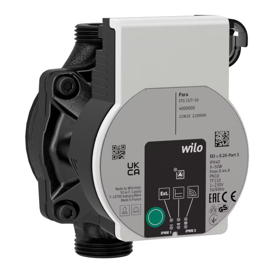
Gebrauchs des Geräts unter- wiesen wurden und sie die daraus resultierenden Gefahren verstehen. Kinder dürfen nicht mit dem Gerät spielen. Rei- nigung und Benutzerwartung dürfen nicht von Kindern ohne Beaufsichtigung durchgeführt werden. Einbau- und Betriebsanleitung Wilo-Para... - Page 10 3 Produktbeschreibung und Funktion Übersicht Wilo-Para (Fig. 1) 1 Pumpengehäuse mit Verschraubungsanschlüssen 2 Nassläufermotor 3 Kondensatablauföffnungen (4x am Umfang) 4 Gehäuseschrauben 5 Regelmodul 6 Typenschild 7 Bedientaste zur Einstellung der Pumpe 8 Betriebs-/Störmelde LED 9 Anzeige der ausgewählten Regelungsart 10 Anzeige der ausgewählten Kennlinie (I, II, III)
- Page 11 • LED leuchtet/blinkt bei Störung (siehe Kapitel 10.1) • Anzeige der gewählten Regelungsart Δp-v, Δp-c und Konstant-Drehzahl • Anzeige der gewählten Kennlinie (I, II, III) innerhalb der Regelungsart • Anzeigekombinationen der LEDs während der Entlüf- tungsfunktion, manuellem Neustart und Tastensperre Einbau- und Betriebsanleitung Wilo-Para...
- Page 12 (I, II, III) Anwendungen ohne veränderliche Rohrnetzkennlinie (z. B. Speicherladepumpen), sowie Einrohr-Heizungssy- steme mit Heizkörpern. Die Regelung hält die eingestellte Förderhöhe unabhän- gig vom geförderten Volumenstrom kontant. Drei vordefinierte Kennlinien (I, II, III) zur Auswahl. Q/m³/ h Wilo SE 02/2020...
- Page 13 < 5: Pumpe läuft bei maximaler Drehzahl 5-85: Die Drehzahl der Pumpe sinkt linear von n nach n 85-93: Pumpe läuft bei minimaler Drehzahl (Betrieb) 85-88: Pumpe läuft bei minimaler Drehzahl (Anlauf) 93-100: Pumpe stoppt (Bereitschaft) Einbau- und Betriebsanleitung Wilo-Para...
- Page 14 Einstellungen an der Pumpe. Sie schützt vor ungewollter oder unberechtigter Verstellung der Pumpe. Werkseinstellung Die Werkseinstellung wird durch Drücken und Halten aktivieren der Bedientaste bei gleichzeitigem Ausschalten der Pumpe aktiviert. Bei erneutem Einschalten läuft die Pumpe in Werkseinstellung (Auslieferungszustand). Wilo SE 02/2020...
-
Page 15: Bestimmungsgemäße Verwendung
4 Bestimmungsgemäße Verwendung Hocheffizienz-Umwälzpumpen der Baureihe Wilo-Para dienen ausschließlich zum Umwälzen von Medien in Warmwasser-Heizungsanlagen und ähnlichen Systemen mit ständig wechselnden Förderströmen. Zugelassene Medien: • Heizungswasser nach VDI 2035 (CH: SWKI BT 102-01). • Wasser-Glykolmischungen* mit maximal 50 % Glyko- lanteil. -
Page 16: Transport Und Lagerung
Einbau ausschließlich durch qualifizierten Fachhand- werker. WARNUNG! Verbrennungsgefahr durch heiße Oberflächen! Pumpengehäuse (1) und Nassläufermotor (2) können heiß werden und bei Berührung zu Verbrennung führen. • Im Betrieb nur das Regelmodul (5) berühren. • Pumpe vor allen Arbeiten abkühlen lassen. Wilo SE 02/2020... - Page 17 • Einbauort entsprechend der zulässigen Einbaulage (Fig. 2) auswählen. • Der Motor muss immer waagerecht verbaut sein. • Der elektrische Anschluss darf nie nach oben zeigen. • Vor und hinter der Pumpe Absperrarmaturen ein- bauen, um Pumpenaustausch zu erleichtern. Einbau- und Betriebsanleitung Wilo-Para...
- Page 18 • Pumpe mit einem Maulschlüssel gegen verdrehen sichern und mit den Rohrleitungen dicht verschrau- ben. • Gegebenenfalls Wärmedämmschale wieder anbringen. VORSICHT! Mangelnde Wärmeabfuhr und Kondenswasser können Regelmodul und Nassläufermotor beschädigen. • Nassläufermotor (2) nicht wärmedämmen. • Alle Kondensatablauföffnungen (3) frei lassen. Wilo SE 02/2020...
-
Page 19: Elektrischer Anschluss
• Bei Anwendungen, bei denen nicht klar ist, ob die Pumpe mit getakteter Spannung betrieben wird, vom Regelungs-/Anlagenhersteller bestätigen las- sen, dass die Pumpe mit sinusförmiger Wechsel- spannung betrieben wird. • Ein-/Ausschaltung der Pumpe über Triacs/Halblei- terrelais im Einzelfall prüfen. Einbau- und Betriebsanleitung Wilo-Para... - Page 20 Netzanschlusskabel montieren (Fig. 3): Netzkabel 1. Standard: 3-adriges umspritztes Kabel mit Messing Aderendhülsen 2. Optional: Netzkabel mit 3-poligem Anschlussstecker 3. Optional: Wilo-Connectorkabel (Fig. 3, Pos. b) • Kabelbelegung: 1 gelb/grün: PE ( 2 blau: N 3 braun: L • Arretierungsknopf des 3-poligen Pumpensteckers herunterdrücken und den Stecker am...
- Page 21 Wilo-Connector montieren Wilo-Connector • Anschlussleitung von der Spannungsversorgung trennen. • Klemmenbelegung ( (PE), N, L ) beachten. • Wilo-Connector anschließen und montieren (Fig. 5a bis 5e). Pumpe anschließen • Pumpe erden. • Wilo-Connector am Anschlusskabel anschließen, bis er einrastet (Fig. 5f).
- Page 22 3 schwarz: LIN-Busdaten • Signaleigenschaften: - Busgeschwindigkeit: 19200 bit/s VORSICHT! Der Anschluss von Netzspannung (230 V AC) an die Kom- munikationspins (iPWM/LIN) zerstört das Produkt. • Am PWM Eingang beträgt die maximale Spannungshöhe 24 V getaktete Eingangsspannung. Wilo SE 02/2020...
-
Page 23: Regelungsart Einstellen
Kennlinien erfolgt im Uhrzeigersinn. • Bedientaste kurz (ca. 1 Sekunde) drücken. LEDs zeigen die jeweils eingestellte Regelungsart und Kennlinie an. Die Darstellung der möglichen Einstellungen im Folgen- den (zum Beispiel: Konstant-Drehzahl / Kennlinie III): Einbau- und Betriebsanleitung Wilo-Para... - Page 24 Regelungsart Kennlinie Konstant-Drehzahl Konstant-Drehzahl Differenzdruck variabel Δp-v Differenzdruck variabel Δp-v Differenzdruck variabel Δp-v Differenzdruck konstant Δp-c Differenzdruck konstant Δp-c Differenzdruck konstant Δp-c Konstant-Drehzahl • Mit dem 9. Tastendruck ist die Grundeinstellung (Konstant-Drehzahl / Kennlinie III) wieder erreicht. Wilo SE 02/2020...
- Page 25 Bei erneutem Einschalten läuft die Pumpe in Werksein- stellung (Auslieferungszustand). 8 Außerbetriebnahme Pumpe stillsetzen Im Falle von Beschädigungen an der Anschlussleitung oder anderen elektrischen Komponenten Pumpe umge- hend stillsetzen. • Pumpe von der Spannungsversorgung trennen. • Wilo-Kundendienst oder Fachhandwerker kontaktieren. Einbau- und Betriebsanleitung Wilo-Para...
-
Page 26: Störungen, Ursachen Und Beseitigung
• Die Störmelde-LED zeigt eine Störung an. • Die Pumpe schaltet ab (in Abhängigkeit von der Stö- rung), versucht zyklische Neustarts. Störungen Ursachen Beseitigung Blockierung Rotor blockiert Manuellen Neustart leuchtet aktivieren oder Kontaktierung/ Wicklung defekt Kundendienst Wicklung anfordern Wilo SE 02/2020... - Page 27 Die LEDs blinken nacheinander im Uhrzeigersinn. • Zum Abbrechen die Bedientaste 5 Sekunden drücken. HINWEIS Nach erfolgtem Neustart zeigt die LED-Anzeige die zuvor eingestellten Werte der Pumpe. Lässt sich eine Störung nicht beheben, Fachhandwer- ker oder Wilo-Kundendienst kontaktieren. Einbau- und Betriebsanleitung Wilo-Para...
-
Page 28: Entsorgung
Sammelstellen abgeben. • Örtlich geltende Vorschriften beachten! Informationen zur ordnungsgemäßen Entsorgung bei der örtlichen Gemeinde, der nächsten Abfallentsor- gungsstelle oder bei dem Händler erfragen, bei dem das Produkt gekauft wurde. Weitere Informationen zum Recycling unter www.wilo-recycling.com Wilo SE 02/2020... -
Page 29: About These Instructions
• Safety instructions relating to personal injury start with a signal word and are preceded by a corre- sponding symbol. Installation and operating instructions Wilo-Para... - Page 30 • Be instructed about locally applicable regulations governing accident prevention. • Have read and understood the installation and oper- ating instructions. Personnel must have the following qualifications. • Electrical work must be carried out by an authorised electrician (in accordance with EN 50110-1). Wilo SE 02/2020...
-
Page 31: Electrical Work
Children are not allowed to play with the device. Cleaning and user maintenance must not be carried out by children without supervision. Installation and operating instructions Wilo-Para... - Page 32 3 Product description and function Overview Wilo-Para (Fig. 1) 1 Pump housing with screwed connections 2 Glandless motor 3 Condensate drain openings (4x around circumference) 4 Housing screws 5 Control module 6 Rating plate 7 Operating button for pump adjustment...
- Page 33 • Display of selected control mode Δp-v, Δp-c and constant speed • Display of selected pump curve (I, II, III) within the control mode • LED indicator combinations during the pump venting function, manual restart and key lock Installation and operating instructions Wilo-Para...
- Page 34 Δp-c (I, II, III) heating systems with radiators. The control keeps the set delivery head constant irre- spective of the pumped volume flow. There are three pre-defined pump curves (I, II, III) to choose from. Q/m³/ h Wilo SE 02/2020...
-
Page 35: External Control
Pump runs at maximum speed 5-85: The speed of the pump decreases linearly from n to n 85-93: Pump runs at minimum speed (operation) 85-88: Pump runs at minimum speed (starting) 93-100: Pump stops (standby) Installation and operating instructions Wilo-Para... - Page 36 Activating The factory setting is activated by pressing and holding factory setting the operating button whilst switching off the pump. When the pump is switched on again, the pump runs using the factory settings (delivery condition). Wilo SE 02/2020...
-
Page 37: Intended Use
4 Intended use High-efficiency circulators in the Wilo-Para series are exclusively intended for circulating fluids in hot-water heating systems and similar systems with constantly changing volume flows. Permitted fluids: • Heating water according to VDI 2035 (CH: SWKI BT 102-01). -
Page 38: Transportation And Storage
Risk of burns from hot surfaces! Pump housing (1) and glandless motor (2) may become hot and cause burns if touched. • During operation, only touch the control module (5). • Allow the pump to cool down before commencing any work. Wilo SE 02/2020... -
Page 39: Preparation
(Fig. 2). • The motor must always be installed horizontally. • The electrical connection must never face upwards. • Install shut-off devices upstream and downstream of the pump to facilitate pump replacement. Installation and operating instructions Wilo-Para... - Page 40 • Re-mount the thermal insulation shell if required. CAUTION! Insufficient heat dissipation and condensation water may damage the control module and the glandless motor. • Do not thermally insulate the glandless motor (2). • Ensure all condensate drain openings (3) are kept free. Wilo SE 02/2020...
-
Page 41: Electrical Connection
AC voltage. • Switching the pump on/off via triacs/solid-state relays must be examined on a case-by-case basis. Installation and operating instructions Wilo-Para... -
Page 42: Mains Cable Connection
Installing the mains connection cable (Fig. 3): connection 1. Standard: 3-core coated cable with brass ferrules 2. Optional: Mains cable with 3-pin connection plug 3. Optional: Wilo-Connector cable (Fig. 3, item b) • Cable assignment: 1 yellow/green: PE ( 2 blue: N 3 brown: L •... - Page 43 • Connect and install the Wilo-Connector (Fig. 5a to 5e). Connecting the pump • Earth the pump. • Connect the Wilo-Connector to the connection cable until it snaps into place (Fig. 5f). Removing the Wilo-Connector • Disconnect the connecting cable from the power supply.
- Page 44 - Bus speed: 19200 bit/s CAUTION! The connection of mains voltage (230 V AC) to the com- munication pins (iPWM/LIN) will destroy the product. • At the PWM input, the maximum voltage is 24 V pulsed input voltage. Wilo SE 02/2020...
-
Page 45: Setting The Control Mode
• Press the operating button briefly (approx. 1 second). LEDs display the set control mode and pump curve. The following shows the various possible settings (for example: constant speed / characteristic curve III): Installation and operating instructions Wilo-Para... - Page 46 Variable differential pressure Δp-v Constant differential pressure Δp-c Constant differential pressure Δp-c Constant differential pressure Δp-c Constant speed • Pressing the button for the 9th time returns to the basic setting (constant speed / characteristic curve III). Wilo SE 02/2020...
- Page 47 • Disconnect the pump from the power supply. • Contact Wilo customer service or a specialist technician. 9 Maintenance Cleaning • Carefully remove dirt from the pump on a regular basis using a dry duster.
-
Page 48: Faults, Causes And Remedies
Winding defective up red customer service winding Under/overvoltage Power supply too low/high on mains Check mains side voltage and Flashes Excessive Module interior too operating module warm conditions, and temperature request customer service Short-circuit Motor current too high Wilo SE 02/2020... - Page 49 • To cancel, press and hold the operating button for 5 seconds. NOTICE After the restart, the LED display shows the previously set values of the pump. If the fault cannot be remedied, contact a specialist technician or Wilo customer service. Installation and operating instructions Wilo-Para...
- Page 50 • Observe the locally applicable regulations! Please consult your local municipality, the nearest waste disposal site, or the dealer who sold the product to you for information on proper disposal. Further recycling information at www.wilo-recycling.com Wilo SE 02/2020...
-
Page 51: Généralités
• Dangers pour les personnes par influences élec- triques, mécaniques ou bactériologiques ainsi que par des champs électromagnétiques • Dangers pour l'environnement par fuite de matières dangereuses • Dommages matériels • Défaillances de fonctions importantes du produit Notice de montage et de mise en service Wilo-Para... -
Page 52: Signalisation De Consignes De Sécurité
Remarque utile sur le maniement du produit. Symboles Les symboles suivants sont utilisés dans cette notice : Dangers dus à la tension électrique Symbole général de danger Mise en garde contre les surfaces/fluides chauds Mise en garde contre les champs magnétiques Avis Wilo SE 02/2020... -
Page 53: Travaux Électriques
• Le produit doit être mis à la terre. • Faire remplacer immédiatement des câbles défec- tueux par un électricien professionnel. • Ne jamais ouvrir le module de régulation et ne jamais retirer des éléments de commande. Notice de montage et de mise en service Wilo-Para... -
Page 54: Obligations De L'opérateur
Les opérations de nettoyage et d'entretien ne doivent pas être réalisées par des enfants sans surveillance. 3 Description du produit et fonctionnement Aperçu Wilo-Para (Fig. 1) 1 Corps de pompe avec raccords filetés 2 Moteur à rotor noyé 3 Circuits d'évacuation des condensats (4x sur la circonférence) -
Page 55: Fonctionnement
Température ambiante +25 °C 0 °C à +70 °C Pression de service max. 10 bar (1000 kPa) Pression d'entrée minimale 0,5 bar / 1,0 bar (50 kPa / 100 kPa) à +95 °C/+110 °C Notice de montage et de mise en service Wilo-Para... -
Page 56: Témoins Lumineux (Led)
• Sélectionner la courbe caractéristique (I, II, III) dans le mode de régulation Maintenir la touche enfoncée • Activer la fonction de purge (appuyer pendant 3 secondes) • Activer le redémarrage manuel (appuyer pendant 5 secondes) • Verrouiller/déverrouiller les touches (appuyer pendant 8 secondes) Wilo SE 02/2020... -
Page 57: Modes De Régulation Et Fonctions
La pompe fonctionne dans trois vitesses fixes prescrites (I, II, III). AVIS Réglage d'usine : Vitesse de rotation constante, courbe caracté- ristique III Q/m³/ h Notice de montage et de mise en service Wilo-Para... -
Page 58: Régulation Externe Via Un Signal Ipwm
Comportement en cas de rupture de câble : Si le câble de signal est séparé de la pompe, p. ex. par une 7 12 15 95 100 rupture de câble, la pompe s'arrête. Entrée de signal PWM [%] 0-7 : La pompe s'arrête (disponibilité) Wilo SE 02/2020... -
Page 59: Redémarrage Manuel
Les circulateurs à haut rendement de la gamme Wilo-Para servent uniquement à faire circuler des fluides dans des installations de chauffage à eau chaude et des systèmes analogues présentant des débits toujours changeants. Fluides autorisés : Notice de montage et de mise en service Wilo-Para... -
Page 60: Utilisation Non Conforme
• Ne jamais faire effectuer des travaux non autorisés. • Ne jamais utiliser la pompe hors des limites d'utilisa- tion indiquées. • Ne jamais effectuer de modifications arbitraires. • Utiliser exclusivement les accessoires autorisés. • Ne jamais utiliser la pompe avec une commande par coupe. Wilo SE 02/2020... -
Page 61: Transport Et Stockage
• Ne toucher que le module de régulation (5) lors du fonctionnement. • Laisser refroidir la pompe avant d'effectuer un travail quelconque. Notice de montage et de mise en service Wilo-Para... -
Page 62: Préparation Installation À L'intérieur D'un Bâtiment
• La température du fluide et la température ambiante ne doivent jamais dépasser les températures limites inférieures et supérieures prescrites. • Choisir autant que possible un site de montage bien accessible. • Respecter la position de montage autorisée (Fig. 2) de la pompe. Wilo SE 02/2020... - Page 63 (EN 12828). • Achever toutes les opérations de soudage et de bra- sage. • Rincer le système de tuyauterie. • Ne pas utiliser la pompe pour rincer le système de tuyauterie. Notice de montage et de mise en service Wilo-Para...
-
Page 64: Raccordement Électrique
Risque de blessures mortelles pour les personnes por- tant des implants médicaux dû aux aimants perma- nents intégrés dans la pompe. • Ne jamais démonter le moteur. Raccordement électrique Le raccordement électrique doit être effectué par un électricien professionnel. Wilo SE 02/2020... - Page 65 • Ne faire fonctionner la pompe que sur une tension alternative sinusoïdale. • Tenir compte du nombre de démarrages : - Mises en marche/arrêts par la tension d'alimentation ≤ 100/24 h. Notice de montage et de mise en service Wilo-Para...
-
Page 66: Raccordement Du Wilo-Connector
2. En option : câble électrique avec fiche de raccorde- ment 3 pôles 3. En option : câble Wilo-Connector (Fig. 3, pos. b) • Affectation des câbles : 1 jaune/vert : PE ( 2 bleu : N 3 marron : L •... -
Page 67: Raccordement
7,5 mA, absorbée par l'interface de la pompe. - Polarité du signal : oui LIN : • Affectation des câbles : 1 marron : 12 V CC à 24 V CC (+/-10 %) Notice de montage et de mise en service Wilo-Para... -
Page 68: Mise En Service
Les rangées de LED supérieures et inférieures cli- gnotent en alternance à intervalle d'1 seconde. • Pour annuler, appuyer pendant 3 secondes sur la touche de commande. AVIS Après la purge, l'affichage LED affiche les valeurs préalablement réglées de la pompe. Wilo SE 02/2020... -
Page 69: Paramétrer Le Mode De Régulation
Affichage LED Mode de régulation Courbe caractéristique Vitesse de rotation constante Vitesse de rotation constante Pression différentielle variable Δp-v Pression différentielle variable Δp-v Pression différentielle variable Δp-v Pression différentielle constante Δp-c Notice de montage et de mise en service Wilo-Para... - Page 70 être modifiés. • La désactivation du verrouillage des touches s'effec- tue de la même façon que l'activation. AVIS Tous les réglages et affichages sont conservés en cas de coupure de l'alimentation électrique. Wilo SE 02/2020...
-
Page 71: Mise Hors Service
Arrêter immédiatement la pompe dans le cas de détério- rations sur les câbles de raccordement ou d'autres com- posants électriques. • Couper la pompe de l'alimentation électrique. • Contacter le service après-vente Wilo ou un artisan spé- cialisé. 9 Entretien Nettoyage •... -
Page 72: Rapports De Défauts
Alimentation élec- surtension trique côté réseau trop Contrôler la tension faible/élevée d'alimentation et Clignote en Température Intérieur du module les conditions rouge excessive du trop chaud d'utilisation, module contacter le service après-vente Court-circuit Intensité moteur trop élevée Wilo SE 02/2020... - Page 73 Une fois le redémarrage effectué, l'affichage LED montre les valeurs de la pompe préalablement réglées. S'il est impossible de supprimer une panne, contacter un artisan spécialisé ou le service après-vente Wilo. Notice de montage et de mise en service Wilo-Para...
-
Page 74: Élimination
Pour des informations sur l'élimination correcte, s'adres- ser à la municipalité locale, au centre de traitement des déchets le plus proche ou au revendeur auprès duquel le produit a été acheté. Pour davantage d'informations sur le recyclage, consulter www.wilo-recycling.com Wilo SE 02/2020... - Page 75 EN 61000-6-1:2007 EN IEC 63000 EN 61000-6-2:2005 EN 61000-6-3:2007+A1:2011 EN 61000-6-4:2007+A1:2011 Digital unterschrieben von Holger Herchenhein Dortmund, Datum: 2019.05.22 08:10:19 +02'00' H. HERCHENHEIN WILO SE Senior Vice President - Group Quality Nortkirchenstra e 100 44263 Dortmund - Germany N°4224933.03 (CE-A-S n°4530300)
- Page 76 EN 61000-6-1:2007 EN IEC 63000 EN 61000-6-2:2005 EN 61000-6-3:2007+A1:2011 Digital EN 61000-6-4:2007+A1:2011 unterschrieben von Holger Herchenhein Dortmund, Datum: 2019.07.15 08:57:44 +02'00' H. HERCHENHEIN WILO SE Senior Vice President - Group Quality Nortkirchenstra e 100 44263 Dortmund - Germany N°4227670.03 (CE-A-S n°4531129)
- Page 77 EN 61000-6-1:2007 EN IEC 63000 EN 61000-6-2:2005 EN 61000-6-3:2007+A1:2011 EN 61000-6-4:2007+A1:2011 Digital unterschrieben von Holger Herchenhein Dortmund, Datum: 2019.07.15 09:44:38 +02'00' H. HERCHENHEIN WILO SE Senior Vice President - Group Quality Nortkirchenstra e 100 44263 Dortmund - Germany N°2209028.01 (CE-A-S n°4532820)
- Page 78 EN 61000-6-1:2007 EN IEC 63000 EN 61000-6-2:2005 EN 61000-6-3:2007+A1:2011 EN 61000-6-4:2007+A1:2011 Digital unterschrieben von Holger Herchenhein Dortmund, Datum: 2019.07.15 08:57:10 +02'00' H. HERCHENHEIN WILO SE Senior Vice President - Group Quality Nortkirchenstra e 100 44263 Dortmund - Germany N°2195354.02 (CE-A-S n°4530656)
- Page 79 AE/EC DEARBHÚ COMHLÍONTA WILO SE vakuuttaa, että tässä vakuutuksessa kuvatut tuotteet ovat WILO SE ndearbhaíonn an cur síos ar na táirgí atá i ráiteas seo, siad i seuraavien eurooppalaisten direktiivien määräysten sekä niihin gcomhréir leis na forálacha atá sna treoracha seo a leanas na hEorpa agus sovellettavien kansallisten lakiasetusten mukaisia: leis na dlíthe náisiúnta is infheidhme orthu:...
- Page 80 EU/ES-IZJAVA O SKLADNOSTI WILO SE estne prehlasuje, že výrobky ktoré sú predmetom tejto WILO SE izjavlja, da so izdelki, navedeni v tej izjavi, v skladu z dolo ili deklarácie, sú v súlade s požiadavkami nasledujúcich európskych direktív a naslednjih evropskih direktiv in z nacionalnimi zakonodajami, ki jih odpovedajúcich národných legislatívnych predpisov:...
- Page 82 WILO SE Nortkirchenstraße 100 D-44263 Dortmund Germany T +49(0)231 4102-0 F +49(0)231 4102-7363 wilo@wilo.com Pioneering for You www.wilo.com...