Table des Matières
Publicité
Les langues disponibles
Les langues disponibles
Liens rapides
Publicité
Chapitres
Table des Matières

Manuels Connexes pour schmalz X-Pump SXP

Sommaire des Matières pour schmalz X-Pump SXP
- Page 1 Innovative Vakuum-Automatisierung Kurz-Betriebsanleitung Schmalz X-Pump SXP/SXMP Brief Operating Instructions Notice d'utilisation Instrucciones de servicio resumidas Istruzioni per l'uso in breve...
-
Page 2: Table Des Matières
Schmalz X-Pump Kurzanleitung NHALTSVERZEICHNIS Beschreibung ..................1-3 Basismodul ......................1-3 Erweiterungsmodule ....................1-4 Inbetriebnahme ......................1-5 Elektrischer Anschluss .................... 1-5 Basis-Einstellungen ................2-6 Bedien- und Anzeigeelemente ................2-6 Bedienelemente ...................... 2-7 Grundmenü ........................ 2-8 Einstellung der Schwellwerte [H-1], [h-1], [H-2], [h-2] ..........2-9 Nullpunkteinstellung (Kalibrierung) [CAL] ............... -
Page 3: Beschreibung
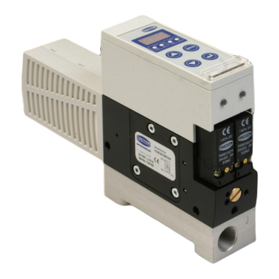
Schmalz X-Pump Kurzanleitung ESCHREIBUNG Basismodul Das Basismodul des Ejektors ist wie folgt aufgebaut: Position Beschreibung Bedien- und Anzeigeelement Diagnoseanzeige Anzeige Ventilzustand Pilotventil „Abblasen“ – NC...stromlos geschlossen Pilotventil „Saugen“ – NO oder NC je nach Ejektorvariante Drosselschraube für Abblasvolumenstrom Vakuumanschluss G3/8“ (Kennzeichnung 2[V]) -
Page 4: Erweiterungsmodule
Schmalz X-Pump Kurzanleitung Erweiterungsmodule Das Basismodul lässt sich um eine Vielzahl von Erweiterungsmodulen ergän- zen und modifizieren: Position Beschreibung Basismodul – Saugventil NO...stromlos offen Basismodul – Saugventil NC...stromlos geschlossen Basismodul – Saugventil IMP...bistabil über Impuls Power-Abblasmodul SXMP Horizontaler Pneumatikanschluss (1[P]= G3/8“, 2[V]= G3/8“) Vertikaler Pneumatikanschluss (1[P]= G1/4“, 2[V]= G3/8“) -
Page 5: Inbetriebnahme
Signalausgang „Diagnose“ Signalausgang „DAF2“ grau OUT3 bei Verwendung Schmalz-Anschlussleitung Art.-Nr. 21.04.05.00079 bei Verwendung Schmalz-Anschlussleitung Art.-Nr. 21.04.05.00080 Analysefunktion DAF: siehe Kapitel Diagnose-Analysefunktion (DAF) NO-Version: Saugen AUS, NC-Version: Saugen EIN, IMP-Version: nur Saugen EIN NO/NC-Version: Abblasen EIN/AUS, IMP-Version: Saugen AUS und Abblasen EIN/AUS... -
Page 6: Basis-Einstellungen
Schmalz X-Pump Kurzanleitung M12-S TECKERANORDNUNG TECKER POLIG Betrieb des Systems ausschließlich über Netzgeräte mit Schutzkleinspannung (PELV) und sicherer elektrischer Trennung der Betriebsspannung, gemäß EN60204. Vorsicht Vorsicht ASIS INSTELLUNGEN Bedien- und Anzeigeelemente Über die Folientastatur mit dreistelligem Display sowie 4 zusätzlichen Leuchtdi- oden ist eine sehr einfache Einstellung und Bedienung des Ejektors gewährleis-... -
Page 7: Bedienelemente
Schmalz X-Pump Kurzanleitung Bedienelemente Im Grundzustand (Anzeigemodus) wird stets das aktuelle Systemvakuum an- gezeigt. In diesem Zustand haben die Tasten folgende Bedeutung: Die Bedienstruktur gliedert sich in Einstellungen des Grundmenüs und des Konfigurationsmenüs. Für Standardanwendungen ist die Einstellung des Ejek- tors im Grundmenü... -
Page 8: Grundmenü
Schmalz X-Pump Kurzanleitung RUNDMENÜ Über das Grundmenü können alle wichtigen Einstellungen für Standardanwen- dungen des Ejektors vorgenommen und abgelesen werden. Einstellung Einstellung Wert blinkt zur Wert blinkt zur des Wertes des Wertes Bestätigung Bestätigung weiter bei weiter bei blinken blinken... -
Page 9: Einstellung Der Schwellwerte [H-1], [H-1], [H-2], [H-2]
Schmalz X-Pump Kurzanleitung Abschaltwert Luftsparautomatik Einschaltwert Ausgang Teilekontrolle Hysterese Luftsparautomatik Hysterese Ausgang Teilekontrolle H1-h1 Einschaltwert Luftsparautomatik H2-h2 Ausschaltwert Ausgang Teilekontrolle Einstellung der Schwellwerte [H-1], [h-1], [H-2], [h-2] Die Reihenfolge der Parameter im Menü ist der Übersicht zu entnehmen. Taste <MENU> drücken ... -
Page 10: Nullpunkteinstellung (Kalibrierung) [Cal]
Schmalz X-Pump Kurzanleitung Nullpunkteinstellung (Kalibrierung) [CAL] Zur Nullpunkteinstellung muss der Vakuumkreis des Systems entlüftet sein (zur Atmosphäre). Taste <MENU> drücken Gültigen PIN eingeben falls Menü verriegelt Taste <UP> oder <DOWN> so oft drücken, bis [CAL] in der Anzeige erscheint ... -
Page 11: Pin-Code Für Grundmenü [Pn1]
Schmalz X-Pump Kurzanleitung PIN-Code für Grundmenü [Pn1] Um den Zugang zum Grundmenü zu sperren kann dieses mit dem PIN-Code [Pn1] verriegelt werden. Unabhängig vom Grundmenü kann auch das erweiterte Konfigurationsmenü verriegelt werden! Im Auslieferungszustand ist der PIN-Code 000, das Grundmenü ist somit nicht gesperrt. -
Page 12: Interne Zyklen-Zähler [Ct1], [Ct2], [Ct3]
Schmalz X-Pump Kurzanleitung Interne Zyklen-Zähler [ct1], [ct2], [ct3] Das Ejektorsystem verfügt über verschiedene interne Zähler. Zähler 1 wird bei jedem externen Signal auf der Steuerleitung SAUGEN erhöht und zählt somit die Saugzyklen. Bei Ejektoren mit Impulsventil wird jeder gültige Saugimpuls gezählt. -
Page 13: Interne Zyklen-Zähler Anzeigen
Schmalz X-Pump Kurzanleitung Interne Zyklen-Zähler anzeigen Taste <MENU> und Taste <UP> >3 Sekunden gedrückt halten Mit den Tasten <UP> oder <DOWN> den gewünschten Zähler wählen Mit der Taste <ENTER> bestätigen Es werden die drei niederwertigsten Stellen des Gesamtzählwertes angezeigt, die rechte LED (out2-h/c) leuchtet. -
Page 14: Leckagesuchfunktion (Lsf)
Schmalz X-Pump Kurzanleitung LeckageSuchFunktion (LSF) > 3 Sekunden Taste <DOWN> und <ENTER> >3 Sekunden gedrückt halten Nachdem die Leckagesuchfunktion aktiviert ist blinken alle LED´s der Ausgän- ge. Im Display wird der aktuelle Vakuumwert angezeigt. Die LeckageSuchFunktion (LSF) wird zum Systemeinfahren und Leckagesu- chen verwendet. - Page 15 Schmalz X-Pump Brief operating instructions ONTENTS Description..................3-16 Basic module ......................3-16 Expansion modules ....................3-17 Putting into service ....................3-18 Electrical connections ....................3-18 Basic Settings..................4-19 Controls and Indicators ................... 4-19 Controls ........................4-20 Basic menu ........................ 4-21 Setting the threshold values [H-1], [h-1], [H-2], [h-2] ..........
-
Page 16: Description
Schmalz X-Pump Brief operating instructions ESCRIPTION Basic module The basic module of the ejector has the following components: Item Description Display and controls Diagnostic indicator Valve-status indicator Pilot valve "Blow off" - NC (normally closed) Pilot valve "Vacuum on" - NO or NC, depending on the ejector variant Throttle screw for blow-off volume flow Vacuum connector G3/8“... -
Page 17: Expansion Modules
Schmalz X-Pump Brief operating instructions Expansion modules The basic module can be expanded and modified with many different expan- sion modules: Item Description Basic module – with suction valve NO... (normally open) Basic module – with suction valve NC... (normally closed) Basic module –... -
Page 18: Putting Into Service
Gray OUT3 Diagnostic signal output "DAF2" signal output When Schmalz connection line item no. 21.04.05.00079 is used When Schmalz connection line item no. 21.04.05.00080 is used DAF analysis function: siehe Kapitel Diagnose-Analysefunktion (DAF) NO-Version: Saugen AUS, NC-Version: Saugen EIN, IMP-Version: nur Saugen EIN... -
Page 19: Basic Settings
Schmalz X-Pump Brief operating instructions ONNECTOR POSITIONS CONNECTORS The system may be operated only with a voltage supplied by a power supply unit which provides a protective low voltage (PELV) and with safe electrical isolation in accordance with EN60204. Caution... -
Page 20: Controls
Schmalz X-Pump Brief operating instructions Controls In the basic state (display mode), the current system vacuum is permanently displayed. In this mode, the keys have the following functions: The operating structure is divided into a basic menu and a configuration menu. -
Page 21: Basic Menu
Schmalz X-Pump Brief operating instructions ASIC MENU The basic menu can be used to make all necessary settings for standard appli- cations of the ejector and to display the current settings. Set the value Set the value Value blinks as... -
Page 22: Setting The Threshold Values [H-1], [H-1], [H-2], [H-2]
Schmalz X-Pump Brief operating instructions Deactivation value for air-saving Activation value of output of part pre- function sent Hysteresis of air-saving function Hysteresis of output of part present Activation value for air-saving Deactivation value of output of part H1-h1 H2-h2... -
Page 23: Setting The Zero Point (Calibration) [Cal]
Schmalz X-Pump Brief operating instructions Setting the zero point (calibration) [CAL] For adjustment of the zero point, the vacuum circuit of the system must be vented (to the atmosphere). Press the <MENU> key. If the menu is locked, enter the appropriate PIN. -
Page 24: Pin For Basic Menu [Pn1]
Schmalz X-Pump Brief operating instructions PIN for basic menu [Pn1] The basic menu can be locked with PIN [Pn1] to prevent unauthorised ac- cess. The extended configuration menu can also be locked, regardless of whether or not the basic menu is locked. -
Page 25: Internal Cycle Counters [Ct1], [Ct2], [Ct3]
Schmalz X-Pump Brief operating instructions Internal cycle counters [ct1], [ct2], [ct3] The ejector system has various internal counters. Counter 1 is incremented with each external signal on the control line SUC- TION and thus counts the suction cycles. In the case of ejectors with pulse valves, each valid suction pulse is counted. -
Page 26: Displaying The Internal Counters
Schmalz X-Pump Brief operating instructions Displaying the internal counters Press and hold <MENU> and <UP> for at least three seconds. Use the <UP> or <DOWN> key to select the desired counter. Press <ENTER> to confirm the selection. -
Page 27: Leak Detection Function (Lsf)
Schmalz X-Pump Brief operating instructions Leak detection function (LSF) > 3 seconds > 3 seconds Press and hold the <DOWN> and <ENTER> keys for at least three seconds. When the leak detection function is active, the LEDs for all outputs blink and the current vacuum value is displayed. - Page 28 Schmalz X-Pump Instructions de service ABLE DES MATIÈRES Description ..................5-29 Module de base ...................... 5-29 Modules d’extension ....................5-30 Mise en service ......................5-31 Connexion électrique ....................5-31 Réglages de base ................6-32 Eléments de commande et d’affichage ..............6-32 Eléments de commande ..................
-
Page 29: Description
Schmalz X-Pump Instructions de service ESCRIPTION Module de base Construction du module de base de l’éjecteur : Position Description Elément de commande et d’affichage Affichage du diagnostic Affichage de l’état des vannes Vanne pilote « évacuation » - NC (NF)… hors tension fermée Vanne pilote «... -
Page 30: Modules D'extension
Schmalz X-Pump Instructions de service Modules d’extension Le module de base peut être complété et modifié à l’aide d’une multitude de modules d’extension : Position Description Module de base – vanne d’aspiration NO... sans courant ouverte Module de base – vanne d’aspiration NC... sans courant fermée Module de base –... -
Page 31: Mise En Service
Sortie de signal « Diagnostic » Sortie de signal « DAF2 » en utilisant le câble Schmalz n° de réf. 21.04.05.00079 en utilisant le câble Schmalz n° de réf. 21.04.05.00080 Fonction d’analyse de diagnostic DAF : voir le chapitre Fonction d’analyse de diagnostic (DAF) Version NO: aspiration ARRET, V. -
Page 32: Réglages De Base
Schmalz X-Pump Instructions de service ISPOSITION CONNECTEURS BROCHES Utilisation du système exclusivement à l’aide de blocs secteur avec très basse tension de protection (TBTP ou PELV) et séparation électrique sécurisée de la tension de service selon EN 60204. Attention Attention EGLAGES DE BASE Eléments de commande et d’affichage... -
Page 33: Eléments De Commande
Schmalz X-Pump Instructions de service Eléments de commande La valeur actuelle du vide du système est affichée en permanence en état initial (mode d’affichage). Dans ce mode, les touches ont les fonctions suivantes : La structure de commande se compose en réglages du menu de base et du menu de configuration. -
Page 34: Menu De Base
Schmalz X-Pump Instructions de service ENU DE BASE Le menu de base permet d’effectuer et de consulter tous les réglages impor- tants pour les applications standard de l’éjecteur. réglage de la réglage de la Valeur clignote Valeur clignote valeur valeur... -
Page 35: Réglage Des Valeurs-Seuils [H-1], [H-1], [H-2], [H-2]
Schmalz X-Pump Instructions de service Valeur de mise hors tension dis- Valeur de mise sous tension sortie con- positif automatique d'économie trôle des pièces d'air Hystérésis dispositif automatique Hystérésis sortie contrôle des pièces d'économie d'air Valeur de mise sous tension... -
Page 36: Réglage Du Point Zero (Calibrage) [Cal]
Schmalz X-Pump Instructions de service Réglage du point zero (calibrage) [CAL] Le circuit de vide du système doit être purgé (vers l’atmosphère) afin de régler le point zéro. Appuyez sur la touche <MENU> Saisissez votre PIN dans le cas où le menu est verrouillé... -
Page 37: Pin Pour Le Menu De Base [Pn1]
Schmalz X-Pump Instructions de service PIN pour le menu de base [Pn1] Le menu de base peut être verrouillé à l’aide d’un PIN [Pn1] afin d’en con- damner l’accès. Le menu de configuration peut également être verrouillé indépendamment du menu de base. -
Page 38: Compteur De Cycles Interne [Ct1], [Ct2], [Ct3]
Schmalz X-Pump Instructions de service Compteur de cycles interne [ct1], [ct2], [ct3] Le système d’éjecteur dispose de différents compteurs internes. Le compteur 1 augmente lors de chaque signal externe de la ligne de com- mande ASPIRATION et compte ainsi les cycles d’aspiration. Toutes les im- pulsion d’aspiration valables sont comptées en présence d’éjecteurs à... -
Page 39: Affichage Du Compteur De Cycles Interne
Schmalz X-Pump Instructions de service Affichage du compteur de cycles interne Maintenez les touches <MENU> et <UP> enfoncées pendant >3 s Sélectionnez le compteur désiré à l’aide des touches <UP> ou <DOWN> Confirmez votre saisie à l’aide de la touche <ENTER>... -
Page 40: Fonction De Recherche De Fuite (Lsf)
Schmalz X-Pump Instructions de service Fonction de recherche de fuite (LSF) > 3 secondes > 3 secondes Maintenez les touches <DOWN> et <ENTER> enfoncées pendant >3 Toutes les DEL des sorties clignotent après avoir activé la fonction recherche de fuite. La valeur actuelle du vide est affichée. - Page 41 Schmalz X-Pump Instrucciones de manejo Í NDICE Descripción ..................7-42 Módulo Básico ......................7-42 Módulos de Ampliación ................... 7-43 Puesta en Servicio ..................... 7-44 Conexión Eléctrica....................7-44 Ajustes Básicos .................. 8-45 Elementos de Manejo y Visualización ..............8-45 Elementos de Mando ....................8-46 Menú...
-
Page 42: Descripción
Schmalz X-Pump Instrucciones de manejo ESCRIPCIÓN Módulo Básico El módulo básico del eyector tiene la siguiente estructura: Posición Descripción Elemento de manejo y visualización Indicador de diagnóstico Indicación del estado de la válvula Válvula piloto "Descargar" - NC...Cerrada sin corriente Válvula piloto "Aspirar"... -
Page 43: Módulos De Ampliación
Schmalz X-Pump Instrucciones de manejo Módulos de Ampliación El módulo básico se puede ampliar y modificar mediante un gran número de módulos de ampliación. Posición Descripción Módulo básico – Válvula de aspiración NO...abierta sin corriente Módulo básico – Válvula de aspiración NC...cerrada sin corriente Módulo básico –... -
Page 44: Puesta En Servicio
OUT3 Salida de señal "Diagnóstico" Salida de señal "DAF2" Si se utiliza el cable de conexión de Schmalz, art. n° 21.04.05.00079 Si se utiliza el cable de conexión de Schmalz, art. n° 21.04.05.00080 Función de análisis DAF: Véase el capítulo Función de análisis y diagnóstico (DAF) Versión NO: Aspirar OFF, Versión NC: Aspirar ON, Versión IMP: Sólo Aspirar ON... -
Page 45: Ajustes Básicos
Schmalz X-Pump Instrucciones de manejo : 2 C M12, 5 ISPOSICIÓN DE CONECTORES ONECTORES POLOS El sistema se debe operar sólo con fuentes de alimentación con baja tensión de protección (PELV) y con una separación eléctrica segura de la tensión de servicio, conforme a EN60204. -
Page 46: Elementos De Mando
Schmalz X-Pump Instrucciones de manejo Elementos de Mando En el estado básico (modo de visualización) se muestra continuamente el vacío actual del sistema. En este estado, las teclas tienen el siguiente significado: La estructura del manejo se divide en los ajustes del menú básico y en los del menú... -
Page 47: Menú Básico
Schmalz X-Pump Instrucciones de manejo ENÚ ÁSICO En el menú básico se pueden realizar y consultar todos los ajustes importantes para las aplicaciones standard del eyector. Ajuste del Ajuste del Valor parpadea Valor parpadea valor valor para ser para ser... -
Page 48: Ajuste De Los Valores Umbral [H-1], [H-1], [H-2], [H-2]
Schmalz X-Pump Instrucciones de manejo Valor de desconexión del sistema Valor de conexión de salida de control automático de ahorro de aire de piezas Histéresis del sistema automático Histéresis de salida de control de de ahorro de aire piezas Valor de conexión del sistema Valor de desconexión de salida de... -
Page 49: Ajuste Del Punto Cero (Calibración) [Cal]
Schmalz X-Pump Instrucciones de manejo Ajuste del Punto Cero (Calibración) [CAL] Para ajustar el punto cero, el circuito de vacío del sistema debe estar purgado de aire (a la atmósfera). Pulse la tecla <MENU>. Introduzca un PIN correcto en el caso de que el menú esté cerrado. -
Page 50: Código Pin Para El Menú Básico [Pn1]
Schmalz X-Pump Instrucciones de manejo Código PIN para el Menú Básico [Pn1] Para cerrar el acceso al menú básico, éste se puede cerrar mediante el código PIN [Pn1]. Independientemente del menú básico, el menú de configuración avanzada se puede cerrar también. -
Page 51: Contador Interno De Ciclos [Ct1], [Ct2], [Ct3]
Schmalz X-Pump Instrucciones de manejo Contador Interno de Ciclos [ct1], [ct2], [ct3] El sistema eyector dispone de diversos contadores internos. El contador 1 avanza una unidad con cada señal externa enviada a la línea de control ASPIRAR y cuenta, por tanto, los ciclos de aspiración. En el caso de eyectores con válvula de impulsos, lo que se cuentan son los impulsos de... -
Page 52: Visualización Del Contador Interno De Ciclos
Schmalz X-Pump Instrucciones de manejo Visualización del Contador Interno de Ciclos Mantenga pulsadas las teclas <MENU> y <UP> durante más de 3 segundos Con las teclas <UP> o <DOWN> elija el contador deseado. Confirme con la tecla <ENTER>. -
Page 53: Función De Búsqueda De Fugas (Lsf)
Schmalz X-Pump Instrucciones de manejo Función de Búsqueda de Fugas (LSF) > 3 segundos > 3 segundos Mantenga pulsadas las teclas <DOWN> y <ENTER> durante más de 3 segundos Una vez activada la función de búsqueda de fugas, todos los LEDs de las salidas parpadean. - Page 54 Schmalz X-Pump Istruzioni per l’uso NDICE Descrizione ..................9-55 Modulo base ......................9-55 Moduli di ampliamento .................... 9-56 Messa in funzione ..................... 9-57 Allacciamento elettrico .................... 9-57 Impostazioni di base ................. 10-58 Elementi di comando e di visualizzazione ............... 10-58 Elementi di comando ....................
-
Page 55: Descrizione
Schmalz X-Pump Istruzioni per l’uso ESCRIZIONE Modulo base Il modulo base dell’eiettore è strutturato come segue: Posi- Descrizione zione Elemento di comando e di visualizzazione Indicazione di diagnosi Indicatore di stato delle valvole Valvola pilota «Scaricare» - NC...chiuso senza corrente Valvola pilota «Aspirare»... -
Page 56: Moduli Di Ampliamento
Schmalz X-Pump Istruzioni per l’uso Moduli di ampliamento Il modulo base può essere integrato e modificato con diversi moduli di amplia- mento: Posi- Descrizione zione Modulo base – valvola di aspirazione NO...aperta senza corrente Modulo base – valvola di aspirazione NC...chiusa senza corrente Modulo base –... -
Page 57: Messa In Funzione
OUT3 Uscita segnale "Diagnosi" Uscita segnale "DAF2" con cavo di allacciamento Schmalz articolo 21.04.05.00079 con cavo di allacciamento Schmalz articolo 21.04.05.00080 Funzione di analisi DAF: vedi capitolo Funzione di analisi diagnosi (DAF) Versione NO: aspirazione OFF, Versione NC: aspirazione ON, Versione IMP: solo aspirazione ON Versione NO/NC: scarico ON/OFF, Versione IMP: aspirazione OFF e scarico ON/OFF Può... -
Page 58: Impostazioni Di Base
Schmalz X-Pump Istruzioni per l’uso OLLOCAZIONE SPINA SPINE POLI Azionare il sistema esclusivamente con alimentatori di rete a tensione inferiore ai 42 V (PELV) e dotati di una separazione elettrica della tensione di esercizio sicura, conformemente alla norma EN60204. Attenzione... -
Page 59: Elementi Di Comando
Schmalz X-Pump Istruzioni per l’uso Elementi di comando In stato normale (modalità di visualizzazione) viene sempre visualizzato il vuoto di sistema attuale. In questo caso i tasti hanno il seguente significato: La struttura di comando si suddivide in impostazioni del menu di base e impo- stazioni del menu di configurazione. -
Page 60: Menu Di Base
Schmalz X-Pump Istruzioni per l’uso ENU DI BASE Il menu di base consente di eseguire e leggere tutte le principali impostazioni per le applicazioni standard dell’eiettore. Il valore Il valore Impostazione Impostazione lampeggia per la lampeggia per la del valore... -
Page 61: Impostazione Dei Valori Di Soglia [H-1], [H-1], [H-2], [H-2]
Schmalz X-Pump Istruzioni per l’uso Valore disinserimento sistema Valore di inserimento uscita controllo automatico di regolazione aria pezzi Isteresi sistema automatico di Isteresi uscita controllo pezzi regolazione aria Valore di inserimento sistema Valore di disinserimento uscita controllo H1-h1 H2-h2 automatico di regolazione aria... -
Page 62: Impostazione Del Punto Zero (Calibratura) [Cal]
Schmalz X-Pump Istruzioni per l’uso Impostazione del punto zero (calibratura) [CAL] Per l’impostazione del punto zero, il circuito di vuoto del sistema deve essere disaerato (all’atmosfera). Premere il tasto <MENU> Inserire il codice PIN valido (se il menu è bloccato) ... -
Page 63: Codice Pin Per Il Menu Di Base [Pn1]
Schmalz X-Pump Istruzioni per l’uso Codice PIN per il menu di base [Pn1] L’accesso al menu di base può essere bloccato con il codice PIN [Pn1]. Indipendentemente dal menu di base è possibile bloccare anche il menu di configurazione avanzato! Allo stato di consegna il codice PIN è... -
Page 64: Contatori Per Cicli Interni [Ct1], [Ct2], [Ct3]
Schmalz X-Pump Istruzioni per l’uso Contatori per cicli interni [ct1], [ct2], [ct3] Il sistema eiettore dispone di diversi contatori esterni. Il contatore 1 viene aumentato ad ogni segnale esterno sulla linea di comando ASPIRARE e quindi conta i cicli di aspirazione. Negli eiettori con valvola ad impulso viene contato ciascun impulso di aspirazione valido. -
Page 65: Visualizzazione Dei Contatori Per Cicli Interni
Schmalz X-Pump Istruzioni per l’uso Visualizzazione dei contatori per cicli interni Tenere premuti i tasti <MENU> e <UP> per >3 secondi Selezionare il contatore desiderato mediante i tasti <UP> oppure <DOWN> Confermare mediante il tasto <ENTER> Vengono visualizzate le tre cifre meno significative del valore complessivo con- tato;... -
Page 66: Funzione Di Ricerca Perdite (Lsf)
Schmalz X-Pump Istruzioni per l’uso Funzione di ricerca perdite (LSF) > 3 secondi > 3 secondi Tenere premuti i tasti <DOWN> e <ENTER> per >3 secondi Una volta attivata la funzione di ricerca perdite, tutti i LED delle uscite lampeg- giano. - Page 67 Schmalz online – www.schmalz.com Technical modifications, misprints and errors reserved! We reserve the right to change any details and specifications without previous notice! © J. Schmalz GmbH. All rights reserved 30.30.01.00091 Stand 01.2013 / Index 00 C H MA LZ...
- Page 68 Schmalz weltweit – Kompetenz vor Ort mit eigenen Niederlassungen Schmalz worldwide – local competence with own subsidiaries Brazil Italy South Korea Tel. +55 4130720738 Tel. +39 0321 621510 Tel. +82 31 8162403 Fax +55 4130720739 Fax +39 0321 621714 Fax +82 31 8162404 schmalz@schmalz.com.br...