Publicité

Les langues disponibles
  • FR

Les langues disponibles

Liens rapides

SDTI (QSDI) Input/
Output Board
設置説明書 
Installation Instructions
Manuel d'installation
Installationsanleitung
Istruzioni per l'installazione
お買い上げいただきありがとうございます。
電気製品は、安全のための注意事項を守らないと、
警告
火災や人身事故になることがあります。
ご使用にあたっては、デジタルビデオカセットレコーダー本体
に付属の取扱説明書の「安全のために」 と「
をよくお読みください。お読みになったあとは、いつでも見ら
れるところに必ず保管してください。
本基板の取り付けは、必ずお買い上げ店またはソニーのサービ
ス窓口にご依頼ください。
DSBK-150
© 1998 by Sony Corporation
2
ページ
Page 11
Page 19
Seite 27
3-865-066-01(1)
Pagina 35
警告」 、 「
注意」
JP
GB
FR
DE
IT

Publicité

Table des Matières
loading

Sommaire des Matières pour Sony SDTI

  • Page 1 ページ Installation Instructions Page 11 Manuel d’installation Page 19 Installationsanleitung Seite 27 Istruzioni per l’installazione Pagina 35 お買い上げいただきありがとうございます。 電気製品は、安全のための注意事項を守らないと、 警告 火災や人身事故になることがあります。 • ご使用にあたっては、デジタルビデオカセットレコーダー本体 に付属の取扱説明書の「安全のために」 と「 警告」 、 「 注意」 をよくお読みください。お読みになったあとは、いつでも見ら れるところに必ず保管してください。 • 本基板の取り付けは、必ずお買い上げ店またはソニーのサービ ス窓口にご依頼ください。 DSBK-150 © 1998 by Sony Corporation...
  • Page 2 日本語 警告表示の意味 設置説明書および製品では、次のような表示をしています。表示の内容をよく理解し てから本文をお読みください。 警告 この表示の注意事項を守らないと、火災や感電などにより死亡や大けがなど人身事故 につながることがあります。...
  • Page 3 目次 警告 ..................取り扱い説明 概要 ..................DSBK-150 の構成品 ..............5 設置説明 取り付け ................. 準備 ....................6 取り付け手順 .................. 7 コネクターキャ ップを取り付ける ..........10 日 本 語 お客様へ 警告 6 ページ以降の設置説明 ( 「取り付け」の項)は、特約店およびソニーの サービス窓口用の設置説明書です。 お客様がこの設置説明書に記載された作業を行う と、 火災や、 感電やけ がなどの人身事故につながる こ とがあ り ます。 お客様自身では絶対に取り付け作業をしないでく...
  • Page 4 取り付け 取り扱い説明 概要 SDTI (QSDI)イ ンプッ ト/アウ ト プッ ト ボー ドDSBK-150は、 ソニーデジタル ビデオカセッ ト レコーダーDSR-70のためのオプシ ョ ン基板です。 本基板を DSR-70に取り付ける こ とによ り、 DSR-70とエディ ッ ト ステーシ ョ ンES-7を接 続してデジタルノ ン リニア編集システムを構成する こ とができます。 また、 デジタルカセッ ト レコーダー/プレーヤーDSR-85/80/60と接続してデジタ ル信号による編集やダビングができるよ う になり ます。...
  • Page 5: Dsbk-150 の構成品

    DSBK-150 の構成品 DSBK-150は、下図の品目で構成されています。 SDI-39 基板 × ケーブル × コネクターパネル × コネクターキャップ ×...
  • Page 6: 取り付け

    取り付け 設置説明 取り付け 準備 基板の取り付け作業を始める前に、 コネクターパネルにケーブル2本を接 続しておいてく ださい。 SDTI IN 端 子に赤色のケーブルを接続し、 SDTI OUT端子に黄色のケー ブルを接続します。 赤色のケーブル 黄色のケーブル コネクターパネル...
  • Page 7: 取り付け手順

    取り付け手順 DSR-70 のバッテリ ーパネル (ネジ4か所)とブラ ンクパネル (ネジ2か 所)を取り外す。 ご注意 ブラ ンクパネルとネジをなく さないよ う に保管してく ださい。 バッテリーパネル ネジ ブランクパネル コネク ターパネルを差し込み、 接続されているケーブル2本をDSR-70 の基板スロ ッ トの中から1 本ずつ上面へ出す。 手順 で外したネジでコネクターパネルをネジ止めする。 コネクターパネル ネジ (続く )...
  • Page 8 取り付け ケーブルを、 DSR-70後面から見て左側のケーブルホルダーに留め、 次に右側のケーブルホルダーに留め、 最後にまた左側のケーブルホ ルダーに留める。 SDI-39 基板へ ケーブル ホルダー コネクターパネルより ご注意 • ケーブルをケーブルホルダーに留める と きは、 ケーブルをピンと張ら ずに図のよう にたるませてく ださい。 • ケーブルがレバーの上や下を通らないよう にしてく ださい。 バッテリ ーパネルをはずした開口部の上にSDI-39基板を置き、 基板 にケーブルを取り付ける。 基板上のRED、 YELコネクターにケーブル 2 本 (赤 / 黄色)をそれぞ れ接続する。 : 赤色のケーブル : 黄色のケーブル 基板にケーブルを接続したら、ケーブルを配線止めで固定する。...
  • Page 9 SDI-39基板をDSR-70前面側から2番目のスロ ッ ト に差し込み、 基板 の両端のレバーを両手で持って、ゆっ く り と奥へ入れる。 レバーが基板押さ えの位置まできたと き、 レバーを少し倒して基板を 押し込み、最後にレバーを確実に倒す。 レバー SDI-39 基板 基板押さえ (続く )...
  • Page 10: コネクターキャップを取り付ける

    レバーが下図に示すよ う な状態になっている と、 DSR-70のバッテ リ ー パネルが閉ま り ません。 バッテリ ーパネルを取り付ける前に、 レバーが確実にDSR-70 内部に 収まっている こ とを確認してく ださい。 DSR-70 のバッテリ ーパネルを取り付ける。 ご注意 バッテリ ーパネルを取り付ける前に、ケーブルが基板レバーの上を 通っていないこ とを再度確認してく ださい。ケーブルは基板上を通 し、余分は基板スロ ッ トのすきまに押し込んでく ださい。 コネクターキャップを取り付ける SDTI IN 端子とSDTI OUT 端子を使用しないときは、付属のコネクター キャ ップを取り付けてく ださい。 コネクターキャップ...
  • Page 11 English For the customers in the USA This equipment has been tested and found to comply with the limits for a Class A digital device, pursuant to Part 15 of the FCC Rules. These limits are designed to provide reasonable protection against harmful interference when the equipment is operated in a commercial environment.
  • Page 12: Table Des Matières

    Fitting Procedure ............15 Attaching the Connector Caps ........18 Overview The DSBK-150 SDTI (QSDI) Input/Output Board is an optional board for the DSR-70/70P Sony Digital Videocassette Recorder. Installing this board in a DSR-70/70P gives the VCR the capability of being connected to an ES-7 EditStation form a digital non-linear editing system.
  • Page 13: Components Of The Dsbk-150

    Components of the DSBK-150 The DSBK-150 consists of the following items. SDI-39 board (1) Cables (2) Connector panel (1) Connector caps (2)
  • Page 14: Installation

    Preparations Before installing the board into the VCR, first connect the two cables to the connector panel. Connect the red cable to the SDTI IN connector, and the yellow cable to the SDTI OUT connector. Red cable Yellow cable...
  • Page 15: Fitting Procedure

    Fitting Procedure Remove the DSR-70/70P battery panel (four screws) and cover plate (two screws). Note Take care not to lose the cover plate or screws. Battery panel Screws Cover plate Insert the connector panel and its attached cables into the hole left by the cover plate.
  • Page 16 Installation Take up the slack in the cables by inserting them first into the cable holder on the left, then the cable holder on the right, then again into the cable holder on the left, as shown in the figure (left and right are as seen from the rear of the DSR-70/70P).
  • Page 17 Wire clip Insert the SDI-39 board into the second slot from the front of the DSR-70/70P. Holding the levers on both sides of the board, slowly slide it into place. When the board is inserted until the levers are aligned with the board retaining rail, lower the levers slightly to seat the board firmly, then lower the levers to be flush with the edge of the board.
  • Page 18: Attaching The Connector Caps

    Attaching the Connector Caps When the SDTI IN and SDTI OUT connectors are not being used, put the supplied connector caps on the connectors. Connector caps...
  • Page 19: Aperçu

    Procédure d’installation ..........22 Fixation des bouchons de connecteur ......26 Aperçu La carte d’entrée/sortie SDTI (QSDI) DSBK-150 est une carte optionnelle pour le magnétoscope vidéo numérique DSR-70/ 70P Sony. Son installation dans ce magnétoscope permet la connexion de celui-ci à une EditStation ES-7 pour former un système de montage non-linéaire.
  • Page 20: Composants De La Dsbk-150

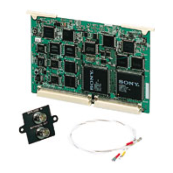
    Aperçu Composants de la DSBK-150 La carte DSBK-150 comprend les éléments suivants. Carte SDI-39 (1) Câbles (2) Plaque à Bouchons de connecteur (2) connecteurs (1)
  • Page 21: Installation

    être faite par un personnel de service qualifié. Préparatifs Avant d’installer la carte dans le magnétoscope, connectez d’abord les deux câbles à plaque à connecteurs. Raccordez le câble rouge au connecteur SDTI IN, et le câble jaune au connecteur SDTI OUT. Câble rouge Câble jaune...
  • Page 22: Procédure D'installation

    Installation Procédure d’installation Retirez le panneau de la batterie du DSR-70/70P (quatre vis) et la plaque couvercle (deux vis). Remarque Prenez garde de ne pas perdre la plaque couvercle ou les vis. Panneau de la batterie Plaque couvercle Insérez la plaque à connecteurs et les câbles attachés dans le trou laissé...
  • Page 23 Eliminez le mou des câbles en les insérant d’abord dans le support de câbles sur la gauche, puis dans celui sur la droite, puis à nouveau dans celui de gauche, comme le montre la figure (gauche et droite sont indiqués de l’arrière du DSR-70/70P).
  • Page 24 Installation Placez la carte SDI-39 au-dessus de l’ouverture laissée par le retrait du panneau de la batterie, et raccordez-y les câbles. Fixez les câbles rouge, orange et jaune aux connecteurs respectifs RED et YEL de la carte. RED: câble rouge YEL: câble jaune Enroulez le serre-câble autour des câbles.
  • Page 25 Leviers Carte SDI-39 Rail de retenue de carte Remarque En abaissant les leviers, l’un ou les deux peuvent ne pas s’asseoir correctement dans le coffret du DSR-70/70P. Si un levier est placé comme indiqué sur le côté droit de la figure ci-dessous, le panneau de la batterie du DSR-70/70P ne se fermera pas.
  • Page 26: Fixation Des Bouchons De Connecteur

    Faites passer les câbles au-dessus des cartes et poussez la partie détendue dans l’espace entre les cartes. Fixation des bouchons de connecteur Quand les connecteurs SDTI IN et SDTI OUT ne sont pas utilisés, insérez les bouchons de connecteur fournis dedans. Bouchons de connecteur...
  • Page 27: Kurzbeschreibung

    Kurzbeschreibung Die DSBK-150 SDTI (QSDI) Input/Output Board ist eine optionale Leiterplatte für den digitalen Videorecorder DSR- 70P von Sony. Bei Installation dieser Leiterplatte läßt sich der Videorecorder an eine EditStation ES-7 für ein digitales, nicht-lineares Schittsystem anschließen. Darüber hinaus ist in einem solchen Fall auch der Anschluß...
  • Page 28: Die Komponenten Der Dsbk-150

    Kurzbeschreibung Die Komponenten der DSBK-150 Die DSBK-150 besteht aus den folgenden Komponenten. Leiterplatte SDI-39 (1) Kabel (2) Anschlußfeld (1) Anschlußkappen (2)
  • Page 29: Installation

    Vorbereitungen Vor der Installation der Leiterplatte in den Videorecorder schließen Sie bitte die zwei Kabel an das Anschlußfeld an. Schließen Sie das rote Kabel an die SDTI IN-Buchse und das gelbe Kabel an die SDTI OUT-Buchse an. Rotes Kabel Gelbes Kabel...
  • Page 30: Einbauverfahren

    Installation Einbauverfahren Entfernen Sie das Akkufeld des DSR-70P (vier Schrauben) und die Abdeckung (zwei Schrauben). Hinweis Achten Sie darauf, die Abdeckung und Schrauben nicht zu verlieren. Akkufeld Schrauben Abdeckung Setzen Sie das Anschlußfeld mit den angeschlossenen Kabeln durch die freie Öffnung der Abdeckung ein. Ziehen Sie die zwei Kabel einzeln durch den Einsteckschlitz des DSR-70P und nach oben.
  • Page 31 Vermeiden Sie Kabeldurchhang, indem Sie sie zuerst durch den linken dann den rechten Kabelhalter, dann wieder den linken und dann rechten, dann erneut durch den linken führen wie in der Abbildung gezeigt (linke und rechte Seite wie von der Rückseite des DSR-70P betrachtet).
  • Page 32 Installation Plazieren Sie die Leiterplatte SDI-39 über die Öffnung wo die Batterieplatte entfernt wurde, und schließen Sie die Kabel an die Leiterplatte an. Schließen Sie das rote Kabel an die RED-Buchse und das gelbe Kabel an die YEL- Buchse an der Leiterplatte an. RED: rotes Kabel YEL: gelbes Kabel Sichern Sie die Kabel mit der Kabelklemme.
  • Page 33 Hebel Leiterplatte SDI-39 Schiene (bitte wenden)
  • Page 34: Anbringen Der Anschlußkappen

    Akkufelds erneut davon, daß die Kabel nicht die Sicherungshebel behindern. Führen Sie die Kabel über die Leiterplatten und verstauen Sie lose Kabelteile in den Freiraum zwischen den Leiterplatten. Anbringen der Anschlußkappen Bei Nichtbeschaltung der SDTI IN- und SDTI OUT-Buchsen setzen Sie die mitgelieferten Anschlußkappen auf. Anschlußkappen...
  • Page 35 Procedimento per l’installazione ........38 Applicazione dei copriconnettori ........42 Presentazione La scheda di ingresso/uscita segnali SDTI (QSDI) DSBK-150 è una scheda opzionale per il videoregistratore per videocassette digitali DSR-70P Sony. L’installazione di questa scheda in un DSR-70P consente al videoregistratore di poter essere collegato ad un’EditStation...
  • Page 36: Presentazione

    Presentazione Componenti della DSBK-150 La DSBK-150 è costituita dalle seguenti parti. Scheda SDI-39 (1) Cavi (2) Pannello connettori (1) Copriconnettori (2)
  • Page 37 Preparativi Prima di installare la scheda nel videoregistratore, collegare innanzitutto i due cavi al pannello connettori. Collegare il cavo rosso al connettore SDTI IN, e il cavo giallo al connettore SDTI OUT. Cavo rosso Cavo giallo Pannello connettori...
  • Page 38: Installazione

    Installazione Procedimento per l’installazione Rimuovere il pannello batteria (quattro viti) e la piastra di copertura (due viti) del DSR-70P. Nota Fare attenzione a non perdere la piastra di copertura o le viti. Pannello batteria Viti Piastra di copertura Inserire il pannello connettori con i cavi collegati nel foro rimasto esposto in seguito alla rimozione della piastra di copertura.
  • Page 39 Eliminare eventuali allentamenti nei cavi inserendo i cavi prima nel fermacavi a sinistra e poi nel fermacavi a destra, quindi di nuovo nel fermacavi a sinistra, come mostrato nella figura (sinistra e destra guardando dal retro del DSR- 70P). alla scheda SDI-39 Fermacavi dal pannello connettori Note...
  • Page 40 Installazione Collocare la scheda SDI-39 sopra l’apertura lasciata esposta in seguito alla rimozione del pannello batteria, e collegare i cavi alla scheda. Collegare il cavo rosso e il cavo giallo ai rispettivi connettori RED e YEL sulla scheda. RED: Cavo rosso YEL: Cavo giallo Applicare il serrafilo ai cavi.
  • Page 41 Levette Scheda SDI-39 Guida di sostegno scheda Nota Quando si abbassano le levette, una di esse o entrambe potrebbero non rientrare saldamente all’interno del rivestimento del DSR-70P. Se una levetta si trova come mostrato sul lato destro della figura sottostante, il pannello batteria del DSR-70P non si chiude.
  • Page 42: Applicazione Dei Copriconnettori

    Accertarsi di far passare i cavi sopra le schede e infilare eventuali parti allentate dei cavi nello spazio tra le schede. Applicazione dei copriconnettori Quando non si usano i connettori SDTI IN e SDTI OUT, applicare i copriconnettori in dotazione ai connettori. Copriconnettori...
  • Page 43 お問い合わせは 「ソニー業務用製品ご相談窓口のご案内」 にある窓口へ   ソニー株式会社 〒141-0001 東京都品川区北品川6-7-35 ソニーマーケティング株式会社 情報システム営業本部 〒108-0074 東京都港区高輪4-10-18 Printed in Japan...

Ce manuel est également adapté pour:

QsdiDsbk-150

Table des Matières