
Manuels Connexes pour HBM VKIA405

Sommaire des Matières pour HBM VKIA405
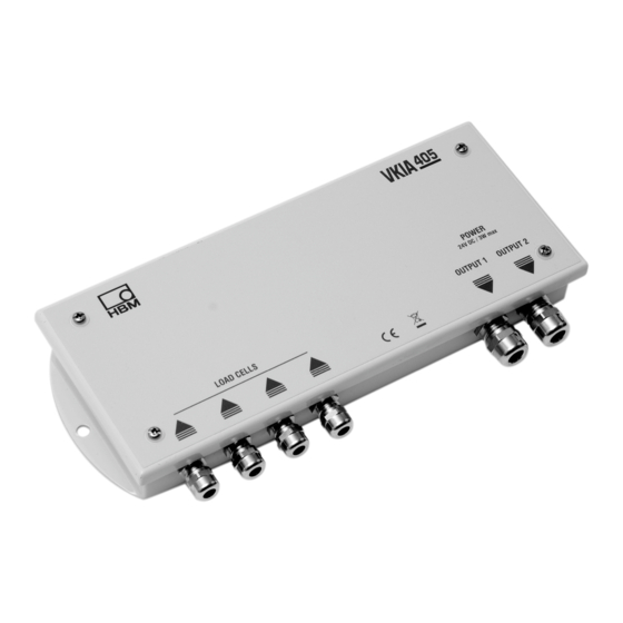
- Page 1 Mounting instructions Montageanleitung Notice de montage Digital Amplifier Digitaler Messverstärker Amplificateur numérique VKIA405 A2448-1.1 en/de/fr...
- Page 2 English ..........Page 3 −...
-
Page 3: Table Des Matières
VKIA405 Contents Page Safety information .......... -
Page 4: Safety Information
VKIA405 Safety information Appropriate use In the interests of safety, the digital amplifier should only be operated as described in the Mounting Instructions. It is also essential to comply with the legal and safety requirements for the application concerned during use. The same applies to the use of accessories. - Page 5 VKIA405 CAUTION Symbol: Meaning: Possibly dangerous situation Warns of a potentially dangerous situation in which failure to comply with safety requirements could lead to damage to property and slight or moderate physical injury. Symbol: NOTE Means that important information about the product or its handling is being given.
- Page 6 Unauthorized conversions and modifications are prohibited The device must not be modified from the design or safety engineering point of view without HBM’s express agreement. Any modification shall exclude all liability by HBM for any damage resulting therefrom. It is strictly forbidden to carry out any repairs and soldering work on the motherboards or to replace any components.
-
Page 7: General
VKIA405 General The digital amplifier VKIA405 is designed for parallel connection of up to 4 load cells. The analog transducer signal from the load cells are first amplified and filtered by the integrated electronics and then converted to a digital value in the analog/digital converter. -
Page 8: Special Features
Mechanical − Parallel connection of max. four load cells in 4 or 6 wire circuit − HBM’s shielding design provides EMC-proofing as per EN 45 501 − Off-center load compensation via the integrated resistor network in the load cell output −... -
Page 9: Mounting The Amplifier
4 ... 6.5 mm 5 ... 9 mm Fig. 3.1: Mounting dimensions The best way to fit the VKIA405 is with the grommets pointing downward. This makes it more difficult for moisture to get in. Top view of housing Tighten the mounting screws in the following sequence: Max. -
Page 10: Preparing The Cables
VKIA405 Preparing the cables For optimum results, proceed as follows: • Remove the outer sheath of the cable and depending on the cable diameter, expose the braided screen for about 10 ...15 mm. • Push the cap nut and the bladed insert with the sealing ring onto the cable. -
Page 11: Connection
VKIA405 Connection The terminals are identified as shown in the following diagram. The colors correspond to the wire colors used for HBM load cells. VKIA405- Load cells Terminals connection Excit. A (blue) Excitation (+) Sense A = (green) Sense (+) -
Page 12: Adjustment Without Weights
Tighten the associated swivel nut in each case to stop the moisture getting in. A termination resistor that can be actuated in the VKIA405 with a slide switch is required for problem-free RS 485 communication. If a single VKIA405 is connected to the control computer, the switch must be set to ”On”. - Page 13 VKIA405 3) Input LDW0; LWT1000000; NOV1000000; COF3; The password must be set for this, see command description AD105C. 4) Query MSV?; and note the value delivered as the answer 5) Input: LDW(noted value); LWT(noted value + Span); The password must be set for this, see command description AD105C.
-
Page 14: Off-Center Load Compensation
Y-axis, read off the resistance and the most suitable combination. The resistance values here apply for 350 ohm load cells (see the table in the lid of the VKIA405). In our example, load cell 3 has an off-center load error of 80 kg, which produces an adjustment resistance of 1.5 + 0.82 ohms (shown in Fig. - Page 15 VKIA405 Load cell 1 Load cell 2 12 600 kg 12 550 kg Test load 12.5 t Load cell 3 Reference load cell 4 12 530 kg 12 450 kg (Example: Reference load cell +80 kg) Fig. 7.1: Example: Platform weighing machine with 4 load cells with 12.5 t test load •...
- Page 16 VKIA405 Fig. 7.3: Alternative method for procedure as in Fig. 7.2 − the dividing points are shown − see table in lid (For 700 ohm load cells, the established value must be doubled.) A2448-1.1 en/de/fr...
-
Page 17: Special Instructions
VKIA405 Special instructions For other test loads types (e.g. building site vehicle testing), the user can extend the chart by drawing an additional line between the zero point and the actual test load used. If the corner load errors are particularly high or if the load cells have an input resistance of more than 350 W, it may be that the total value of the resistor network is insufficient. -
Page 18: Specifications
VKIA405 Specifications Type VKIA405 Accuracy class Resistor network for off-center load com- Ω 0.39...5.71 (in 15 steps) pensation Nominal (rated) voltage Voltage supply 12...30 Nominal (rated) temperature range −10...+50 [+14...+122] °C °C Operating temperature range −20...+70 [−4...+158] [°F] [°F] Storage temperature range −40...+85 [−40...185]... - Page 19 VKIA405 Inhalt Seite Sicherheitshinweise ..........
-
Page 20: Sicherheitshinweise
VKIA405 Sicherheitshinweise Bestimmungsgemäßer Gebrauch Zur Gewährleistung eines sicheren Betriebes darf der digitale Messverstärker nur nach den Angaben in der Montageanleitung verwendet werden. Bei der Verwendung sind zusätzlich die für den jeweiligen Anwendungsfall erforderli- chen Rechts- und Sicherheitsvorschriften zu beachten. Sinngemäß gilt dies auch bei Verwendung von Zubehör. - Page 21 VKIA405 VORSICHT Symbol: Bedeutung: Möglicherweise gefährliche Situation Weist auf eine mögliche gefährliche Situation hin, die − wenn die Sicherheits- bestimmungen nicht beachtet werden − Sachschaden, leichte oder mittlere Körperverletzung zur Folge haben könnte. Symbol: HINWEIS Weist darauf hin, dass wichtige Informationen über das Produkt oder über die Handhabung des Produktes gegeben werden.
- Page 22 Die einschlägigen Unfallverhütungsvorschriften der Berufsgenossenschaften müssen berücksichtigt werden. Verbot von eigenmächtigen Umbauten und Veränderungen Das Gerät darf ohne ausdrückliche Zustimmung von HBM weder konstruktiv noch sicherheitstechnisch verändert werden. Jede Veränderung schließt eine Haftung seitens HBM für daraus resultierende Schäden aus.
-
Page 23: Allgemeines
über Busschnittstellen, nicht zu undefinierten Zuständen oder Datenverlust in der Automatisierungseinrichtung führen. Allgemeines Der digitale Messverstärker VKIA405 ist zur Parallelschaltung von bis zu 4 Wäge- zellen ausgelegt. Das analoge Aufnehmersignal der Wägezellen wird von der inte- grierten Elektronik zunächst verstärkt, gefiltert und im Analog-Digital-Umsetzer in einen Digitalwert umgewandelt. -
Page 24: Charakteristische Merkmale
Störfeldern, zu Messfehlern führen. Charakteristische Merkmale Mechanik − Parallelschaltung von max. vier Wägezellen in 4- oder 6 Leiterschaltung − EMV-Sicherheit gemäß EN 45 501 durch HBM-Schirmungskonzept − Eckenlastabgleich über integriertes Widerstandsnetzwerk im Wägezellen- ausgang − Schutzart IP65 nach EN 60 529 Integrierte Elektronik −... -
Page 25: Montage Des Messverstärkers
4 ... 6,5 mm 5 ... 9 mm Abb. 3.3: Montageabmessungen Der VKIA405 wird vorzugsweise so montiert, dass die Kabeldurchführungen nach un- ten weisen. Damit wird der Schutz gegen eindringende Feuchtigkeit erhöht. Draufsicht des Gehäuses Montageschrauben in folgender Reihenfolge anziehen: Max. -
Page 26: Konfektionierung Der Kabel
VKIA405 Konfektionierung der Kabel Um optimale Ergebnisse zu erzielen, ist wie folgt vorzugehen: • Außenmantel des Kabels abtrennen und Schirmgeflecht je nach Kabeldurch- messer auf ca. 10...15 mm freilegen. • Hutmutter und Lamelleneinsatz mit Dichtring auf das Kabel schieben. • Schirmgeflecht rechtwinklig (90°) nach außen biegen. -
Page 27: Anschließen
VKIA405 Anschließen Die Klemmen sind auf der Platine bezeichnet. Die Farbangabe entspricht den Aderfarben der meisten HBM-Wägezellen. VKIA405- Wägezellen- Klemmenbez. Anschluss Excit. A (blau) Speisung (+) Sense A = (grün) Fühler (+) In A (weiß) Signal (+) In B (rot) Signal (−) Sense B = (grau) Fühler (−) -
Page 28: Abgleich Ohne Gewichte
Eindringen von Feuchtigkeit vermieden wird. Für die störungsfreie RS-485-Kommunikation wird ein Abschlusswiderstand benötigt, der im VKIA405 per Schiebeschalter aktivierbar ist. Wenn nur ein einzelner VKIA405 mit dem Steuerrechner verbunden ist, muss der Schalter auf ”On” eingestellt werden. Bei mehreren Geräten am Bus darf nur ein Schal- ter aktiviert sein, die übrigen sind auf ”Off”... - Page 29 VKIA405 Die Vorlast (Aussteuerung bei unbelastetem Aufbau) wird durch den Wert LDW berücksichtigt. Dieser kann von einer gleichartigen Waage übernommen oder wie folgt gemessen werden: 3) Eingabe LDW0; LWT1000000; NOV1000000; COF3; Dazu muss das Passwort gesetzt sein, siehe Befehlsbeschreibung AD105C.
-
Page 30: Eckenlastabgleich
Achse den Widerstand und die bestpassende Kombination ablesen. Die Wi- derstandswerte gelten hier für 350-W-Wägezellen (siehe Tabelle, eingeklebt im Deckel des VKIA405). Im Beispiel hat die Wägezelle 3 einen Eckenlastfehler von 80 kg, das ergibt einen Abgleichwiderstand von 1,5 + 0,82 (in Abb. 7.1 gekennzeichnet). - Page 31 VKIA405 Wägezelle 1 Wägezelle 2 12 600 kg 12 550 kg Prüflast 12,5 t Wägezelle 3 Bezugs-Wägezelle 4 12 530 kg 12 450 kg (Beispiel: Bezugs-Wägezelle +80 kg) Abb 7.2: Bsp.: Brückenwaage mit vier Wägezellen bei 12,5 t Prüflast • Für die betreffende Wägezelle (z.B. Wägezelle 3) werden die notwendigen Widerstände durch Auftrennen des entsprechenden “0-W-Widerstands”...
- Page 32 VKIA405 Abb. 7.3: Alternativmethode zum Verfahren nach Abb. 7.2 − gezeigt sind die Auftrennpunkte − siehe Tabelle im Deckel (Für 700-W-Wägezellen ist der ermittelte Wert zu verdoppeln.) A2448-1.1 en/de/fr...
-
Page 33: Spezielle Hinweise
VKIA405 Spezielle Hinweise Bei anderen Prüflasten (z.B. Prüfung mit Baustellenfahrzeug) kann das Dia- gramm vom Anwender erweitert werden, indem eine weitere Linie zwischen Nullpunkt und der verwendeten Prüflast gezogen wird. Im Falle von besonders großen Eckenlastfehlern oder bei Wägezellen mit Ein- gangswiderstand von mehr als 350 W kann es vorkommen, dass der Gesamt- wert des Widerstandsnetzwerks nicht ausreicht. -
Page 34: Technische Daten
VKIA405 Technische Daten VKIA405 Genauigkeitsklasse Ω Widerstandsnetzwerk für Eckenlastabgleich 0,39...5,71 (in 15 Stufen) Nennspannung Spannungsversorgung 12...30 Nenntemperaturbereich −10...+50 °C Gebrauchstemperaturbereich −20...+70 Lagerungstemperaturbereich −40...+85 Luftfeuchtigkeit, rel., nicht kondensierend 5...85 Gewicht, ca. Schutzart nach EN 60529 IP65 (staubdicht und gegen Strahlwas- (IEC 529) ser geschützt) - Page 35 VKIA405 Sommaire Page Consignes de sécurité ..........
-
Page 36: Consignes De Sécurité
VKIA405 Consignes de sécurité Utilisation conforme Pour garantir un fonctionnement de l’amplificateur numérique en toute sécurité, celuici doit être utilisé conformément aux instructions de la notice de montage. De plus, il convient, pour chaque cas particulier, de respecter les règlements et consignes de sécurité... - Page 37 VKIA405 Dans la présente notice de montage, les dangers résiduels sont signalés à l’aide des symboles suivants : Symbole : REMARQUE Signale que des informations importantes concernant le produit ou sa manipulation sont fournies. ATTENTION Symbole : Signification : Situation éventuellement dangereuse Signale un risque potentiel qui, si les dispositions relatives à...
- Page 38 Interdiction de procéder à des transformations et modifications sans accord préalable Il est interdit de modifier cet appareil sur le plan conceptuel ou celui de la sécurité sans accord explicite de HBM. HBM ne pourra en aucun cas être tenu responsables des dommages qui résultent d’une modification quelconque.
-
Page 39: Généralités
Généralités Avec l’amplificateur numérique VKIA405, il est possible de raccorder jusqu’à 4 pesons en parallèle. Le signal analogique des pesons est tout d’abord amplifié par l’électronique intégrée, puis filtré et converti en une valeur numérique par le convertisseur analogique-numérique. -
Page 40: Caractéristiques Spécifiques
Mécanique − Branchement en parallèle de quatre pesons maxi. en liaison 4 ou 6 fils − CEM selon EN 45 501 grâce au concept de blindage HBM − Équilibrage des charges d’angle par réseau de résistances intégré dans la sortie du peson −... -
Page 41: Montage De L'amplificateur De Mesure
5 à 9 mm Fig. 3.5 : Dimensions de montage Il est préférable de monter le VKIA405 avec les passages de câbles orientés vers le bas de façon à augmenter la protection contre toute pénétration d’humidité. Vue de dessus du boîtier Serrer les vis de fixation dans l’ordre suivant :... -
Page 42: Confection Des Câbles
VKIA405 Confection des câbles Pour obtenir les meilleurs résultats, procéder comme suit : • Retirer la gaine extérieure du câble et dénuder la tresse de blindage sur 10 à 15 mm environ selon le diamètre du câble. • Enfiler l’écrou borgne et la pièce à lamelles avec la bague d’étanchéité sur le câble. -
Page 43: Raccordement
VKIA405 Raccordement Les bornes sont désignées conformément au schéma ci-dessous. Les couleurs correspondent au code de couleurs de la plupart des pesons HBM. VKIA405- Pesons bornes connectuers Excit. A (bleu) Alimentation (+) Sense A = (vert) Élém. sensible (+) In A... -
Page 44: Ajustement Sans Poids
Pour une communication RS-485 sans parasitage, il est nécessaire d’installer une résistance de terminaison activable par interrupteur à coulisse dans le VKIA405. Si seul un VKIA405 est relié à l’ordinateur de contrôle, l’interrupteur doit être réglé sur ”On”. En présence de plusieurs appareils sur le bus, seul un interrupteur doit être activé... - Page 45 VKIA405 La charge morte (niveau de contrôle sans charge) est prise en compte par la valeur LDW. Cette dernière peut être reprise d’une balance équivalente ou mesurée de la manière suivante : 3) Saisir LDW0, LWT1000000, NOV1000000, COF3. Pour ce faire, le mot de passe doit être défini, voir la description des commandes AD105C.
-
Page 46: Équilibrage Des Charges D'angle
On peut alors lire sur l’axe Y la résistance et la combinaison la mieux adaptée. Les valeurs de résistance indiquées ici s’appliquent à des pesons de 350 W (voir tableau collé dans le couvercle du VKIA405). Dans l’exemple choisi, le peson 3 présente une erreur d’excentricité de 80 kg, ce qui donne une résistance d’équilibrage de 1,5 + 0,82 (voir Fig. - Page 47 VKIA405 Peson 1 Peson 2 12 600 kg 12 550 kg Charge d’épreuve 12,5 t Peson 3 Peson de référence 4 12 530 kg 12 450 kg (Exemple : peson de référence +80 kg) Fig. 7.3 : Exemple d’un pont bascule à...
- Page 48 VKIA405 La valeur calculée doit être multipliée par deux pour des pesons de 700 W. Charge d’essai séparer Erreur d’excentricité entre reporter au mode d’emploi séparer ne pas ouvrir Fig. 7.3 : Méthode alternative à la méthode de la fig. 7.2 −...
-
Page 49: Consignes Particulières
VKIA405 Consignes particulières En cas de charges d’épreuve différentes (par ex. contrôle avec un véhicule de chantier), l’utilisateur peut étendre le graphique en traçant une ligne supplémentaire entre le zéro et la charge d’épreuve utilisée. En présence d’erreurs d’excentricité particulièrement importantes ou pour des pesons ayant une résistance d’entrée de plus de 350 W, il peut arriver que la... -
Page 50: Caractéristiques Techniques
VKIA405 Caractéristiques techniques Type VKIA405 Classe de précision Réseau de résistances pour l’équilibrage Ω 0,39...5,71 (15 niveaux) des charges d’angle Tension nominale C.C. Tension d’alimentation 12...30 C.C. Plage nominale de température −10...+50 °C Plage utile de température −20...+70 Plage de température de stockage −40...+85... - Page 51 VKIA405 A2448-1.1 en/de/fr...
- Page 52 Elles n’établissent aucune assurance formelle au terme de la loi et n’engagent pas notre responsabilité. Hottinger Baldwin Messtechnik GmbH Im Tiefen See 45 ⋅ 64293 Darmstadt ⋅ Germany Tel. +49 6151 803-0 ⋅ Fax: +49 6151 803-9100 Email: info@hbm.com ⋅ www.hbm.com...