Publicité

Les langues disponibles

Les langues disponibles

Liens rapides

KOMBISCHWEISSGERÄT
S-Multi
41 / 51 /41P / 51P
BEDIENUNSANLEITUNG
User manual | Manuel d´utilisation | Istruzioni per l'uso | Manual de instrucciones

Publicité

Table des Matières
loading

Sommaire des Matières pour STAMOS S-Multi 41

  • Page 1 KOMBISCHWEISSGERÄT S-Multi 41 / 51 /41P / 51P BEDIENUNSANLEITUNG User manual | Manuel d´utilisation | Istruzioni per l‘uso | Manual de instrucciones...
  • Page 2 INHALT | CONTENT | CONTENU | CONTENIDO | TREŚĆ Diese Bedienungsanleitung beinhaltet Beschreibungen, Bedienungsanleitungen und grundsätzliche Wartungsvorgänge für die Stamos Germany KOMBISCHWEIßGERÄTE S Multi 41 / 51 /41P / 51P. Studieren Sie diese Bedienungsanleitung ausführlich. Ein vollständiges Verständnis der Eigenschaften und der Einsatzmöglichkeiten des Gerätes gewährleistet die sachgemäße Anwendung.
  • Page 3 Schweißen Sie nicht an geschlossenen Behältern wie z.B. ELEKTRISCHER SCHOCK IST LEBENSGEFÄHRLICH. Tanks oder Fässern • Berühren Sie nie aufgeladene elektrische Teile. Verbinden Sie die Arbeitskabel, so praktisch wie möglich, mit einer in der Nähe des • Tragen Sie trockene, nicht durchlöcherte isolierte Handschuhe und Arbeitsplatz liegenden Steckdose, um zu vermeiden, dass das Stromkabel im ganzen Körperschutz.
  • Page 4 • Reparieren oder ersetzen Sie bitte umgehend beschädigte Bestandteile des FLIEGENDE FUNKEN können Verletzungen verursachen. Gerätes. • Tragen Sie einen Gesichtschutz oder Sicherheitsbrille mit Seitenabdeckung. • Tragen Sie ein Sicherheitsgurt, wenn Sie in Höhen arbeiten. • Tragen Sie geeigneten Körperschutz um die Haut zu schützen. •...
  • Page 5 Leistungen müssen sofort ausgetauscht werden. Der Hersteller kann nicht haftbar gemacht werden, wenn das Gerät technisch verän- • Bei längeren Arbeitspausen ist das Gerät auszuschalten. dert wird oder wenn nach solchen Veränderungen Schäden entstehen. • Nach Beendigung der Arbeiten oder bei einem Standortwechsel ist immer der Netzstecker zu ziehen.
  • Page 6 Strom zur Elektrode geführt wird und das Plasma mit dem zu bearbeitenden Metall in halten. Lichtbogen-schweißen wird im Hochbau (Brückenträger), aber auch in der Kontakt bleibt. Die Schneidedüse hat eine zweite Gruppe von Kanälen. Diese Kanäle Feinmechanik angewandt. Dabei gilt: Je dünner das Material, desto aufwändiger die entlassen einen konstanten Fluss an Schutzgas um den Ausrüstung, da die niedrigen Stromstärken (um Materialien unter 1 mm Wandstärke Der Druck dieses Gasflusses...
  • Page 7: Duty Cycle

    Eigenschaften dieser Modellreihe: Der automatische Stromunterdrückungs-Kreislauf schützt vor Überspannung bis zu dem im technischen Datenblatt beschriebenen Wert. ZERTIFIKATE = Dieses Schweißgerät wurde nach den RoHS strengen europäischen Vorgaben und Regeln produziert und ist somit CE-zertifiziert und RoHS-konform. Wärmeschutz Eine lange Haltbarkeit sowie maximale Qualität dieses Gerätes wird damit garantiert.
  • Page 8 ANTI-STICK = Diese Funktion verhindert das Ausglühen der POST TIME = Gasnachströmzeit regelbar in Sekundenintervallen.Diese Elektrode, da der Strom automatisch verringert wird. Regulierung ist wichtig um das geschmolzene Schweißgut nach dem Schweißvorgang zu kühlen und vor Oxidation zu schützen. SCHUTZGAS = Für das WIG / TIG Schweißen ist ein Schutzgas nötig (z.B.
  • Page 9 WIG-/TIG-/PLASMASCHNEIDERANSCHLÜSSE Massekabelanschluss Im Gegensatz zu den Metall-Schutzgasverfahren MIG/MAG brennt der Lichtbogen beim WIG-Schweißen zwischen einer nicht abschmelzenden Wolframelektrode und dem Grundwerkstoff. Zum Schutz von Wolframelektrode und Schmelzbad sind Hinter jedem Schweißgerät befindet sich eine Schraube und eine inerte Gase wie Argon oder Helium bzw. Gasgemische mit nicht Markierung, um die erforderliche Erdung vorzunehmen.
  • Page 10 Geräteansicht Zubehör 1. Elektrodenhalter MMA 6. Luftschlauch 2. Verschleissteile WIG/TIG 7. Tasche 3. Druckventil + Manometer 8. Plasmabrenner 4. Verschleissteile Plasmaschneider 9. TIG/WIG-Schlauch 5. Masseklemme 10. Bürste...
  • Page 11: Technische Details

    425x205x355 dauer stark. Schutzklasse IP21 C. Kabeleingangsverbindung S-Multi 41 / 41P Jedes Gerät verfügt über ein Hauptstromkabel, das dafür zuständig ist, die Stromstärke Netz-Frequenz (Hz) 50/60 und Spannung für dieses Gerät herzustellen. Wenn das Gerät mit Strom verbunden ist, Zündung...
  • Page 12 B. Schneiden E. Vorgang des Pistolenlaufbaus 1. Drag- Schneiden Stellen Sie die Pistole mit der Schutzkappe nach oben zeigend auf, und drehen Halten Sie die Pistolenspitze seicht über den Arbeitsgegenstand, drücken Sie den Sie die Schutzkappe, von der Pistole ab. (Schutzkappe hält die Spitze, den Keramik- Pistolenschalter und bewegen Sie die Pistolenspitze bis es zum Kontakt mit dem drehungsring, und die Elektrode zusammen).
  • Page 13 Nehmen Sie die Pistole in die Hand und drehen Sie erst mal die kleine schwarze Ver- Schweißstromstärke und der Bogen hört sofort auf zu arbeiten. schlusskappe (Back Cup ab). Drehen Sie nun stattdessen den langen schwarzen Ver- Die Schweißfackel kann nicht abgenommen werden, bevor der Bogen nicht zum schluss auf.
  • Page 14 SAVE THIS MANUAL Keep this manual for the safety warnings and precautions, assembly, operating, in- spection, maintenance and cleaning procedures. Write the product’s serial number in the back of the manual near the assembly diagram (or month and year of purchase if product has no number).
  • Page 15: Electrical Safety

    2. Do not operate power tools in explosive atmospheres, such as in Personal Safety the presence of flammable liquids, gases, or dust. Power tools create 1. Stay alert. Watch what you are doing, and use common sense sparks which may ignite the dust or fumes. when operating a power tool.
  • Page 16 6. Maintain tools with care. Keep cutting tools maintained and clean. 7. Prevent eye injury and burns. Wearing and using the approved personal safe- Properly maintained tools are less likely to bind and are easier to control. Do not ty clothing and safety devices reduce the risk for injury. use a damaged tool.
  • Page 17 h. Dangerously reactive or flammable gases, vapors, liquids, and dust. • Follow OSHA guidelines for Permissible Exposure Limits (PEL’s) for various i. Provide adequate ventilation in work areas to prevent accumulation of fumes and gases. flammable gases, vapors, and dust. Do not apply heat to a container that •...
  • Page 18: Manual Arc Welding

    Manual arc welding troduced in Germany. In English-speaking countries this method is called TIG, after the English word for tungsten. The method offers several interesting advantages over other Manual arc welding, briefly called MMA (Manual Metal Arc Welding), is one of the ol- fusion welding processes.
  • Page 19 Properties of this model range: Duty Cycle The duty cycle is the percentage of the operating time (measured in minutes) of a CERTIFICATES = this welder was produced according to RoHS 10-minute period in which the machine is used continuously in normal temperature strict European regulations and rules and is therefore CE conditions.
  • Page 20 ANTI-STICK = This feature prevents overheating of the electrode, by POST TIME = gas flow variable at second intervals. This regulation is reducing the current automatically. important for the cooling of the melted weld metal after the welding process and to protect against oxidation. GAS PROTECTION = For TIG welding an inert gas is necessary (e.g.
  • Page 21 TIG-/PLASMA TORCH CONNECTION Grounding cable connection Unlike the metal-inert gas MIG/MAG, in TIG welding the arc burns bet- ween a non-consumable tungsten electrode and the base material. In order to protect the tungsten electrode and the weld pool it is necessa- ry to use inert gases, such as argon or helium or gas mixtures with non- At the back of each welder there is a screw and a label to provide the oxidizing components.
  • Page 22: Accessories

    Machine view Accessories 1. MMA electrode holder 6. Air hose 2. WIG / TIG wearing parts 7. Bag 3. Pressure valve and manometer 8. Plasma torch 4. Wearing parts plasma torch 9. TIG/WIG hose 5. Grounding clamp cable 10. Brush...
  • Page 23 Each unit is equipped with a main power cable, which is responsible for providing cur- rent and voltage to the device. If the device is connected to power which exceeds the S-Multi 41 / 41P required voltage, or if the wrong phase is set, it may lead to severe damage to the unit.
  • Page 24 E. Assembling the pistol Put the pistol the protective cap facing up and turn the cap away from the gun. (The 2. Weekly activities protective cap holds the tip, the ceramic swirl ring and the electrode together). Re- Verify the proper operation of the air flow. Blow off or suck in dust or dirt from the move the cap, the ceramic swirl ring and the electrode.
  • Page 25: Working Procedures

    WORKING PROCEDURES Manual welding with electrode • Connect the MMA hose to the minus pole (-). • Set the current control to the appropriate welding current (pulse current con- Argon arc welding (TIG) trol to minimum position). Use the empirical formula: I = 40d, d is the diameter Cleaning before welding of the electrode.
  • Page 26: Instrukcja Obsługi

    Niniejsza instrukcja obsługi zawiera opisy, instrukcje oraz podstawowe informacje dotyczące obsługi spawarek uniwersalnych S Multi 41 / 51 /41P / 51P. Przed uruchomieniem urządzenia należy dokładnie zapoznać się z instrukcją. Dokładne zrozumienie cech i możliwości zastosowania urządzenia gwarantuje jego zastosowanie zgodne z przeznaczeniem UWAGA •...
  • Page 27 Nie wolno spawać w pobliżu zbiorników lub beczek z substancjami PORAŻENIE ELEKTRYCZNE JEST NIEBEZPIECZNE dla życia i łatwopalnymi. zdrowia. Kabel zasilający należy podłączyć do najbliżej położonego gniazda i ułożyć w sposób • Nie wolno dotykać elementów znajdujących się pod napięciem elektrycznym. praktyczny i bezpieczny.
  • Page 28 dala od ciała. PROMIENIOWANIE ŁUKU ELEKTYCZNEGO może uszkodzić wzrok • Przymocuj kabel roboczy do właściwego metalowego styku elementu i skórę ciała. spawanego (nie do elementu, który może odpaść) lub do stołu roboczego na • Należy stosować ochronę twarzy (hełm lub osłonę) i oczu z okularem o tyle blisko spawarki, na ile wydaje się...
  • Page 29 • Dzieciom nie wolno użytkować spawarki. Osoby nieletnie należy trzymać z PLASMA dala od urządzenia • Urządzenie należy przechowywać w suchym i czystym pomieszczeniu. Ogólne informacje na temat cięcia plazmą • Należy przestrzegać przepisów BHP. Przez palnik plazmowy przepływa pod wysokim ciśnieniem gaz np.: powietrze, który •...
  • Page 30 Informacje dotyczące rodzaju, właściwości oraz zastosowania elektrody podaje skrót Inne zalety tej metody to: typu elektrody na opakowaniu. Otulina elektrody podczas topnienia wydziela gazy, • metoda ta nadaje się w szczególności do spawania połączeń krawędziowych które oprócz stabilizacji łuku elektrycznego chronią płynny metal przed wpływem (graniowych) oraz połączeń...
  • Page 31 Cechy urządzeń: NATĘŻENIE PRĄDU Napięcie źródła prądu: AC220/230/240 ±10% CERTYFIKATY = Spawarka WIG SEP-200 została wykonana RoHS Częstotliwość 50/60Hz według surowych norm europejskich oraz przeszła badanie pod kątem zgodności z CE oraz RoHS. Gwarantuje to długą Kontrolka z przodu urządzenia zaświeci się. Wentylator będzie prawdopodobnie żywotność...
  • Page 32 ANTI-STICK = funkcja ta zapobiega wypalaniu elektrody, ponieważ POST TIME = czas dopływu gazu po zaniku łuku elektrycznego jest natężenie prądu zostanie automatycznie zmniejszone. regulowany w przedziałach sekundowych. Funkcja regulacji tego czasu jest nie bez znaczenia dla stopionej spoiny, którą po zakończeniu spawania należy schłodzić...
  • Page 33 WIG/TIG = w przeciwieństwie do spawania metali w osłonie gazu Złącze przewodu masy MIG/MAG, podczas spawania metodą WIG łuk elektryczny powstaje pomiędzy nietopliwą elektrodą wolframową a materiałem spawanym. W celu ochrony elektrody wolframowej oraz spoiny stosuje się gazy obojętne takie jak argon i hel lub nie utleniające mieszanki gazowe. Spawanie metodą...
  • Page 34: Wyposażenie Dodatkowe

    WIDOK URZADZENIA Z PRZODU Wyposażenie dodatkowe 1. Uchwyt elektrody MMA 6. Wąż powietrzny 2. Części podlegające zużyciu WIG/TIG 7. Torba 3. Zawór ciśnieniowy + manometr 8. Palnik plazmowy 4. Części podlegające zużyciu palnika plazmowego 9. Wąż TIG/WIG 5. Zacisk masy 10.
  • Page 35: Dane Techniczne

    Dane techniczne URUCHOMIENIE S-Multi 51 / 51P Częstotliwość sieci (Hz) 50/60 A. Rozpakowanie Zapłon HF wysokiej styk styk Wypakuj wszystkie rzeczy z opakowania i upewnij się, czy są wszystkie przedmioty częstotliwości wyszczególnione w zakresie dostawy. Napięcie jałowe (V) Prąd wejściowy (A) 23,5 B.
  • Page 36 E. Postępowanie przy montażu palnika B. Ciecie Palnik/pistolet wraz z kapturkiem ochronnym należy ustawić w pionie kapturkiem do 1. Cięcie kontaktowe góry. Następnie okręcić kapturek. Kapturek zawiera końcówkę, ceramiczny pierścień Palnik należy przytrzymać blisko przy powierzchni przedmiotu obrabianego. Po wirujący oraz elektrodę. Zdejmujemy najpierw kapturek, ceramiczny pierścień wirujący naciśnięciu włącznika należy dotknąć...
  • Page 37: Sposób Użytkowania

    Uchwyt należy wziąć do ręki oraz odkręcić czarny korek zamykający. Następnie należy Spawanie ręczne za pomocą elektrody wprowadzić do tulejki elektrodę wolframową. Na tulejkę nasunąć obudowę tulejki i • Podłączyć przewód E-Hand do bieguna ujemnego (-). dokręcić od przodu głowicę uchwytu. •...
  • Page 38: Poste À Souder Combiné

    Cette notice comprend des descriptions, des instructions d‘emploi et des conseils d‘entretien de base pour les postes à souder combinés Stamos Germany S Multi+ 41/51 /41P/51P. Étudiez attentivement ces instructions. Une bonne compréhension des caractéristiques et des capacités de l‘appareil en garantit une utilisation correcte.
  • Page 39 Ne soudez pas (sur) des récipients fermés comme p. ex. des réser- UN CHOC ELECTRIQUE PEUT ENTRAINER LA MORT. voirs ou des tonneaux. • Ne touchez jamais les éléments électriques sous tension. • Portez des gants et protections corporelles secs, isolants et en parfait état. Dans la mesure du possible, reliez le cordon d‘alimentation de l‘appareil à...
  • Page 40 • Réparez ou remplacez immédiatement toute pièce endommagée de l’appareil. Les ÉTINCELLES peuvent entraîner des blessures. • Portez une sangle de sécurité si vous travaillez en hauteur. • Portez un masque de protection ou des lunettes de sécurité avec protection •...
  • Page 41 L’appareil ne doit pas être ouvert, cela entraîne automatiquement l’extinction de la • Les éléments isolants de la torche, le câble et tout élément de l’article qui garantie. s’avère endommagé doit être remplacé immédiatement. • Pendant de longues interruptions, l’appareil doit être mis hors-circuit. Le fabricant ne peut pas être tenu responsable d’éventuels dommages dus ou provo- •...
  • Page 42: Soudage Manuel À L'arc

    de protection. La pression exercée par ce flux de gaz contrôle le rayon du faisceau de construction des ponts,..), mais également dans la mécanique de précision. En pratique: plasma. plus le matériau est mince, plus l’équipement est onéreux, puisque les machines qui disposent d’un faible ampérage (spécialement conçues pour ne pas griller les matériaux Indication! Cette machine est conçue pour utiliser uniquement l’air comprimé...
  • Page 43: Caractéristiques De Cette Gamme

    Caractéristiques de cette gamme: Réglage du courant CERTIFICATS = ce poste à souder a été produit dans le strict Le dispositif anti surtension protège l’appareil jusqu’aux valeurs inscrites sur la fiche RoHS respect des normes et règles européennes et est ainsi certifié technique.
  • Page 44 ANTI-STICK = cette fonction empêche l’électrode POST TIME = L’écoulement du gaz peut être réglé à la seconde près. de brûler, puisque le courant est réduit automatiquement. Ce réglage est essentiel pour le refroidissement du poste après utilisation et pour protéger l’appareil contre les risques d’oxydation. GAZ PROTECTEUR = L’utilisation d’un gaz protecteur est nécessaire pour le soudage TIG (p.
  • Page 45 WIG-/TIG-/Raccords du découpeur Plasma Raccords des câbles de masse Contrairement au procédé de soudage MIG/MAG (qui utilise un gaz de protection du métal), le soudage WIG fonctionne ainsi: l’arc électrique se forme entre une électrode non fusible en tungstène et le matériau de base.
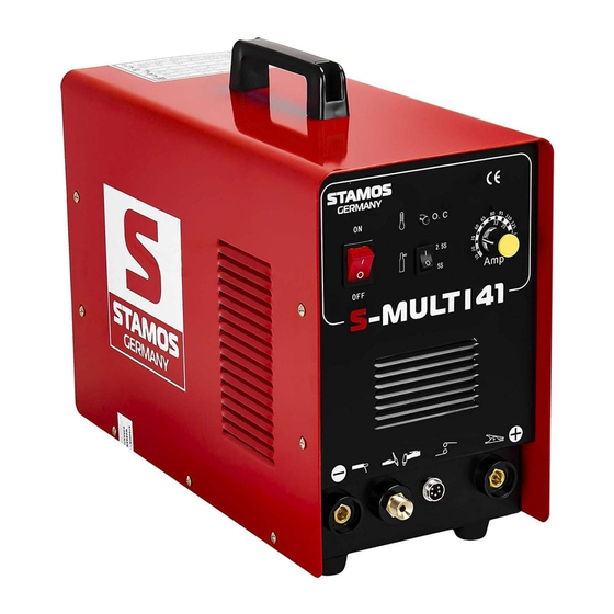
  • Page 46: Aperçu De L'article

    Aperçu de l’article Accessoires 1. Porte électrode MMA 6. Durite 2. Consommables WIG/TIG 7. Sac 3. Valve de pression + manomètre 8. Torche plasma 4. Pièces d’usure coupeur plasma 9. Câble TIG/WIG 5. Pince de masse 10. Brosse...
  • Page 47: Détails Techniques

    Si la machine est utilisée sans le refroidissement approprié, la durée du facteur de Classe de protection IP21 marche en sera grandement réduite. S-Multi 41 / 41P C. Branchement des câbles Fréquence du secteur (Hz) 50/60 Chaque appareil est équipé d‘un cordon d‘alimentation permettant l‘apport en courant Amorçage...
  • Page 48: Entretien Hebdomadaire

    E. Assemblage de la torche B. Découpe Inclinez la torche avec son capuchon de protection vers le haut et dévissez ce dernier. 1. Découpe en contact continu (drag cutting) (Le bouchon maintient la pointe, le diffuseur en céramique Tenir le diffuseur du pistolet au-dessus de la pièce d‘ouvrage, appuyer sur l‘interrupteur et l‘électrode ensemble).
  • Page 49: Procédés De Travail

    Prenez la torche en main et tournez d’abord le petit capuchon de fermeture noir (Back Lorsque la pression sur la gâchette est relâchée, la puissance du courant de soudage Cup). Tournez maintenant le long capuchon noir. Introduisez l‘électrode de tungstène diminue et l‘arc disparaît immédiatement.
  • Page 50 NOTIZEN | NOTES Hiermit bestätigen wir, dass die hier in dieser Anleitung aufgeführten Geräte CE- konform sind. We hereby certify that the appliances listed in this manual are CE compliant. Par la présente, nous confirmons que les appareils présentés dans ce mode d´emploi sont conformes aux normes Ce.
  • Page 51 Umwelt- und Entsorgungshinweise Hersteller an Verbraucher Sehr geehrte Damen und Herren, gebrauchte Elektro- und Elektronikgeräte dürfen gemäß europäischer Vorgaben [1] nicht zum unsortierten Siedlungsabfall gegeben werden, sondern müssen getrennt erfasst werden. Das Symbol der Abfalltonne auf Rädern weist auf die Notwendigkeit der getrennten Sammlung hin.

Ce manuel est également adapté pour:

S-multi 51S-multi 41pS-multi 51p

Table des Matières