Table des Matières
Publicité
Les langues disponibles
Les langues disponibles
Liens rapides
CEDES
Installation and Operation Manual
Bedienungsanleitung
Mode d'emploi
Manuale d'installazione e d'uso
Instrucciones de montaje y uso
Instrukcja obsługi
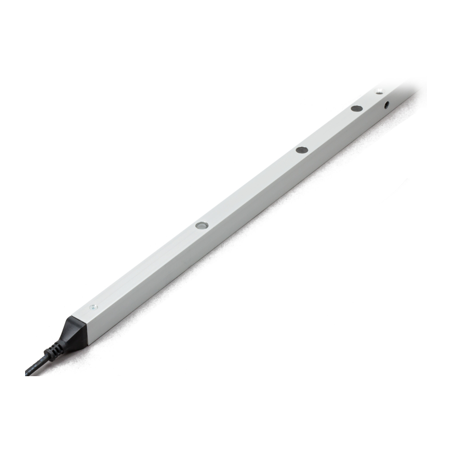
cegard/Mini
Light curtain for elevator doors
English
Deutsch
Français
Italiano
Español
Polski
IMPORTANT NOTE
FOLLOW THE INSTRUCTIONS GIVEN IN THIS MANUAL CAREFULLY. FAILURE TO DO
SO MAY CAUSE CUSTOMER COMPLAINTS AND SERIOUS CALL BACKS. KEEP IN-
STRUCTION MANUAL ON SITE.
© CEDES
105 235 I 121003 I V 2.3
Publicité
Table des Matières

Manuels Connexes pour Cedes cegard/Mini


Sommaire des Matières pour Cedes cegard/Mini
-
Page 14: Information Importante
RESPECT PEUT ENTRAÎNER DES PLAINTES DE CLIENTS OU DES MESURES DE RAP- PEL. CONSERVEZ CE MODE D’EMPLOI À PROXIMITÉ DE L’INSTALLATION. INFORMATIONS IMPORTANTES LORSQU’UN RIDEAU LUMINEUX CEGARD/MINI EST UTILISÉ EN REMPLACEMENT DE BORDS DE SÉCURITÉ MÉCANIQUES, IL EST DE LA RESPONSABILITÉ DE L’INSTALLATEUR DE GARANTIR QU’UNE FOIS ACHEVÉE, L’INSTALLATION RES- PECTE TOUTES LES LOIS ET PRESCRIPTIONS NATIONALES ET LOCALES EN VI- GUEUR POUR LES DISPOSITIFS DE SÉCURITÉ... -
Page 15: Description Du Fonctionnement
Caractéristiques principales Introduction • Design robuste et extrêmement compact. Le rideau lumineux à infrarouge cegard/Mini se • Pas de mise à la terre nécessaire. compose d’un bord émetteur (Tx) et d’un bord récep- • Durée de vie de plus de 20 ans grâce à : teur (Rx) avec chacun un contrôleur intégré. - Page 16 être considéra- Bien que cegard/Mini soit très peu sensible à la lu- blement réduite. Les câbles peuvent également être mière étrangère, il est toutefois préférable de monter endommagés s’ils oscillent ou restent accrochés...
- Page 17 La fonction d’inhibition des rayons n’est pas possible si la protection du camp réduit est activée. 5. Connexion et test de fonctionnement Une fois le cegard/Mini correctement installé, l’alimentation en tension peut être connectée. Chaque bord (Rx et Tx) comporte un affichage optique (DEL verte) indiquant l’état du rideau lumineux.
- Page 18 ; d. que les éléments optiques des bords sont pro- pres (exempts de poussière et salissures). Bien que le cegard/Mini soit très peu sensible aux sa- lissures, ses performances sont nettement meil- leures si les bords sont propres.
-
Page 19: Caractéristiques Techniques
Mode d’emploi Recyclage cegard/Mini ne contient aucun matériau nuisible. De tels matériaux ne sont pas non plus utilisés pour sa fabrication. Les composants électroniques peuvent Le rideau lumineux ne peut être remplacé que si un présenter des traces de substances nuisibles, mais dispositif de protection de porte semblable est mis pas dans des quantités nocives pour la santé. - Page 20 RECLAMI DA PARTE DEI CLIENTI O A RICHIESTE DI RESTITUZIONE DEL PRODOTTO. CONSERVARE QUESTO MANUALE DI ISTRUZIONI NEI PRESSI DELL’IMPIANTO. INFORMAZIONI IMPORTANTI SE LA BARRIERA FOTOELETTRICA CEGARD/MINI VIENE UTILIZZATA IN ALTERNATI- VA AI DISPOSITIVI MECCANICI DI SICUREZZA, L’INSTALLATORE DOVRÀ GARANTIRE CHE AL COMPLETAMENTO DEL MONTAGGIO L’IMPIANTO SIA CONFORME A TUTTE LE NORME E I REGOLAMENTI NAZIONALI E LOCALI IN VIGORE PER I DISPOSITIVI DI PROTEZIONE PORTE A RAGGI INFRAROSSI E FOTOELETTRICI.