Table des Matières
Publicité
Les langues disponibles
Les langues disponibles
Liens rapides
Publicité
Table des Matières

Manuels Connexes pour Watts WFHC-MASTERH&C-BUS & SLAVE


Sommaire des Matières pour Watts WFHC-MASTERH&C-BUS & SLAVE
- Page 1 WFHC-MASTERH&C-BUS SLAVE USER GUIDE WFHC-MASTERH&C-BUS & SLAVE 4-13 GUIDE UTILISATEUR WFHC-MASTERH&C-BUS & SLAVE 14-23 HANDLEIDING WFHC-MASTERH&C-BUS & SLAVE 24-33 BEDIENUNGSANLEITUNG WFHC-MASTERH&C-BUS & SLAVE 34-43 MANUALE D'USO E CABLAGGIO WFHC-MASTERH&C-BUS & SLAVE 44-53...
-
Page 4: Technical Characteristics
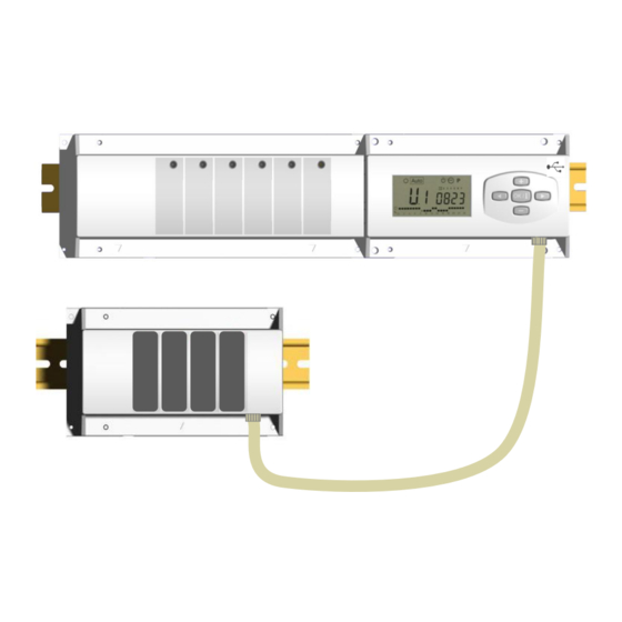
1. User Guide WFHC-MASTERH&C-BUS & SLAVE - Wired “BUS” connecting boxes specially designed to control your Water Floor Heating and cooling managed by actuators. - Work in combination with our BUS thermostat range (Digital and Basic) 2. Technical Characteristics Operating Temperature 0°C to 50°C Proportional Integral regulation. - Page 5 4. Small Description This controller (WFHC-MASTERH&C-BUS) used in combination with the WFHT-BASICH&C-BUS or WFHT-LCDH&C- BUS thermostat offers a complete package to manage all component of your water floor heating and cooling installation. You could control different type of installations like: Installation1: Heating only.
-
Page 6: Working Mode
6. Working mode Set CLOCK Menu: Use this menu to adjust the clock to the actual time. Use (+) & (-) to adjust minutes and Press (OK) Use (+) & (-) to adjust hours and Press (OK) Use (+) & (-) to adjust day and Press (OK) COMFORT operating mode: All the zones will follow indefinitely the Comfort temperature adjusted on each thermostat. - Page 7 PROGRAM menu: Use this menu to create or choose a program for each zone. By pressing (+) & (-) keys the zone number starts to blink, Use (◄) or (►) to see the others days in the program Zone number Program number Shows the daily program...
-
Page 8: Installation Menu
7. Installation menu First of all to enter in the parameters menu, go to the Comfort mode, press once and maintain the (Ok) key then press on the same time on the (◄) key. The following screen with the first parameter must appear: How to change a parameter value? Once the parameter is displayed, press the (OK) key to edit the value, then you can adjust it with (-) or (+) keys. - Page 9 rF: The Heating & Cooling mode will be done by the Master HC thermostat WFHT-BASICH&C-BUS. * Generally use when separate system is installed. (Boiler, water chillers...) CtAC: The Heating & Cooling mode will be done by the Heat Pump connected on the special input of your RF receiver (see the wiring for Type of the Heating &...
- Page 10 9. Thermostat initialization 1/ Standard thermostat initialisation: WFHT-BASIC-BUS or WFHT-LCD-BUS First of all to enter in the parameters menu, go to the Comfort mode, press once and maintain the (Ok) key then press on the same time on the (◄) key. The first parameter must be appears “F0 ProG”, you can now release the keys. By pressing several times on the (►) key, go to the “rF init”...
- Page 11 10. Special heat pump inputs wiring connection Humidity Input Heat & Cool Input (Check the “F8” and “F9” (Check the position of the parameters) “F7” parameters) NTC sensor 10k0 at 25°C (ß = 3950) WFH-SENSOR NTC sensor 10k0 at 25°C (ß = 3950) 1/ Humidity detection by NTC sensor: The NTC sensor is used to control the water temperature in the pipe.
- Page 12 11. Wiring assembly DIAGRAM Power Supply 230Vac 50Hz 4 actuators max per zone N PE L 220NC 220NC 220NC 220NC Chillers Boiler Humidity These 2 outputs can be used to control the Security contact heat pump Pump drier thermostat 230Vac 50Hz Check the voltage input of the heat Max 24 actuators pump before connections.
- Page 13 Wiring recommendation for “Bus” Connection WFHT-LCDH&C-BUS WFHT-LCD-BUS WFHT-BASICH&C-BUS or WFHT-BASIC-BUS - If the wiring distance between the thermostat and the WFHC- MODULE-BUS is more than 10 meters you must use a Shielded cable (Type “LiYCY” or equivalent, in this case the distance can be along up to 25M).
-
Page 14: Caractéristiques Techniques
1. Guide d’utilisation WFHC-MASTERH&C-BUS & SLAVE Boîte de connexion type « BUS » spécialement conçue pour la régulation des planchers chauffant et rafraîchissant hydrauliques gérés par électrovannes thermiques. 2. Caractéristiques techniques Température de fonctionnement 0°C to 50°C Régulation proportionnelle intégrale. Caractéristiques de régulation Ajustable dans le menu d‟installation Tension d’alimentation... -
Page 15: Présentation
4. Présentation Ce pack (WFHC-MASTERH&C-BUS) utilisé en combinaison avec le thermostat WFHT-BASICH&C-BUS ou WFHT- LCDH&C-BUS vous permettra de contrôler les différents composants (hydraulique ou électrique) de diverses installations de plancher chauffant et rafraîchissant à circulation d‟eau. Vous pourrez contrôler différents types d‟installation comme: Installation1: Chauffage uniquement Installation2: Climatisation uniquement Installation3: Pack E pour installation à... -
Page 16: Mode De Fonctionnement
6. Mode de fonctionnement Mode réglage de l’heure: Utilisez ce menu pour régler l‟horloge. Utilisez les touches (+) & (-) pour régler les minutes. Validez avec (OK) Utilisez les touches (+) & (-) pour régler les heures. Validez avec (OK) Utilisez les touches (+) &... -
Page 17: Création D'un Programme Utilisateur
Mode Programme: Utilisez ce menu pour créer et attribuer un programme à chaque zone. Choisissez tout d‟abord un numéro de zone avec les touches (+) & (-), Utilisez (◄) ou (►) pour accéder aux autres jours du programme. Numéro de programme Montre le programme de la journée Une fois le numéro de zone choisi (01 à... -
Page 18: Menu Installation
7. MENU INSTALLATION Tout d‟abord pour entrer dans le menu installation, placez vous sur le mode Confort à l‟aide des touches (◄) et (►). Maintenez ensuite la touche (OK) enfoncée, appuyez ensuite simultanément sur la touche (◄). L‟écran suivant avec le premier paramètre doit alors apparaître: Comment changer la valeur d’un paramètre? Une fois que le paramètre est affiché, appuyer sur la touche (OK) pour l‟éditer, ajustez le ensuite avec les touches (-) ou... - Page 19 rF: L‟ordre de fonctionnement Chaud / Froid sera donné par le WFHT- BASICH&C-BUS O WFHT-LCDH&C-BUS * Généralement utilisé dans les installations à éléments séparés. (Chaudière, groupe froid...) CtAC: L‟information du mode de fonctionnement Chaud / Froid sera donnée par le master en utilisant l‟entrée spécifique Chaud & Froid (Voir partie câblage Type de commutation pour plus…) Chaud/Froid...
-
Page 20: Initialisation Du Thermostat
9. INITIALISATION DU THERMOSTAT 1/ Initialisation standard du thermostat: WFHT-BASIC-BUS ou WFHT-LCD-BUS Tout d‟abord pour entrer dans le menu installation, placez-vous sur le mode Confort à l‟aide des touches (◄) et (►). Maintenez ensuite la touche (OK) enfoncée, appuyez ensuite simultanément sur la touche (◄). Le premier paramètre “F0 ProG”... -
Page 21: Entrées Spécifiques P.a.c
10. Entrées spécifiques P.A.C Connexion Entrée Chaud / Froid Entrée Humidité (Vérifier la postion du paramètre “F7”) (Vérfier les paramètres “F8” and “F9”) WFH-SENSOR NTC NTC sonde 10k0 at 25°C (ß = 3950) sonde 10k0 at 25°C (ß = 3950) 1/ Détection d’humidité... -
Page 22: Schéma De Câblage
11. Schéma de câblage Alimentation 230Vac 50Hz 4 électrovannes max par zone N PE L 220NC 220NC 220NC 220NC Climatiseur chaudière Déshumi- Ces 2 sorties peuvent être utilisées pour une Thermostat de dificateur commande de pompe à chaleur (PAC réversible) circulateur sécurité... - Page 23 Wiring recommendation for “Bus” Connection WFHT-LCDH&C-BUS WFHT-LCD-BUS WFHT-BASICH&C-BUS or WFHT-BASIC-BUS - Si la distance de câblage entre le module de connexion WFHC- MODULE-BUS et les thermostats est supérieure à 10M il faudra obligatoirement utiliser du câble blindé type “LiYCY” ou équivalent pour les connexions (dans ces conditions la distance pourra être augmentée jusqu‟à...
-
Page 24: Technische Eigenschappen
1. Handleiding WFHC-MASTERH&C-BUS & SLAVE - Bedrade “BUS”-aansluitingsdozen speciaal ontworpen voor het regelen van uw watervloerverwarming en –koeling beheerd door actuators. - Werk in combinatie met ons BUS-thermostatengamma (Digital en Basic) 2. Technische eigenschappen Werkingsbereik 0°C to 50°C Karakteristieken verschillende Integrale proportionele regeling.. -
Page 25: Presentatie
4. Presentatie Dit toestel (WFHC-MASTERH&C-BUS) gebruikt in combinatie met de thermostaat WFHT-BASICH&C-BUS o WFHT- LCDH&C-BUS vormt een compleet pakket dat toelaat alle componenten van uw vloerverwarming en koeling systeem te controleren. Verschillende installatie types kunnen gecontroleerd worden: Installatie 1: Enkel verwarmen. Installatie 2: Enkel koelen. - Page 26 6. Functie Modes Menu KLOKINSTELLING: Gebruik dit menu om de klok aan te passen aan de actuele tijd. Gebruik (+) & (-) om de minuten aan te passen en druk (OK) Gebruik (+) & (-) om het uur aan te passen en druk (OK) Gebruik (+) &...
- Page 27 Mode PROGRAMMA: Gebruik dit menu om een programma voor elke zone aan te maken of te kiezen. Druk op de (+) & (-) toetsen en het zone nummer begint te knipperen, Gebruik (◄) of (►) om de andere dagen in het programma te zien Zone nummer Programma...
- Page 28 7. Installatie Menu mode met behulp van de toetsen (◄) en (►) in het installateur menu, druk één maal Ga naar de Comfort blijvend op de (Ok) toets en druk vervolgens tegelijkertijd op de (◄) toets. Dit scherm met de eerste parameter verschijnt Hoe de waarde van de parameter aanpassen? Eenmaal de parameter wordt getoond, druk dan op de (OK) toets om te kunnen bewerken.
- Page 29 rF: De mode Verwarmen & Koelen wordt uitgevoerd door de Master HC thermostaat WFHT-BASICH&C-BUS O WFHT-LCDH&C-BUS. * Meestal van toepassing indien afzonderlijke systemen geïnstalleerd zijn (Boiler, waterkoelers...) . CtAC: De mode Verwarmen & Koelen wordt uitgevoerd door de Type omschakeling Warmtepomp die aangesloten is aan de speciale ingang van de RF Verwarmen (winter) &...
- Page 30 9. Configuratie thermostaat (Thermostaten aan de zones toewijzen) 1/ Standaard thermostaat initialisatie: WFHT-BASIC-BUS of WFHT-LCD-BUS mode met behulp van de toetsen (◄) en (►) in het installateur menu, druk één maal blijvend op Ga naar de Comfort de (OK) toets en druk vervolgens tegelijkertijd op de (◄) toets De eerste parameter die verschijnt is “F0 ProG”, nu kunnen de toetsen losgelaten worden.
- Page 31 10. Aansluitklemmen externe keuze van werkingsmode en Aansluitklemmen voorloopvoeler connectie NTC sensor 10k0 bij 25°C (ß = 3950) WFH-SENSOR NTC sensor 10k0 bij 25°C (ß = 3950) 1/ Vochtdetectie via NTC sensor: 1/ Heat & Cool detectie via sensor: (“F7” = SenS) De NTC sensor wordt gebruikt om de watertemperatuur in de leiding te controleren.
- Page 32 11. Aansluitschema Voeding 230Vac 50Hz 4 actuators max per zone N PE L 220NC 220NC 220NC 220NC Chillers Boiler Humidity Deze 2 outputs kunnen gebruikt worden om de Veiligheids contact warmtepomp te controleren. Pomp drier thermostaat 230Vac 50Hz Controleer de voeding van de Max 24 actuators warmtepomp vooraleer aan te sluiten.
- Page 33 Bedradingsaanbeveling voor “Bus”-aansluiting WFHT-LCDH&C-BUS WFHT-LCD-BUS WFHT-BASICH&C-BUS or WFHT-BASIC-BUS - Als de bedradingsafstand tussen de thermostaat en de WFHC- MODULE-BUS meer dan 10 meter bedraagt, moet u een Afgeschermde kabel gebruiken (Type “LiYCY” of gelijkwaardig, in dit geval kan de afstand maximum 25M bedragen). Als communicatieprobleem aanhoudt, de afgeschermde kabel proberen te verbinden met het minpunt “-“...
-
Page 34: Technische Daten
1. Bedienungsanleitung WFHC-MASTERH&C-BUS & SLAVE - Diese kabelgebundenen “BUS”-Anschlussdosen wurden speziell für die Steuerung Ihrer Wasser-Fußbodenheizung und –kühlung mit Stellantrieben entwickelt. - Arbeitet in Verbindung mit unserem Sortiment an BUS-Thermostaten (Digital und Basic) 2. Technische Daten Betriebstemperatur 0 °C bis 50 °C PI-Regelung Regelverhalten Einstellbar im Parameter-Menü... -
Page 35: Besondere Hinweise
4. Kurzbeschreibung Dieser Regelverteiler (WFHC-MASTERH&C-BUS) bietet bei kombinierter Nutzung mit dem Thermostat WFHT- BASICH&C-BUS oder WFHT-LCDH&C-BUS die Möglichkeit, alle Elemente Ihrer Wasser-Fußbodenheizung und - kühlung zentral zu regeln. Hiermit können unterschiedliche Anlagentypen geregelt werden, z. B.: Anlage 1: Nur Heizung. Anlage 2: Nur Kühlung. - Page 36 6. Betriebsart Uhrzeit-Menü: Mit diesem Menü kann die Uhrzeit eingestellt werden. Die Minuten mit (+) und (-) einstellen und (OK) drücken. Die Stunden mit (+) und (-) einstellen und (OK) drücken. Den Tag mit (+) und (-) einstellen und (OK) drücken. Komfortbetrieb: Alle Zonen werden auf unbestimmte Zeit auf die an dem jeweiligen Thermostat eingestellte Komforttemperatur geregelt.
- Page 37 Menü PROGRAMM: Mit diesem Menü können Sie für jede Zone ein Programm festlegen. Durch Drücken der Tasten (+) & (-) beginnt die Zonennummer zu blinken. Mit (◄) oder (►) zur Anzeige der anderen Tage im Programm wechseln Zonennummer Programmnummer Zeigt das Programm des Tages Wählen Sie einen Zonennummer 01 bis 12 und bestätigen Sie mit (OK): Nun können Sie für die jeweilige Zone ein Wochenprogramm auswählen.
- Page 38 7. Menü Anlagenparameter Um in das Anlagenparametermenü zu gelangen, wechseln Sie in den Komfortbetrieb, halten Sie die (OK)-Taste gedrückt und drücken Sie gleichzeitig (◄). Folgendes muss angezeigt werden (erster Parameter): Ändern eines Parameterwerts Wird der Parameter, den Sie ändern möchten, angezeigt, drücken Sie (OK): Sie können nun den Wert mit den Tasten (-) und (+) einstellen.
- Page 39 rF: Die Betriebsart Heizen/Kühlen wird vom Master-Thermostat WFHT-BASICH&C-BUS oder WFHT-LCDH&C-BUS bestimmt. * Wird allgemein bei Nutzung von getrennten Systemen (Kessel, Kaltwassersätze usw.) verwendet. CtAC: Die Betriebsart Heizen/Kühlen wird von der Wärmepumpe vorgegeben, die an einen Sondereingang an Ihrem Funkempfänger angeschlossen ist (Siehe Verkabelung für weitere Informationen). Umschalt-modi von Heizen &...
- Page 40 9. Thermostat-Initialisierung ( Zonenzuweisung für Thermostate 1/ Initialisierung des Standardthermostats: WFHT-BASIC-BUS bzw. WFHT-LCD-BUS Um in das Anlagenparameter-Menü zu gelangen, wechseln Sie in den Komfortbetrieb , halten Sie die (OK)-Taste gedrückt und betätigen Sie zeitgleich die Taste (◄). Als erster Parameter muss „F0 ProG“ erscheinen; Sie können nun die Tasten loslassen.
- Page 41 10. Verkabelung der Wärmepumpe Connection Eingang Feuchtigkeit Eingänge Heiß & Kalt (Parameter “F8” und “F9” (Position des Parameters “F7” überprüfen) überprüfen) NTC-Sensor 10k0 bei 25°C (ß = 3950) WFH-SENSOR NTC Sensor 10k0 bei 25°C (ß = 3950) 1/ Feuchtigkeitserkennung über NTC-Sensor: 1/ Heiz/Kalt-Erkennung über Sensor: („F7”...
- Page 42 11. Schaltplan Betriebsspannung 230 V AC 50Hz max. 4 Stellantriebe pro Zone N PE L 220NC 220NC 220NC 220NC Kühler Kessel Ent- Diese beiden Ausgänge können zur Ansteuerung Sicherheits- der Wärmepumpe verwendet werden feuchter Pumpe thermostat 230Vac 50Hz Die Eingangsspannung der Max.
- Page 43 Empfehlungen für die Verkabelung für den “Bus”-Anschluss WFHT-LCDH&C-BUS oder WFHT-LCD-BUS WFHT-BASICH&C-BUS oder WFHT-BASIC-BUS - Wenn der Abstand zwischen dem Thermostat und dem WFH- MODULE-BUS mehr als 10 Meter beträgt, müssen Sie ein Abgeschirmtes Kabel benutzen (Typ “LiYCY” oder ein vergleichbares Kabel, in diesem Fall kann der Abstand bis zu 25 Meter betragen).
-
Page 44: Caratteristiche Tecniche
1. Manuale d’uso WFHC-MASTERH&C-BUS & SLAVE - Scatole di connessione del “BUS” cablato appositamente progettate per controllare impianti di riscaldamento e raffreddamento a pavimento a circolazione idraulica gestiti da elettrovalvole. - Funziona in combinazione con la serie di termostati BUS (digitali e di base). 2. -
Page 45: Display E Comandi
4. Presentazione Il pack (WFHC-MASTERH&C-BUS) utilizzato unitamente al termostato WFHT-BASICH&C-BUS o WFHT-LCDH&C-BUS vi permetterà di controllare le diverse componenti (idrauliche o elettriche) di diversi impianti di riscaldamento e raffreddamento a pavimento a circolazione idraulica. Potrete controllare istallazioni di diverso tipo come: Installazione1: Solo riscaldamento Installazione 2: Solo climatizzazione Installazione 3: Pack E per installazione a elementi separati (Caldaia e climatizzazione) o pompa di calore classica... -
Page 46: Modo Di Funzionamento
6. Modo di funzionamento Impostazione dell'ora: Utilizzare questo menu per regolare l'ora. Utilizzare i tasti (+) e (-) per regolare i minuti. Per convalidare: (OK) Utilizzare i tasti (+) e (-) per regolare le ore. Per convalidare: (OK) Utilizzare i tasti (+) e (-) per regolare il giorno. Per convalidare: (OK) Modo COMFORT: Tutte le zone seguiranno l'impostazione di temperatura regolata sul rispettivo termostato. - Page 47 Modo Programmazione: Utilizzare questo menu per creare e attribuire un programma a ciascuna zona. Per prima cosa selezionare un numero di zona con i tasti (+) e (-), Utilizzare (◄) o (►) per accedere agli altri giorni del programma. Numero di programma Visualizza il programma della giornata Una volta scelto il numero (da 01 a 12), premere su (OK) per accedere alla selezione del numero di programma.
-
Page 48: Menu Installazione
7. MENU INSTALLAZIONE servendosi dei tasti (◄) e (►). Mantenere quindi il Per entrare nel menu installazione, posizionarsi sul modo Comfort tasto (OK) premuto e premere simultaneamente sul tasto (◄). Dovrebbe apparire la schermata successiva con il primo parametro: Come modificare il valore di un parametro Una volta visualizzato il parametro, premere sul tasto (OK) per modificarlo, quindi impostarlo mediante i tasti (-) o (+). - Page 49 rF: L‟ordine di funzionamento Caldo/Freddo sarà dato dal termostato WFHT-BASICH&C-BUS e WFHT-LCDH&C-BUS. * Generalmente utilizzato negli impianti a elementi separati. (Caldaia, climatizzazione...) CtAC: L‟informazione sul modo di funzionamento Caldo / Freddo sarà data dal master utilizzando l'ingresso specifico Caldo e Freddo (Vedi Tipo di commut/ Caldo sezione cablaggio per maggiori spiegazioni) (inverno) e Freddo (estate)
- Page 50 9. Inizializzazione (Assign Thermostats to zones) 1/ Inizializzazione termostato standard: WFHT-BASIC-BUS o WFHT-LCD-BUS servendosi dei tasti (◄) e (►). Mantenere quindi il Per entrare nel menu installazione, posizionarsi sul modo Comfort tasto (OK) premuto e premere simultaneamente sul tasto (◄). Il primo parametro “F0 ProG” dovrebbe apparire. Spostarsi nel menu mediante il tasto (►), una volta visualizzato il parametro “rF init”...
- Page 51 10. Input specifici pompa di calore Connessione Ingresso Caldo/Freddo Ingresso Umidità (Verificare la posizione del (Verificare i parametri parametro “F7”) “F8” e “F9”) WFH-SENSOR NTC WFH-SENSOR NTC sonda 10k0 sonda 10k0 a 25°C (ß = 3950) a 25°C (ß = 3950) 1/ Rilevazione umidità...
-
Page 52: Schema Di Cablaggio
11. Schema di cablaggio Alimentazione 230Vac 50Hz 4 elettrovalvole massimo per zona N PE L UFH- UFH- UFH- UFH- ACT230NCx ACT230NCx ACT230NCx ACT230NCx Climatizzatore Caldaia Deumidifica Termostato di Queste due uscite possono essere utilizzate Circolatore tore sicurezza per un ordine alla pompa di calore (PDC 230Vac 50Hz reversibile) Max 24 elettrovalvole... - Page 53 Raccomandazioni di cablaggio per collegamento WFHT-LCDH&C-BUS WFHT-LCD-BUS WFHT-BASICH&C-BUS WFHT-BASIC-BUS “Bus” - Se la distanza di cablaggio tra il termostato e WFHC-MODULE- BUS supera 10 metri, si deve usare un cavo schermato (tipo “LiYCY” o equivalente, in tal caso la distanza può arrivare a 25M). Se il problema di comunicazione persiste, provare a collegare il cavo schermato con il punto meno “-”...
- Page 56 www.wattsindustries.com PPLIMP09825Aa rev: 18/11/2010...