Table des Matières
Publicité
Les langues disponibles
Les langues disponibles
Liens rapides
Bedienungsanleitung
Labornetzgeräte-Serie VLP-USB
Best.-Nr. 1629369
Best.-Nr. 1629370
Best.-Nr. 1629371
Best.-Nr. 1629372
Operating instructions
Laboratory power supply series VLP-USB
Item No. 1629369
Item No. 1629370
Item No. 1629371
Item No. 1629372
Mode d'emploi
Alimentations de laboratoire série VLP-USB
N° de commande 1629369
N° de commande 1629370
N° de commande 1629371
N° de commande 1629372
Gebruiksaanwijzing
Laboratoriumnetvoedingen serie VLP-USB
Bestelnr. 1629369
Bestelnr. 1629370
Bestelnr. 1629371
Bestelnr. 1629372
VLP 1303 USB
VLP 1405 USB
VLP 1602 USB
VLP 2403 USB
VLP 1303 USB
VLP 1405 USB
VLP 1602 USB
VLP 2403 USB
VLP 1303 USB
VLP 1405 USB
VLP 1602 USB
VLP 2403 USB
VLP 1303 USB
VLP 1405 USB
VLP 1602 USB
VLP 2403 USB
Seite 2 - 29
Page 30 - 55
Page 56 - 82
Pagina 83 - 109
Publicité
Chapitres
Table des Matières
Dépannage

Manuels Connexes pour VOLTCRAFT VLP-USB Série


Sommaire des Matières pour VOLTCRAFT VLP-USB Série
- Page 1 Bedienungsanleitung Labornetzgeräte-Serie VLP-USB Best.-Nr. 1629369 VLP 1303 USB Best.-Nr. 1629370 VLP 1405 USB Best.-Nr. 1629371 VLP 1602 USB Best.-Nr. 1629372 VLP 2403 USB Seite 2 - 29 Operating instructions Laboratory power supply series VLP-USB Item No. 1629369 VLP 1303 USB Item No.
-
Page 2: Table Des Matières
Inhaltsverzeichnis Seite Einführung ................................3 Lieferumfang ................................3 Symbol-Erklärung ..............................4 Sicherheitshinweise .............................5 VLP 1303 USB // VLP 1405 USB // VLP 1602 USB ...................6 5.1. Bestimmungsgemäße Verwendung ......................6 5.2. Bedienelemente ............................8 5.2.1. Symbolerklärung ..........................9 5.3. Funktionsbeschreibung ..........................10 5.4. Inbetriebnahme ............................10 5.4.1. Aufstellen des Gerätes ........................10 5.4.2. -
Page 3: Einführung
Aufgaben gerecht. Voltcraft bietet Ihnen zuverlässige Technologie zu einem außergewöhnlich günstigen Preis-/Leis- ® tungsverhältnis. Wir sind uns sicher: Ihr Start mit Voltcraft ist zugleich der Beginn einer langen und guten Zusammenarbeit. Viel Spaß mit Ihrem neuen Voltcraft -Produkt! ® Bei technischen Fragen wenden Sie sich bitte an: Deutschland: www.conrad.de/kontakt... -
Page 4: Symbol-Erklärung
3. Symbol-Erklärung Das Symbol mit dem Blitz im Dreieck wird verwendet, wenn Gefahr für Ihre Gesundheit besteht, z.B. durch einen elektrischen Schlag. Das Symbol mit dem Ausrufezeichen im Dreieck weist auf wichtige Hinweise in dieser Bedie- nungsanleitung hin, die unbedingt zu beachten sind. Das Pfeil-Symbol ist zu finden, wenn Ihnen besondere Tipps und Hinweise zur Bedienung gege- ben werden sollen. -
Page 5: Sicherheitshinweise
4. Sicherheitshinweise Lesen Sie bitte vor Inbetriebnahme die komplette Anleitung durch, sie enthält wichtige Hinweise zum korrekten Betrieb. Bei Schäden, die durch Nichtbeachten dieser Bedienungsanleitung verursacht werden, erlischt die Gewährleistung/Garantie! Für Folgeschäden übernehmen wir keine Haftung! Bei Sach- oder Personenschäden, die durch unsachgemäße Handhabung oder Nichtbeachten der Sicherheitshinweise verursacht werden, übernehmen wir keine Haftung! In solchen Fällen erlischt die Gewährleistung/Garantie. -
Page 6: Vlp 1303 Usb // Vlp 1405 Usb // Vlp 1602 Usb
• Das Netzgerät ist nicht für die Anwendung an Menschen und Tieren zugelassen. • Setzen Sie das Gerät keinen mechanischen Beanspruchungen aus. Bereits der Fall aus geringer Höhe kann das Gerät beschädigen. Vibrationen und direktes Sonnenlicht sind zu vermeiden. • Stellen Sie keine mit Flüssigkeit gefüllten Gefäße auf dem Gerät ab. •... - Page 7 VLP 1602 USB 0 - 60 V/DC 4,0 - 6,2 V/DC 5 V/DC, max. 2,5 A 0,01 - 1,5 A 0 - 2,5 A 9 V/DC, max. 2,0 A 12 V/DC, max. 1,5 A • Spannung und Stromstärke ist bei Ausgang A und Ausgang B1-USB stufenlos regelbar. Die Spannungs- und Stromanzeige von Ausgang B1-USB erfolgt per Tastendruck über die Anzeige von Ausgang A.
-
Page 8: Bedienelemente
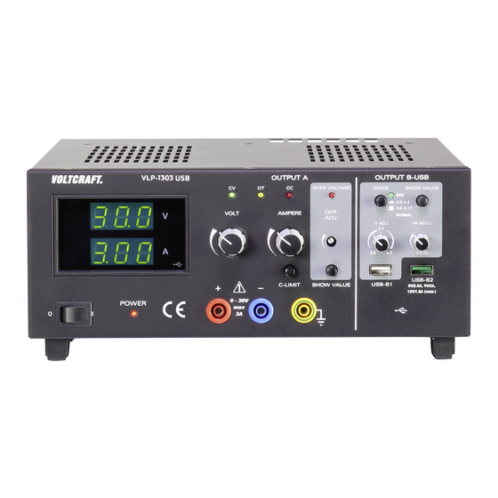
5.2. Bedienelemente 1 Netzschalter zur Inbetriebnahme (I = Ein / 0 = Aus) 2 Anzeige Strom (A) 3 Anzeige Spannung (V) 4 Spannungseinstellregler für Ausgang A (VOLT) 5 Statusanzeige Ausgang A (CV = Konstantspannung) 6 Statusanzeige Ausgang A (OT = Übertemperatur) 7 Statusanzeige Ausgang A (CC = Konstantstrom) 8 Stromeinstellregler für Ausgang A (AMPERE) 9 Statusanzeige bei aktivierter Überspannungsabschaltung (OVER VOLTAGE) -
Page 9: Symbolerklärung
12 Taste zur Anzeige der Spannungs- und Stromeinstellung von Ausgang USB-B1 13 Spannungseinstellregler für Ausgang B USB-B1 (V ADJ.) 14 Stromeinstellregler für Ausgang B USB-B1 (A ADJ.) 15 Prozessorgesteuerter USB-Ausgang B USB-B2 16 Regelbarer USB-Ausgang B USB-B1 17 Einstellregler für den Pegel zur Überspannungsabschaltung (OVP ADJ.) 18 Taste zur Anzeige des eingestellten Pegels zur Überspannungsabschaltung 19 Anschlussbuchse „Erdpotential“... -
Page 10: Funktionsbeschreibung
5.3. Funktionsbeschreibung Das Labornetzgerät arbeitet mit zuverlässiger und robuster Lineartechnologie. Dies ermöglicht eine stabile Aus- gangsspannung und geringste Störspannungen. Die Gleichspannungsausgänge sind potentialfrei und weisen eine Schutztrennung gegenüber der Netzspannung auf. Sekundärseitig erfolgt der DC-Anschluss jeweils über zwei farbige Sicherheits-Buchsen bzw. zwei USB-Buchsen Typ A. Im übersichtlichen Display erfolgt die Spannungs- und Stromanzeige für den Ausgang A (V = Volt = Einheit der elek- trischen Spannung, A = Ampere = Einheit der elektrischen Stromstärke). -
Page 11: Ausgangsspannung Von Ausgang A Einstellen
5.4.3. Ausgangsspannung von Ausgang A einstellen • Entfernen Sie angeschlossene Verbraucher von Ausgang A (20 und 21). • Schalten Sie das Netzgerät über den Betriebsschalter (1) ein. Die Betriebsanzeige (24) leuchtet und im Display erscheint die Spannungs- und Stromanzeige. • Stellen Sie den Stromeinstellregler „AMPERE“ (8) in Mittelstellung. •... -
Page 12: Ausgangsspannung Und Strom Von Ausgang B Usb-B1 Einstellen
• Stellen Sie mit einem passenden Schlitzschraubendreher den gewünschten max. Spannungspegel am Einstell- regler „OVP ADJ.“ (17) ein. Wünschen Sie keine Schutzabschaltung, so drehen Sie den Einstellregler auf den rechten Endanschlag. • Lassen Sie die Taste „SHOW VALUE“ (18) los. Der Überspannungsschutz ist aktiviert. Ausgang OUTPUT A zurücksetzen Sobald über den Einstellregler „VOLT“... -
Page 13: Ausgang B Usb-B2
5.4.7. Ausgang B USB-B2 Der Ausgang B USB-B2 ist prozessorgesteuert und nicht regelbar. Dieser Ausgang erkennt die Parameter des ange- schlossenen Endgerätes und stellt automatisch die bestmögliche Einstellung für Spannung und Strom ein. Eine Anzeige der vorhandenen Parameter ist nicht möglich. 5.5. -
Page 14: Technische Daten
5.6. Technische Daten VLP 1303 USB VLP 1405 USB VLP 1602 USB Ausgangsleistung 123 W 233 W 123 W Ausgangsspannung Ausgang A 0 - 30 V/DC 0 - 40 V/DC 0 - 60 V/DC Ausgangsstrom Ausgang A 0,01 - 3 A 0,01 - 5 A 0,01 - 1,5 A Genauigkeit V-Anzeige... -
Page 15: Vlp 2403 Usb
6. VLP 2403 USB 6.1. Bestimmungsgemäße Verwendung Das Labornetzgerät dient als potentialfreie DC-Spannungsquelle zum Betrieb von Kleinspannungsverbrauchern. Es stehen vier voneinander unabhängige Ausgänge zur Verfügung. Zwei regelbare Laborausgänge, ein regelbarer USB- Ausgang und ein prozessorgesteuerter USB-Ausgang. Die beiden regelbaren Laborausgänge können über einen Modus-Wahlschalter in vier verschiedenen Betriebsarten betrieben werden. -
Page 16: Funktionsbeschreibung
• Die Strombegrenzung für den Konstantstrombetrieb bei Ausgang A und C kann per Tastendruck voreingestellt werden. Eine Kurzschlussbrücke am Ausgang ist während der Einstellung nicht nötig. • Für die Ausgänge A und C kann zur Sicherheit eine Spannungsbegrenzung (OVP) eingestellt werden. Dies kann für die beiden Ausgänge unabhängig voneinander erfolgen. -
Page 17: Bedienelemente
6.3. Bedienelemente 1 Netzschalter zur Inbetriebnahme (I = Ein / 0 = Aus) 2 Anzeige Strom (A) für Ausgang OUTPUT A 3 Anzeige Spannung (V) für Ausgang OUTPUT A 4 Spannungseinstellregler (VOLT) für Ausgang A 5 Statusanzeige Ausgang A (CV = Konstantspannung) 6 Statusanzeige Ausgang A (OT = Übertemperatur) 7 Statusanzeige Ausgang A (CC = Konstantstrom) 8 Stromeinstellregler (AMPERE) für Ausgang A... -
Page 18: Symbolerklärung
17 Statusanzeige Ausgang C (OT = Übertemperatur) 18 Statusanzeige Ausgang C (CC = Konstantstrom) 19 Stromeinstellregler (AMPERE) für Ausgang C 20 Statusanzeige bei aktivierter Überspannungsabschaltung (OVER VOLTAGE) für Ausgang C 21 Anzeige Spannung (V) für Ausgang C 22 Anzeige Strom (A) für Ausgang C 23 USB-Symbol signalisiert die Anzeige von Ausgang B USB-B1 24 Gerätefüße an der Vorderseite aufklappbar 25 Anschlussbuchse „Erdpotential“... -
Page 19: Inbetriebnahme
6.4. Inbetriebnahme Das Labornetzgerät ist kein Ladegerät. Verwenden Sie zum Laden von Akkus geeignete Ladegeräte mit entsprechender Ladeabschaltung. Bei längerem Betrieb mit Nennlast wird die Gehäuseoberfläche warm. Achtung! Mögliche Verbren- nungsgefahr ! Achten Sie daher unbedingt auf eine ausreichende Belüftung des Netzgerätes und betreiben Sie es niemals teilweise oder ganz abgedeckt, um eventuelle Schäden zu vermeiden. -
Page 20: Individual-Betrieb (Ind)
Um die Betriebsart zu Wählen, drehen Sie den Drehschalter „MODE“ (32) in die entsprechende Position. Achten Sie vor der Umstellung der Funktion, dass kein Verbraucher an den beiden Ausgängen A und C angeschlossen sind. Diese könnten im ungünstigen Fall durch Überspannung beschädigt werden. 6.4.4. -
Page 21: Parallel-Betrieb (Par)
• Schließen Sie den Verbraucher an Ausgang A (36 und 37) oder Ausgang C (28 und 29) an und schalten Sie ihn ein. Achten Sie auf die Polarität. Die LED-Anzeige „CC“ (7 bzw. 18) leuchtet, sobald der eingestellte Strompegel überschritten wird und die Strombe- grenzung aktiv ist. -
Page 22: Ausgangsspannung Einstellen
Ausgangsspannung einstellen • Wählen Sie am Drehschalter„MODE (32) die Betriebsart „PAR“. • Stellen Sie die beiden Stromeinstellregler „AMPERE“ (8 bzw. 19) in Mittelstellung. • Über den Drehregler „VOLT“ (4 bzw. 15) kann die Ausgangsspannung eingestellt werden. Drehen Sie im unteren Spannungsbereich bis ca. -
Page 23: Serien-Betrieb (Ser)
6.4.6. Serien-Betrieb (SER) Die beiden Laborausgänge (OUTPUT A und C) werden intern in Reihe (in Serie) zusammengeschaltet. Durch die Serienschaltung wird die Ausgangsspannung der beiden Ausgänge addiert. Die max. Ausgangsspannung beträgt in diesem Modus max. 80 V/DC. Der Ausgangsstrom beträgt max. 3 A. Durch die interne Beschaltung ist es möglich die max. -
Page 24: Tracking-Betrieb (Trck)
• Schließen Sie den Verbraucher an den Ausgangsbuchsen „+“ von Ausgang A (37) und „-„ von Ausgang C (28) an und schalten Sie ihn ein. Achten Sie auf die Polarität. Die Ausgangsspannungen der beiden Ausgänge addieren sich und werden am Ausgang gebündelt. Die LED-Anzeige „CC“... -
Page 25: Usb-Ausgang
• Drücken Sie die Taste „C-LIMIT“ (30 bzw. 38) und halten Sie diese Taste während des Einstellvorganges gedrückt. Der entsprechende Ausgang wird automatisch abgeschaltet, solange die Taste „C-LIMIT“ gedrückt wird. Die Span- nungsanzeige geht deshalb auf ca. 0 zurück. • Über den Drehregler „AMPERE“ (8 bzw. 19) kann die max. Stromstärke (Strombegrenzung) eingestellt werden. Lassen Sie nach erfolgter Einstellung die Taste „C-LIMIT“... -
Page 26: Technische Daten
Schließen Sie den Verbraucher an Ausgang B USB-B1 (33) an und schalten Sie ihn ein. Achten Sie auf die Polarität. Der maximale Stromwert beträgt 2,5 A, eine Strombegrenzung löst bei Überschreitung dieser Ausgänge automatisch aus. Die USB-Buchse ist standardmäßig beschaltet. Die Skizze zeigt die Kontaktierung. Die entsprechenden Spannungs- und Stromwerte können jederzeit durch Drücken der Taste „SHOW VA- LUE“... -
Page 27: Entsorgung
Schutzklasse Netzanschluss Kaltgeräte-Einbaustecker, IEC 320 C14 Gewicht 11,0 kg Abmessungen (B x H x T) 440 x 125 x 270 mm 7. Entsorgung Elektronische Altgeräte sind Wertstoffe und gehören nicht in den Hausmüll. Entsorgen Sie das Produkt am Ende seiner Lebensdauer gemäß den geltenden gesetzlichen Bestimmungen. 8. -
Page 28: Behebung Von Störungen
9. Behebung von Störungen Mit dem Labornetzgerät haben Sie ein Produkt erworben, welches zuverlässig und betriebssicher ist. Dennoch kann es zu Problemen oder Störungen kommen. Hier möchten wir Ihnen beschreiben, wie Sie mögliche Störungen leicht selbst beheben können: Beachten Sie unbedingt die Sicherheitshinweise! Überprüfen Sie regelmäßig die technische Sicherheit des Gerätes z.B. - Page 29 VLP 1303 USB // VLP 1405 USB // VLP1602 USB Die Anzeige „OVER VOLTAGE“ Der voreingestellte Pegel für den Überspannungsschutz wurde überschritten. leuchtet. Der Ausgang OUTPUT A wurde abgeschaltet. Setzen Sie das Gerät wie im Kapitel „Ausgang OUTPUT A zurücksetzen“ auf Seite 12 beschrieben zurück.
- Page 30 Table of contents Page Introduction ................................31 Delivery content ..............................31 Explanation of symbols ............................32 Safety information ..............................32 VLP 1303 USB // VLP 1405 USB // VLP 1602 USB ..................34 5.1. Intended use ..............................34 5.2. Product overview ............................35 5.2.1. Explanation of symbols ........................36 5.3.
-
Page 31: Introduction
Voltcraft offers you reliable technology at an extraordinarily favourable cost-performance ratio. ® We are confident that starting to use Voltcraft will also be the beginning of a long, successful relationship. ® We hope you enjoy your new Voltcraft product! ®... -
Page 32: Explanation Of Symbols
3. Explanation of symbols The symbol with the lightning in a triangle indicates that there is a risk to your health, e.g. due to an electric shock. The symbol with an exclamation mark in a triangle is used to highlight important information in these operating instructions. - Page 33 • Please make sure that your hands, your shoes, your clothing, the floor and the power supply are dry. • Maintenance, adjustment or repair work may only be carried out by an expert/authorised service centre, who/which is familiar with the hazards involved and the relevant regulations. •...
-
Page 34: Vlp 1303 Usb // Vlp 1405 Usb // Vlp 1602 Usb
5. VLP 1303 USB // VLP 1405 USB // VLP 1602 USB 5.1. Intended use • The laboratory power supply unit serves as a potential-free DC voltage source to operate low-voltage consumers. It has three independent outputs. An adjustable laboratory output, an adjustable USB output and a processor- controlled USB output. -
Page 35: Product Overview
• Using this product for any purpose other than those described above may damage the product and result in a short- circuit, fire or electric shock. The product must not be modified or reassembled! • Always observe the safety information in these instructions. 5.2. -
Page 36: Explanation Of Symbols
6 Output A status display (OT = overtemperature) 7 Output A status display (CC = constant current) 8 Current adjuster for output A (AMPERE) 9 Status display when overvoltage cut-off active (OVER VOLTAGE) 10 Push switch for voltage range selection of output B USB-B1 11 Flashing status display while the push button (10) pressed in 12 Button for displaying the voltage and current of output USB-B1 13 Voltage adjuster for output B USB-B1 (V ADJ.) -
Page 37: Functional Description
5.3. Functional description The laboratory power supply works with reliable and solid linear technology. This ensures a stable output voltage and the lowest interference voltages. The DC output voltages are isolated and feature protective isolation against the mains voltage. Secondarily, the DC connection is effected via two coloured safety sockets or two USB sockets type A. The concise display show the voltage and current for output A (V = Volt = unit of electrical voltage, A = Ampere = unit of electrical current). -
Page 38: Setting The Output Voltage Of Output A
5.4.3. Setting the output voltage of output A • Disconnect devices connected to output A (20 and 21). • Switch the power supply on at the power switch (1). The operating display (24) lights up and the current and voltage display appear on the display. -
Page 39: Setting The Output Voltage And Current Of Output B Usb-B1
Resetting OUTPUT A As soon as the safety level set with the “VOLT” adjuster (4) has been exceeded, “OUTPUT A” switches off immedi- ately. The voltage display (3) returns to approx. 0 V and the “OVER VOLTAGE” status display (9) lights up red. •... -
Page 40: Output B Usb-B2
5.4.7. Output B USB-B2 Output B USB-B2 is processor-controlled and is not adjustable. This output identifies the parameters of the connected terminal device and automatically sets the best possible settings for voltage and current. Display of the current parameters is not possible. 5.5. -
Page 41: Technical Specifications
5.6. Technical specifications VLP 1303 USB VLP 1405 USB VLP 1602 USB Output power 123 W 233 W 123 W Output A output voltage 0 - 30 V/DC 0 - 40 V/DC 0 - 60 V/DC Output A output current 0.01 - 3 A 0.01 - 5 A 0.01 - 1.5 A... -
Page 42: Vlp 2403 Usb
6. VLP 2403 USB 6.1. Intended use The laboratory power supply unit serves as a potential-free DC voltage source to operate low-voltage consumers. It has four independent outputs. Two adjustable laboratory outputs, an adjustable USB output and a processor- controlled USB output. The two adjustable laboratory outputs can be operated via a mode selector switch in four different operating modes. -
Page 43: Product Overview
• The current limitation for constant current mode can be preset at output A and C with the push of a button. A short- circuit jumper at the output is not required during setting. • For output A and C, a voltage limitation (OVP) can be set for safety purposes. This can be set independently for the two outputs. - Page 44 1 Power switch for putting the device into operation (I=ON/0=OFF) 2 Current display (A) for OUTPUT A 3 Voltage display (V) for OUTPUT A 4 Voltage adjuster (VOLT) for output A 5 Output A status display (CV = constant voltage) 6 Output A status display (OT = overtemperature) 7 Output A status display (CC = constant current) 8 Current adjuster (AMPERE) for output A...
-
Page 45: Explanation Of Symbols
37 Positive of output A connection socket 38 “C-LIMIT” button for displaying and setting the current limitation of output A 39 Power indicator when the device is switched on 40 Rear heat sink 41 Fuse holder for the mains fuse 42 Earthed low-power connection for mains cable 6.2.1. -
Page 46: Setting Up The Device
If your power supply is not required, disconnect it from the mains. The maximum current consumption of the device to be connected must not exceed the capacity indicated in the technical specifications. When switching the outputs or several power supplies in series, voltages of >70 V/DC may be gen- erated, which may be fatal if touched. - Page 47 Setting the output voltage of output A and C • Disconnect consumers connected to output A (36 and 37) and output C (28 and 29). • Set the current adjuster for the respective output “AMPERE” (8 or 19) to the centre position. •...
-
Page 48: Parallel Operation (Par)
• With the laboratory power supply switched on, press and hold the “SHOW VALUE” button (34 or 27) during setting. • The display (3 or 21) shows the current voltage level. • Use an appropriate slotted screwdriver to set the desired max. voltage level on the “OVP ADJ.” (35 or 26) adjuster. If you do not want a protective cut-off, turn the adjuster all the way to the right. -
Page 49: Series Operation (Ser)
• The voltage value “V” is displayed on the display (3 or 21). The two voltage displays (3 and 21) show the same voltage at the output and may not be added together. In normal mode, the device operates in constant voltage mode. This means that the power supply emits a constant, preset output voltage. -
Page 50: Tracking Mode (Trck)
• Use the “VOLT” rotary control (4 or 15) to set the output voltage. Note that the two set voltages at the output are added together. • The voltage values “V” are shown on the display (3 and 21) and must be added together. The sum of the voltage setting is output at both output sockets (37 and 28). -
Page 51: Usb Output
• The output voltage for both outputs can be set with the “VOLT” rotary control (4) of output A. • The voltage value “V” is displayed on the display (3 or 21). In normal mode, the device operates in constant voltage mode. This means that the power supply emits a constant, preset output voltage. -
Page 52: Technical Data
• You can set the output voltage for output B USB-B1 with the “V ADJ.” rotary control (10). • You can adjust the current limitation for output B USB-B1 with the “A ADJ.” rotary control (13) ensure the current value is high enough to not cutoff the voltage. •... -
Page 53: Disposal
A display accuracy ≤±(2% + 0.02 A) Operating voltage 230 V/AC (±10%) 50 Hz Power consumption (max.) 590 VA Slow-blow mains fuse (5x 20 mm) T3, 15 A/250 V Operating temperature +5 to +40 °C Rel. humidity max. 85%, non-condensing Protection class Mains connection Low-power device installation socket, IEC 320 C14... -
Page 54: Troubleshooting
9. Troubleshooting By purchasing the laboratory power supply unit, you have acquired a product that is reliable and operationally safe. However, problems and malfunctions may still occur. This section explains how to troubleshoot common issues: Always observe the safety information in these instructions. Regularly check the technical safety of the device e.g. - Page 55 VLP 2403 USB The “OVER VOLTAGE” display lights The preset level for overvoltage protection has been exceeded. OUT- PUT A or OUTPUT C was switched off. Reset the device as outlined in chapter “Setting the overvoltage protec- tion (OVP) and resetting the device” on page 47. The “OVER VOLTAGE”...
- Page 56 Sommaire Page Introduction ................................57 Contenu ................................57 Explication des symboles ..........................58 Consignes de sécurité ............................59 VLP 1303 USB // VLP 1405 USB // VLP 1602 USB ..................61 5.1. Utilisation prévue ............................61 5.2. Éléments de fonctionnement ........................62 5.2.1. Explications des symboles ......................63 5.3.
-
Page 57: Introduction
à un rapport qualité-prix particulièrement avantageux. ® Nous en sommes convaincus : votre premier contact avec Voltcraft marque le début d’une coopération efficace de longue durée. Nous vous souhaitons beaucoup de plaisir avec votre nouveau produit Voltcraft ®... -
Page 58: Explication Des Symboles
3. Explication des symboles Le symbole d’éclair dans un triangle indique un risque pour votre santé, par ex. suite à un choc électrique. Le symbole du point d’exclamation dans un triangle a pour but d’attirer votre attention sur des consignes importantes du mode d’emploi qui doivent impérativement être respectées. Le symbole de la flèche précède les conseils et remarques spécifiques à... -
Page 59: Consignes De Sécurité
4. Consignes de sécurité Veuillez lire entièrement ce mode d’emploi avant la mise en service ; il contient des instructions importantes relatives au bon fonctionnement du produit. Tout dommage résultant d’un non-respect du présent manuel d’utilisation entraîne l’annulation de la garantie ! Nous déclinons toute responsabilité pour les dommages consécutifs ! Nous déclinons toute responsabilité... - Page 60 • N’employez que les fusibles du type et de l’intensité du courant nominal spécifiés. L’utilisation de fusibles pontés est strictement interdite. • Éviter l’utilisation de câbles métalliques dénudés. • Il est interdit de porter tout bijou métallique ou conducteur tels que chaînes, bracelets, bagues ou simi- laires quand vous utilisez l’alimentation.
-
Page 61: Vlp 1303 Usb // Vlp 1405 Usb // Vlp 1602 Usb
5. VLP 1303 USB // VLP 1405 USB // VLP 1602 USB 5.1. Utilisation prévue • Le bloc d’alimentation de laboratoire sert de source de tension CC sans potentiel pour faire fonctionner des appareils électriques basse tension. Trois sorties indépendantes sont disponibles. Une sortie laboratoire réglable, une sortie USB réglable et une sortie USB commandée par microprocesseur. -
Page 62: Éléments De Fonctionnement
• Le fonctionnement dans des environnements à forte teneur en poussière, gaz, vapeurs ou solvants inflammables n’est pas autorisé. Il existe un risque d’explosion et d’incendie ! • Toute autre utilisation que celle décrite entraîne des dommages au produit et présente de plus des risques tels que court-circuit, incendie, électrocution, etc. -
Page 63: Explications Des Symboles
6 Indicateur d’état de la sortie A (OT = surchauffe) 7 Indicateur d’état de la sortie A (CC = courant constant) 8 Bouton de réglage du courant de la sortie A (AMPERE) 9 Indicateur d’état lors de coupure automatique en cas de surtension (OVER VOLTAGE) 10 Commutateur de sélection de plage de la tension de la sortie B USB-B1 11 Indicateur d’état clignotant en cas de commutateur enfoncé... -
Page 64: Description Du Fonctionnement
5.3. Description du fonctionnement L’alimentation de laboratoire emploie une technologie linéaire fiable et robuste. Cela permet une tension de sortie stable et de faibles tensions parasites. Les sorties à tension continue sont sans potentiel et présentent une sépara- tion de protection par rapport à la tension de réseau. Le raccordement secondaire CC s’effectue au moyen de deux douilles de sécurité... -
Page 65: Réglage De La Tension De La Sortie A
5.4.3. Réglage de la tension de la sortie A • Retirez les consommateurs raccordés de la sortie A (20 und 21). • Mettez en marche le bloc d’alimentation par l’interrupteur de fonctionnement (1). L’indicateur de fonctionnement (24) s’allume et l’écran affiche la tension et le courant. •... -
Page 66: Réinitialisation De La Sortie Output A
• Utilisez un tournevis plat approprié pour régler le seuil de tension max. souhaité sur le bouton de réglage « OVP ADJ. » (17). Si vous ne souhaitez pas de coupure de protection, tournez le bouton de réglage entièrement vers la droite. -
Page 67: Sortie B Usb-B2
5.4.7. Sortie B USB-B2 La sortie B USB-B2 est commandée par processeur et n’est pas réglable. Cette sortie détecte automatiquement les paramètres de l’appareil raccordé et opte automatiquement pour le meilleur réglage de la tension et du courant. Un affichage des paramètres existants n’est pas possible. 5.5. -
Page 68: Données Techniques
5.6. Données techniques VLP 1303 USB VLP 1405 USB VLP 1602 USB Puissance de sortie 123 W 233 W 123 W Tension de la sortie A 0 – 30 V/CC 0 – 40 V/CC 0 – 60 V/CC Courant de la sortie A 0,01 à... -
Page 69: Vlp 2403 Usb
6. VLP 2403 USB 6.1. Utilisation prévue Le bloc d’alimentation de laboratoire sert de source de tension CC sans potentiel pour faire fonctionner des appareils électriques basse tension. Quatre sorties indépendantes sont disponibles. Deux sorties de laboratoire réglables, une sortie USB réglable et une sortie USB commandée par processeur. Les deux sorties de laboratoire réglables peuvent être utilisées dans quatre modes de fonctionnement différents à... -
Page 70: Description Du Fonctionnement
• La limite du courant pour le fonctionnement en courant continu de la sortie A et C peut être préréglée par pression sur un bouton. Un pont de court-circuit au niveau de la sortie n’est pas nécessaire pendant le réglage. •... -
Page 71: Éléments De Fonctionnement
6.3. Éléments de fonctionnement 1 Commutateur principal de mise en service (I = Marche / 0 = Arrêt) 2 Affichage du courant (A) pour la sortie OUTPUT A 3 Affichage de la tension (V) pour la sortie OUTPUT A 4 Bouton de réglage de la tension (VOLT) pour la sortie A 5 Indicateur d’état de la sortie A (CV = tension constante) 6 Indicateur d’état de la sortie A (OT = surchauffe) 7 Indicateur d’état de la sortie A (CC = courant constant) -
Page 72: Explications Des Symboles
16 Indicateur d’état de la sortie C (CV = tension constante) 17 Indicateur d’état de la sortie C (OT = surchauffe) 18 Indicateur d’état de la sortie C (CC = courant constant) 19 Bouton de réglage du courant (AMPERE) pour la sortie C 20 Indicateur d’état lors de coupure automatique en cas de surtension (OVER VOLTAGE) pour la sortie C 21 Affichage de la tension (V) pour la sortie C 22 Affichage du courant (A) pour la sortie C... -
Page 73: Mise En Service
6.4. Mise en service Le bloc d’alimentation de laboratoire n’est pas un chargeur. Pour recharger des accumulateurs, veuillez utiliser des chargeurs adaptés munis d’un dispositif d’interruption de charge approprié. Lors d’un fonctionnement prolongé avec une charge nominale les surfaces du boîtier deviennent chaudes. -
Page 74: Mise En Marche Et Réglage Du Mode De Fonctionnement
6.4.3. Mise en marche et réglage du mode de fonctionnement Sur l’alimentation de laboratoire, les deux sorties principales OUTPUT A et OUTPUT C peuvent être réglées sur quatre types de fonctionnement différents. Mettez en marche l’alimentation par l’interrupteur de service (1). L’indicateur de fonc- tionnement (39) s’allume et les deux écrans affichent la tension et le courant. -
Page 75: Fonctionnement En Parallèle (Par)
• Appuyez sur la touche « C-LIMIT » (30 ou 38) et maintenez-la enfoncée pendant le processus de réglage. La sortie correspondante est automatiquement coupée tant que la touche « C-LIMIT » est enfoncée. L’affichage de la tension repasse ainsi à env. 0. •... -
Page 76: Réglage De La Tension De Sortie
Le circuit interne permet d’obtenir le courant de sortie max. de 6 A directement au niveau de la sortie A. Des ponts de câble externes ne sont pas nécessaires. Retirez les appareils connectés de la sortie A (36 et 37) et de la sortie C (28 et 29) avant de changer de mode de fonctionnement. -
Page 77: Fonctionnement En Série (Ser)
6.4.6. Fonctionnement en série (SER) Les deux sorties de laboratoire(OUTPUT A et C) peuvent être branchées en série en interne. La connexion en série additionne la tension de sortie des deux sorties. La tension de sortie max. est de 80 V/CC dans ce mode. Le courant de sortie est de 3 A max. -
Page 78: Mode Tracking (Trck)
sous tension. Respectez la polarité. Les tensions de sortie des deux sorties s’additionnent et sont regroupées au niveau de la sortie. L’indicateur LED « CC » (7 ou 18) s’allume sur la sortie correspondante dès que le seuil de courant réglé est dépassé... -
Page 79: Sortie Usb
• Le bouton rotatif « AMPERE » (8 ou 19) permet de régler l’intensité maximale du courant (limitation du courant). Après avoir effectué le réglage, relâchez la touche « C-LIMIT ». L’écran affiche de nouveau l’intensité de courant réelle (en cas de sortie sans charge 0,00 A). L’indicateur d’état « CV » (5 ou 16) s’allume. •... -
Page 80: Données Techniques
Sortie B USB-B2 La sortie B USB-B2 est commandée par processeur et n’est pas réglable. Cette sortie détecte automatiquement les paramètres de l’appareil raccordé et opte automatiquement pour le meilleur réglage de la tension et du courant. Un affichage des paramètres existants n’est pas possible. Le branchement s’effectue sur la sortie B USB-B2 (31). 6.5. -
Page 81: Élimination Des Déchets
7. Élimination des déchets Les appareils électroniques sont des matériaux recyclables et ne doivent pas être éliminés avec les or- dures ménagères. À la fin de sa durée de vie, mettez l’appareil au rebut conformément aux dispositions légales en vigueur. 8. - Page 82 Problème / Affichage de l'état Cause possible L’appareil ne s’allume pas. Est-ce que l’indicateur de fonctionnement est allumé sur le bloc d’alimen- tation ? Contrôlez la tension de réseau (vérifier éventuellement le fusible de secteur de l’appareil ou le disjoncteur de protection). Les appareils consommateurs Est-ce que la tension est réglée correctement ? branchés ne fonctionnent pas.
- Page 83 Inhoudsopgave Pagina Inleiding ................................84 Omvang van de levering ............................84 Verklaring van de symbolen ..........................85 Veiligheidsinstructies ............................85 VLP 1303 USB // VLP 1405 USB // VLP 1602 USB ..................87 5.1. Doelmatig gebruik ............................87 5.2. Bedieningselementen ..........................88 5.2.1. Uitleg van de symbolen ........................89 5.3.
-
Page 84: Inleiding
1. Inleiding Geachte klant, Wij danken u hartelijk voor uw uitstekende keuze voor dit Voltcraft -product. ® Dit apparaat is een hoogwaardig kwaliteitsproduct van een merk dat bekend staat om zijn deskundigheid en perma- nente innovatie op het gebied van meet-, laad- en netwerktechnologie. -
Page 85: Verklaring Van De Symbolen
3. Verklaring van de symbolen Het symbool met een bliksemschicht in een driehoek wordt gebruikt als er gevaar voor uw gezond- heid bestaat bijv. door elektrische schokken. Het symbool met het uitroepteken in een driehoek wijst op belangrijke tips in deze gebruiksaanwij- zing die beslist opgevolgd moeten worden. - Page 86 • In scholen, opleidingscentra, hobbyruimtes en werkplaatsen moet door geschoold personeel voldoende toezicht worden gehouden op het werken met apparaten op netvoeding. • Zorg dat uw handen, schoenen, kleding, de grond en de netvoeding absoluut droog zijn. • Onderhoud, afstellingen en/of reparaties mogen uitsluitend uitgevoerd worden door een deskundige/ dealer die vertrouwd is met de daaraan verbonden gevaren en/of de relevante regelgeving.
-
Page 87: Vlp 1303 Usb // Vlp 1405 Usb // Vlp 1602 Usb
- gedurende een lange periode onder ongunstige omstandigheden opgeborgen is geweest of - tijdens het vervoer aan een aanzienlijke belasting onderhevig is geweest. • Neem ook de veiligheidsaanwijzingen in acht, zoals die beschreven zijn in de afzonderlijke hoofdstukken resp. in de gebruiksaanwijzingen van de aangesloten apparaten. 5. -
Page 88: Bedieningselementen
• De laboratoriumnetvoeding behoort tot veiligheidsklasse I. Dit product is alleen goedgekeurd voor aansluiting op een geaarde contactdoos met een gebruikelijke wisselspanning van 230 V/AC. De aardpotentiaalbus is direct verbonden met de randaarde van de stekker. • Het stopcontact waarop het product wordt aangesloten moet gemakkelijk toegankelijk zijn. •... -
Page 89: Uitleg Van De Symbolen
1 Netschakelaar voor inbedrijfname (I = aan / 0 = uit) 2 Weergave stroom (A) 3 Weergave spanning (V) 4 Spanningsinstelregelaar voor uitgang A (Volt) 5 Statusweergave uitgang A (CV = constante spanning) 6 Statusweergave uitgang A (OT = overtemperatuur) 7 Statusweergave uitgang A (CC = constante stroom) 8 Stroominstelregelaar voor uitgang A (Ampère) 9 Statusindicatie bij geactiveerde overspanningsuitschakeling (over voltage) -
Page 90: Functiebeschrijving
5.3. Functiebeschrijving De laboratoriumnetvoeding werkt met een betrouwbare en robuuste lineaire technologie. Dit maakt een stabiele uit- gangsspanning en de laagste stoorspanningen mogelijk. De gelijkspanningsuitgangen zijn potentiaalvrij en voorzien van een veiligheidsontkoppeling ten opzichte van de netspanning. Aan de secundaire zijde wordt de DC-aansluiting tot stand gebracht via twee gekleurde veiligheidsbussen of twee USB-bussen type A. -
Page 91: Uitgangsspanning Van Uitgang A Instellen
5.4.3. Uitgangsspanning van uitgang A instellen • Verwijder aangesloten verbruikers van de uitgang A (20 en 21). • Schakel de netvoeding in via de aan/uit-schakelaar (1). De bedrijfsindicator (24) gaat branden en op het display worden spanning en stroom weergegeven. •... -
Page 92: Uitgangsspanning En Stroom Van Uitgang B Usb-B1 Instellen
• Laat de knop “SHOW VALUE” (18) los. De overspanningsbeveiliging is geactiveerd. Uitgang OUTPUT A resetten Zodra via de instelregelaar “VOLT” (4) het ingestelde beschermingsniveau wordt overschreden, schakelt de uitgang “OUTPUT A” onmiddellijk uit. De spanningsindicatie (3) gaat terug naar ca. 0 V terug en de statusindicatie “OVER VOLTAGE”... -
Page 93: Een Verbruiker Aansluiten
5.5. Een verbruiker aansluiten Let bij het aansluiten van een verbruiker op de netvoeding erop dat deze uitgeschakeld is. Het maximale stroomverbruik van het aan te sluiten apparaat mag niet méér zijn dan wat er in de speci- ficaties van de technische gegevens vermeld staat. Bij de serieschakeling van de uitgangen van meerdere netvoedingen kunnen contactgevaarlijke spanningen (>... -
Page 94: Technische Gegevens
5.6. Technische gegevens VLP 1303 USB VLP 1405 USB VLP 1602 USB Uitgangsvermogen 123 W 233 W 123 W Uitgangsspanning uitgang A 0 - 30 V/DC 0 - 40 V/DC 0 - 60 V/DC Uitgangsstroom uitgang A 0,01 - 3 A 0,01 - 5 A 0,01 - 1,5 A Nauwkeurigheid V-indicatie... -
Page 95: Vlp 2403 Usb
6. VLP 2403 USB 6.1. Doelmatig gebruik De laboratoriumnetvoeding wordt gebruikt als potentiaalvrije DC-spanningsbron voor het gebruik van laagspannings- apparaten. Er zijn vier van elkaar onafhankelijke uitgangen beschikbaar. Twee regelbare laboratoriumuitgangen, een regelbare USB-uitgang en een processorgestuurde USB-uitgang. De twee regelbare laboratoriumuitgangen kunnen worden bediend via een modus-keuzeschakelaar in vier verschil- lende bedrijfsmodi. -
Page 96: Functiebeschrijving
• De stroombegrenzing voor gebruik met constante stroomsterkte bij uitgang A en C kan door een druk op de knop worden ingesteld. Een jumper op de uitgang is tijdens de instelling niet nodig. • Voor uitgangen A en C kan voor de veiligheid een spanningsbegrenzing (OVP) worden ingesteld. Dit kan onafhan- kelijk worden gedaan voor de twee uitgangen. -
Page 97: Bedieningselementen
6.3. Bedieningselementen 1 Netschakelaar voor inbedrijfname (I = aan / 0 = uit) 2 Weergave stroom (A) voor uitgang OUTPUT A 3 Weergave spanning (V) voor uitgang OUTPUT A 4 Spanningsinstelregelaar (Volt) voor uitgang A 5 Statusweergave uitgang A (CV = constante spanning) 6 Statusweergave uitgang A (OT = overtemperatuur) 7 Statusweergave uitgang A (CC = constante stroom) 8 Stroominstelregelaar (ampère) voor uitgang A... -
Page 98: Uitleg Van De Symbolen
17 Statusweergave uitgang C (OT = overtemperatuur) 18 Statusweergave uitgang C (CC = constante stroom) 19 Stroominstelregelaar (ampère) voor uitgang C 20 Statusindicatie bij geactiveerde overspanningsuitschakeling (OVER VOLTAGE) voor uitgang C 21 Weergave spanning (V) voor uitgang C 22 Weergave stroom (A) voor uitgang C 23 USB-symbool geeft de weergave van uitgang B USB-B1 aan 24 Apparaatvoetjes aan de voorkant zijn opklapbaar 25 Aansluitbus “aardpotentiaal”... -
Page 99: Ingebruikname
6.4. Ingebruikname De laboratoriumnetvoeding is geen lader. Laad uw batterijen altijd met geschikte laders met een passende laaduitschakeling op. Bij langdurig gebruik met nominale belasting wordt het oppervlak van de behuizing warm. Opgelet! Mogelijk gevaar op brandwonden! Zorg dus voor voldoende ventilatie van de netvoeding en ge- bruik het nooit geheel of gedeeltelijk afgedekt om eventuele schade te voorkomen. -
Page 100: Inschakelen En Bedrijfsmodus Instellen
6.4.3. Inschakelen en bedrijfsmodus instellen Er kunnen vier verschillende bedrijfsmodi worden ingesteld op de laboratoriumnet- voeding voor de twee primaire laboratoriumuitgangen OUTPUT A en OUTPUT C. Schakel de netvoeding in via de aan-/uit-schakelaar (1). De bedrijfsindicator (39) gaat branden en op beide displays worden spanning en stroom weergegeven. Om de bedrijfsmodus te kiezen, draai de draaischakelaar “MODE”... - Page 101 • Draai de stroomregelaar “AMPERE” (8 resp. 19) helemaal naar links (nulpositie). • Druk op de knop “C-LIMIT” (30 resp. 38) en houd deze knop ingedrukt tijdens het instelproces. De overeenkomstige uitgang wordt automatisch uitgeschakeld zolang de knop “C-LIMIT” wordt gedrukt. De spanningsindicatie gaat daarom terug naar ca.
-
Page 102: Parallel Bedrijf (Par)
6.4.5. Parallel bedrijf (PAR) De beide laboratoriumuitgangen (OUTPUT A en C) worden intern parallel met elkaar verbonden. De parallelle verbin- ding wordt de uitgangsstroom van de twee uitgangen bij elkaar opgeteld. De max. uitgangsstroom bedraagt in deze modus max. 6 A. De uitgangsspanning bedraagt max. 40 V/DC. Door de interne schakeling is het mogelijk de max. -
Page 103: Seriebedrijf (Ser)
• Sluit de verbruiker aan uitgang A (36 en 37) aan en schakel hem in. Let op de polariteit: De uitgangsstromen van de twee uitgangen worden opgeteld en worden gebundeld bij uitgang A. De led-indicator “CC” (7 resp. 18) brand bij de betreffende uitgang, zodra het ingestelde stroomniveau wordt overschreden en de stroombegrenzing actief is. -
Page 104: Tracking Bedrijf (Trck)
uitgang wordt automatisch uitgeschakeld zolang de knop “C-LIMIT” wordt gedrukt. De spanningsindicatie gaat daarom terug naar ca. 0. • Via de draaiknop “AMPERE” (8 resp. 19) kan de max. stroomsterkte (stroombegrenzing) worden ingesteld. Laat de knop “C-LIMIT” los na het instellen. Het display toont opnieuw de daadwerkelijke stroom (met onbelaste uitgang 0,00 A). -
Page 105: Usb-Uitgang
Stroombegrenzing van uitgang A resp. C instellen • Begrenzing van de uitgangsstroom is een beschermingsmechanisme om de aangesloten verbruiker of de aansluit- bekabeling te beschermen. De stroombegrenzing kan vooraf worden ingesteld bij de uitgang zonder kortsluiting. De netvoeding levert dan maximaal de vooraf ingestelde stroom. •... -
Page 106: Technische Gegevens
• U kunt de stroombegrenzing voor uitgang B USB-B1 met de draaiknop “A ADJ.” (13) zo instellen dat de stroomwaar- de hoog genoeg is om de spanning niet af te sluiten. • Na succesvolle instelling laat u de knop “SHOW VALUE” (14) weer los. Sluit de verbruiker aan op uitgang B USB-B1 (33) en schakel hem in. -
Page 107: Afvoer
Opgenomen vermogen (max.) 590 VA Netzekering traag (5 x 20 mm) T3,15 A/250 V Bedrijfstemperatuur +5 tot +40 °C Rel. luchtvochtigheid max. 85 %, niet condenserend Beschermingsniveau Stroomaansluiting Koudapparaat-inbouwstekker, IEC 320 C14 Gewicht 11,0 kg Afmetingen (b x h x d) 440 x 125 x 270 mm 7. -
Page 108: Verhelpen Van Storingen
9. Verhelpen van storingen U heeft met deze laboratoriumnetvoeding een product aangeschaft dat betrouwbaar en veilig is in het gebruik. Er kunnen zich echter problemen of storingen voordoen. Hieronder vindt u enkele manieren om eventuele storingen te verhelpen: Neem absoluut de veiligheidsinstructies in acht! Controleer regelmatig de technische veiligheid van het apparaat, bij voorbeeld op beschadiging van de behuizing enz. - Page 109 VLP 2403 USB De indicator “OVER VOLTAGE” Het vooraf ingestelde niveau voor overspanningsbeveiliging is overschre- brandt. den. De uitgang OUTPUT A resp. OUTPUT C werd uitgeschakeld. Reset het apparaat zoals beschreven in het hoofdstuk “Overspanningsbe- veiliging (OVP) instellen en apparaat resetten” op pagina 101. De weergave “OVER VOLTAGE”...
- Page 112 Dies ist eine Publikation der Conrad Electronic SE, Klaus-Conrad-Str. 1, D-92240 Hirschau (www.conrad.com). Alle Rechte einschließlich Übersetzung vorbehalten. Reproduktionen jeder Art, z. B. Fotokopie, Mikroverfilmung, oder die Erfassung in elektronischen Datenverarbeitungsanlagen, bedürfen der schriftlichen Genehmigung des Herausgebers. Nachdruck, auch auszugsweise, verboten. Die Publikation entspricht dem technischen Stand bei Drucklegung. Copyright 2018 by Conrad Electronic SE.