
Manuels Connexes pour Venmar CHEF VCQLA1 Serie


Sommaire des Matières pour Venmar CHEF VCQLA1 Serie
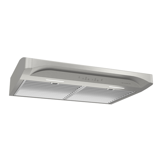
- Page 1 WWW.VENMAR.CA WWW.VENMAR.CA RANGE HOOD Series: VCQLA1 INSTALLATION, USE AND CARE MANUAL Serial number: 99045657-005G...
- Page 2 Safety ....... . . 3-4 Operation ......5-6 Cleaning and Maintenance .
- Page 3 READ AND SAVE THESE INSTRUCTIONS Intended for domestic cooking only INSTALLER: LEAVE THIS MANUAL WITH HOMEOWNER. Register your range hood online at www.venmar.ca. WARNING TO REDUCE THE RISK OF FIRE, ELECTRIC SHOCK, OR INJURY TO PERSONS, OBSERVE THE FOLLOWING: • Use this unit only in the manner intended by the manufacturer. If you have questions, contact the manufacturer at the address or telephone number listed in the warranty.
- Page 4 WARNING TO REDUCE THE RISK OF A RANGE TOP GREASE FIRE: a) Never leave surface units unattended at high settings. Boilovers cause smoking and greasy spillovers that may ignite. Heat oils slowly on low or medium settings. b) Always turn hood ON when cooking at high heat or when flambeing food (i.e.: Crêpes Suzette, Cherries Jubilee, Peppercorn Beef Flambé).
- Page 5 Operation Always turn your hood on before you begin cooking to establish an air flow in the kitchen. Let the blower run for a few minutes to clear the air after you turn off the range. This will help keep the whole kitchen cleaner and fresher. This hood is equipped with infrared sensing controls.
- Page 6 LIGHTING/LIGHT INTENSITY CHANGE To turn the lighting ON, touch the sensor corresponding to the desired lighting intensity and the sensor will illuminate. When the lighting is ON, touch the sensor corresponding to the active light intensity to turn the lighting OFF and memorize the intensity. The LED modules included with this hood are the latest in LED cooktop illumination technology specially designed to operate in the elevated temperatures of cooking - offering bright lighting and lasting up to 25 times as long as a standard bulb and greater reliability than typical replacement...
- Page 7 Cleaning and Maintenance Proper maintenance of the Range Hood will assure proper performance of the unit. MOTORS The motors are permanently lubricated and never need oiling. If the motor bearings make excessive or unusual noise, replace the motor with the exact service motor. The fan wheel should also be replaced.
- Page 8 For ADA compliance installation guidelines, please type the model number into our website. Recommended Tools and Accessories for Installation • Measuring tape • Phillips screwdriver no. 2 • Nutdriver or socket 11/32” • Flat blade screwdriver (to open knockout holes) •...
- Page 9 Contents Before proceeding to the installation, check the contents of the box. If items are missing or damaged, contact the manufacturer. Make sure that the following items are included: VCQLA1 Series IND INSIDE ONE PACKAGING STYROFOAM OF HOOD (1) 3¼” 10”...
- Page 10 Prepare the Hood 1 ] If present, remove all protective polyfilm from the hood and/or parts. 2 ] Remove 2 screws from top of hood (see illustration below). Keep the screws for further use. 2 SCREWS 3 ] Using the finger cup, remove the grease filters from the hood by pushing down and tilting ...
- Page 11 5 ] Remove the parts bag, taped on the inner back of hood, near the left corner. Remove the EZ1 brackets from inside the hood by cutting off the tie wrap. Discard the tie wrap. BRACKETS PARTS BAG LOCATION 6 ] Remove Electrical Power Cable Knockout from top (vertical wiring) or back (horizontal wiring) of hood.
- Page 12 DUCTED INSTALLATION ONLY 8 ] Remove 3¼” x 10” vertical, 3¼” x 10” horizontal (both are the rectangular central knockout plates, see hatched areas) or 7-inch round knockout plate as appropriate for your ducting method (see F 1 A and 1 B). IGURES IGURE IGURE...
- Page 13 Prepare the Hood Location NOTE: Before starting installation, read all the steps of these instructions. Use the illustration below to identify your kitchen cabinet type. FRAMED CABINET FRAMELESS CABINET This manual covers 2 kinds of installation: the standard (without EZ1 brackets) and the EZ1 one-person installation system (using included template and brackets).
- Page 14 4 ] Drill a 1/8” dia. pilot hole for house wiring, at B location on template. 5 ] Use a sharp pencil or 1/8” drill bit to mark the locations for the appropriate duct access holes (16 locations for 7” round duct, or 4 corner locations for rectangular duct). Remove the template.
- Page 15 FRAMELESS CABINET Refer to the marking on brackets to determine the correct installation side and orientation. 7/64” Align the corresponding bracket to the cabinet side, while placing rear end of bracket against the wall. Draw a line on the outer edge of the bracket (as shown). ...
- Page 16 Install the Hood (EZ1 Bracket) OTE: The following procedure applies to both frame or frameless cabinet installations. 1 ] Run house power cable between service panel and hood location. 2 ] There are 2 pairs of recessed holes on each side of the top of the hood (on rear: A and B, on front C and D on illustration below);...
- Page 17 7 ] For framed cabinet, secure the hood to the EZ1 brackets using four (4) no. 8-18 x 1/2” metal screws (included in parts bag). Insert two (2) screws per side, in the slots (as shown in insets on illustration below). 8 ] For frameless cabinet, secure the hood to the cabinet using four (4) no.
- Page 18 Standard Installation (without EZ1 brackets) 1 ] Use the proper diagram below for placement of ductwork and electrical cutout in cabinet or wall. For a non-ducted installation, DO NOT cut a duct access hole, only cut the hole for electrical wiring. 3¼"...
- Page 19 Install the Hood (Standard Installation) OTE: Two installers are recommended because of the weight of this hood. 1 ] Run house power cable between service panel and hood location. For hood with power cable access located on back of hood, run the house power cable into the hood through the strain relief previously installed in step 6 on page 11.
- Page 20 Connect the Wiring WARNING Risk of electric shock. Electrical wiring must be done by qualifi ed personnel in accordance with all applicable codes and standards. Before connecting wires, switch power off at service panel and lock service disconnecting means to prevent power from being switched on accidentally.
- Page 21 VCQLA1 SERIES ( SECOND GENERATION...
- Page 22 EPAIRS In order to ensure your unit remains in good working condition, you must use Venmar Ventilation ULC genuine replacement parts only. Venmar Ventilation ULC genuine replacement parts are specially designed for each unit and are manufactured to comply with all the applicable certification standards and maintain a high standard of safety.
- Page 23 EPAIRS In order to ensure your unit remains in good working condition, you must use Venmar Ventilation ULC genuine replacement parts only. Venmar Ventilation ULC genuine replacement parts are specially designed for each unit and are manufactured to comply with all the applicable certification standards and maintain a high standard of safety.
- Page 24 Limited Warranty Warranty Period and Exclusions: Venmar Ventilation ULC (the “Company”) warrants to the original consumer purchaser of its product (“you”) that the product (the “Product”) will be free from material defects in the Product or its workmanship for a period of five (5) years from the date of original purchase (or such longer period as may be required by applicable law). For Range Hood Product that includes built-in LED modules, the Company warrants the LED modules and driver to be free from material defects for a period of three (3) years from the date of purchase.
- Page 25 WWW.VENMAR.CA WWW.VENMAR.CA HOTTE DE CUISINIÈRE Série : VCQLA1 MANUEL D’INSTALLATION, D’UTILISATION ET D’ENTRETIEN Numéro de série : 99045657-005G...
- Page 26 Sécurité ....... 3-4 Fonctionnement ......5-6 Nettoyage et entretien .
- Page 27 VEUILLEZ LIRE ET CONSERVER CES DIRECTIVES Conçues pour usage domestique seulement INSTALLATEUR : LAISSER CE MANUEL AU PROPRIÉTAIRE. Enregistrez votre hotte en ligne à www.venmar.ca AVERTISSEMENT AFIN DE RÉDUIRE LES RISQUES D’INCENDIE, D’ÉLECTROCUTION OU DE BLESSURES CORPORELLES, SUIVEZ LES DIRECTIVES SUIVANTES : •...
- Page 28 AVERTISSEMENT AFIN DE RÉDUIRE LES RISQUES DE FEU DE CUISINIÈRE : Ne jamais laisser les appareils de cuisson sans surveillance lorsqu’ils sont réglés à feu vif. Les débordements engendrent de la fumée et des déversements graisseux pouvant s’enflammer. Chauffez l’huile lentement, à feu doux ou moyen. Mettez toujours la hotte en marche lorsque vous cuisinez à...
- Page 29 Fonctionnement Toujours mettre en marche la hotte avant de commencer la cuisson afin d’établir une circulation d’air dans la cuisine. Laisser également la hotte fonctionner quelques minutes après l’arrêt de la cuisinière afin de nettoyer l’air. Cela aidera à maintenir la cuisine plus propre et plus fraîche. Cette hotte est munie d’une commande à...
- Page 30 ÉCLAIRAGE/MODIFICATION DE L’INTENSITÉ D’ÉCLAIRAGE Pour activer l’éclairage, toucher le capteur correspondant à l’intensité d’éclairage souhaitée. Le capteur s’illuminera et l’éclairage s’activera. Lorsque l’éclairage est activé, toucher le capteur correspondant à l’intensité d’éclairage activée pour l’éteindre et garder en mémoire la dernière intensité utilisée. Cette hotte est munie de modules DEL offrant un éclairage brillant, issus de la plus récente technologie en matière d’éclairage de surface de cuisson et spécialement conçus pour fonctionner dans un environnement à...
- Page 31 Nettoyage et entretien L’entretien adéquat de la hotte préservera ses performances. MOTEURS Les moteurs sont lubrifiés en permanence et n’ont pas besoin d’être huilés. Si les roulements de moteur sont anormalement bruyants, remplacer le moteur uniquement par le même modèle. La roue du ventilateur doit aussi être remplacée.
- Page 32 Pour connaître les lignes directrices de l’ADA (Americans with Disabilities Act) concernant l’installation, veuillez entrer votre numéro de modèle dans notre site Internet. Matériel requis pour l’installation • Ruban à mesurer • Tournevis Phillips n° 2 • Tourne-écrou ou douille de 11/32 po •...
- Page 33 Contenu Avant de procéder à l’installation, vérifier le contenu de la boîte. Si des articles sont manquants ou endommagés, contacter le manufacturier. S’assurer que les articles suivants sont inclus : Série VCQLA1 * À ’ ’ INTÉRIEUR D UN STYROMOUSSE PROTECTEUR DE LA HOTTE (1) A DAPTATEUR...
- Page 34 Préparation de la hotte 1 ] Retirer toute pellicule de plastique protectrice sur la hotte et/ou ses pièces. 2 ] Retirer les deux vis du dessus de la hotte (voir l’illustration ci-dessous). Garder les vis pour usage ultérieur. 2 VIS 3 ] Enlever les filtres à...
- Page 35 5 ] Retirer le sac de pièces fixé au dos interne de la hotte avec du ruban adhésif, et détacher les supports EZ1 de l’intérieur de la hotte en coupant leur attache autobloquante. Se défaire de l’attache autobloquante. SUPPORTS EZ1 EMPLACEMENT DU SAC DE PIÈCES 6 ] Retirer l’ouverture préamorcée du câble d’alimentation électrique du dessus (câblage vertical)
- Page 36 INSTALLATION AVEC CONDUITS SEULEMENT 8 ] Retirer les ouvertures préamorcées de 3¼ po x 10 po verticale, 3¼ po x 10 po horizontale (les 2 étant les plaques rectangulaires centrales, voir les zones hachurées), ou 7 po ronde selon le mode d’évacuation choisi (voir les F 1 A et 1 B).
- Page 37 Préparation de l’emplacement de la hotte NOTE : Avant de commencer l’installation, veuillez lire toutes les étapes de cette instruction. Identifier votre type d’armoire de cuisine à l’aide de l’illustration ci-dessous. ARMOIRE À FOND EN RETRAIT ARMOIRE À FOND ÉGAL Ce manuel couvre deux types d’installation : l’installation standard (sans les supports EZ1) et le système d’installation par une personne EZ1 (en utilisant le gabarit et les supports inclus).
- Page 38 4 ] Percer un avant-trou de 1/8 po de diamètre pour le câble d’alimentation, à l’emplacement B sur le gabarit. 5 ] Utiliser un crayon pointu ou un foret de 1/8 po pour marquer les repères du trou pour le conduit approprié (16 endroits pour le conduit rond de 7 po, ou aux 4 coins pour les conduits rectangulaires).
- Page 39 ARMOIRE À FOND ÉGAL Voir les inscriptions sur les supports pour les installer dans le bon sens (inscriptions en anglais seulement : front = avant, left = gauche, lean on rear wall = appuyer sur le mur arrière). 7/64” Aligner le support correspondant au côté...
- Page 40 Installation de la hotte (avec supports EZ1) OTE : La procédure convient autant pour les armoires à fond en retrait qu’à fond égal. 1 ] Acheminer le câble d’alimentation depuis le panneau de distribution de la maison jusqu’à l’emplacement de la hotte. 2 ] De chaque côté...
- Page 41 7 ] Pour une armoire à fond en retrait, fixer la hotte au supports EZ1 à l’aide de quatre (4) vis à métaux n° 8-18 x 1/2 po (incluses dans le sac de pièces). Insérer deux (2) vis par côté, dans les fentes (tel qu’il est démontré...
- Page 42 Installation standard (sans supports EZ1) 1 ] Utiliser le diagramme approprié ci-dessous pour déterminer l’emplacement exact des coupes à effectuer pour le conduit et le fil d’alimentation électrique dans l’armoire ou le mur. Pour une installation en recirculation, NE PAS découper un trou pour le conduit. LIGNE ÉVACUATION VERTICALE DE CENTRE...
- Page 43 Installation de la hotte (installation standard) OTE : Deux installateurs sont recommandés pour l’installation en raison du poids de cette hotte. 1 ] Acheminer le câble d’alimentation électrique du panneau de distribution jusqu’à l’emplacement de la hotte. Si l’ouverture pour le câble d’alimentation est à l’arrière de la hotte, insérer le câble d’alimentation dans la hotte à...
- Page 44 Branchement électrique AVERTISSEMENT Risque d’électrocution. Le raccordement électrique doit être effectué par du personnel qualifi é conformément aux codes et aux standards en vigueur. Avant d’effectuer le branchement, coupez l’alimentation électrique au panneau de distribution et verrouillez-le pour éviter une mise en marche accidentelle.
- Page 45 SÉRIE VCQLA1 ( DEUXIÈME GÉNÉRATION 21 21...
- Page 46 IÈCE DE REMPLACEMENT ET SERVICE Pour assurer le bon fonctionnement de votre appareil, vous devez toujours utiliser des pièces d’origine provenant de Venmar Ventilation ULC. Les pièces d’origine de Venmar Ventilation ULC sont spécialement conçues pour satisfaire toutes les normes de certification de sécurité...
- Page 47 IÈCE DE REMPLACEMENT ET SERVICE Pour assurer le bon fonctionnement de votre appareil, vous devez toujours utiliser des pièces d’origine provenant de Venmar Ventilation ULC. Les pièces d’origine de Venmar Ventilation ULC sont spécialement conçues pour satisfaire toutes les normes de certification de sécurité...
- Page 48 Garantie limitée Période de garantie et exclusions : Venmar Ventilation ULC (la « Société ») garantit au consommateur acheteur initial (« vous ») de son produit (le « Produit ») que celui-ci est exempt de tout vice de matériau ou de fabrication pour une période de cinq (5) ans à...