Publicité
Les langues disponibles
Les langues disponibles
Liens rapides
All manuals and user guides at all-guides.com
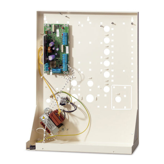
ATS1203(N)/ATS1204(N) 8 to 32 Zone DGP
with 3A Power Supply Installation Sheet
EN DE FR
IT
1
2
(1)
(2)
(3)
(4)
(5)
(6)
(3)
3
(2)
(1)
(3)
(3)
(3)
(7)
(4)
(4)
(4)
(4)
(4)
(5)
(5)
(5)
(6)
(7)
(7)
(8)
(8)
(9)
(9)
(9)
© 2019 UTC Fire & Security Americas Corporation, Inc.
P/N 1064130 (ML) • REV E • ISS 01JUL19
1 / 24
Publicité

Manuels Connexes pour Interlogix ATS1203


Sommaire des Matières pour Interlogix ATS1203
-
Page 14: Retrait/Dépose De Batterie
ST590) pour être conforme à la norme CEI 79-2 niveau 2. Recommandations générales d’installation Le kit d’autoprotection à l’arrachement n’est pas inclus Note : L’ATS1203(N)/ATS1204(N) ont été conçue, assemblée et dans ce produit. testée conformément aux normes en vigueur notamment en matière de sécurité électrique, et d’immunité aux interférences Pour plus d’informations sur les raccordements de la carte... -
Page 15: Diagrammes Des Connexions
(15) Sirène extérieure (S+/S−) et zones terminal de station d’armement portant le signe « − ». (16) Bus de données du système Voir « Câblage ATS1203(N)/ATS1204(N) avec les centrales (17) Contact d’autoprotection à l’arrachement normalement fermé (18) Contact d’autoprotection normalement fermé... -
Page 16: Blindage Des Câbles
Numerotation des zones (256 zones) Raccordement à la terre de coffrets dans un même L'ATS1203(N)/ATS1204(N) dispose de 8 zones qui peuvent bâtiment. être étendues, grâce à l'ATS 1202 (8 zones), à un maximum de 32 zones. -
Page 17: Spécifications Techniques
(ATS1810), soit jusqu’à 4 cartes ATS1811 / 2 cartes ATS1820 (dépendant de la configuration du DGP). Static Outputs par Dimensions coffret ATS1203: 370 x 475 x 160 mm métallique HxWxL défaut (ATS1810 * 2 max). ATS1204: 460 x 475 x 160 mm...