Publicité
Liens rapides
NOTICE DE MISE EN OEUVRE
IMPLEMENTATION MANUAL
Tous les schémas, dessins, spécifications, plans et détails de poids, tailles et dimensions figurant dans la
documentation technique ou commerciale de Nexans ont un caractère purement indicatif et ne sauraient
engager Nexans ou être traités comme constitutifs d'une garantie de la part de Nexans.
All drawings, designs, specifications, plans and particulars of weights, size and dimensions contained in the
technical or commercial documentation of Nexans is indicative only and shall not be binding on Nexans or be
All manuals and user guides at all-guides.com
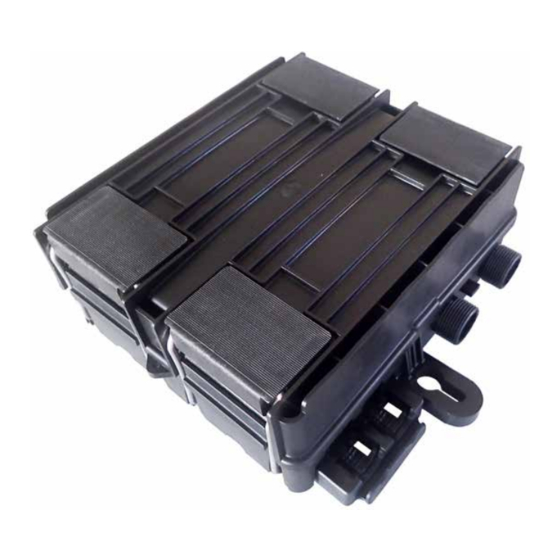
BlackBox
36 FIBRES G.652
treated as constituting a representation on the part of Nexans.
2 0 2 1 1 7 3 0 . p n g
Document : ABS1365/E
Date : 28/02/2017
Publicité

Manuels Connexes pour Nexans BLACKBOX 36FO G652


Sommaire des Matières pour Nexans BLACKBOX 36FO G652
- Page 1 All drawings, designs, specifications, plans and particulars of weights, size and dimensions contained in the technical or commercial documentation of Nexans is indicative only and shall not be binding on Nexans or be treated as constituting a representation on the part of Nexans.
- Page 2 All manuals and user guides at all-guides.com BLACKBOX 36FO G652 Table des matières Table Of Contents INTRoDUcTIoN OVERVIEW .......................4 1.1. CARACTÉRISTIQUES TECHNIQUES TECHNICAL CHARACTERISTICS ................. 4 1.2. COMPOSITION CONTENTS ....................... 6 1.3. ACCESSOIRES FOURNIS PROVIDED ACCESSORIES ..................10 accÈS aU BoÎTIER ACCESSING THE CLOSURE ................11...
- Page 3 All manuals and user guides at all-guides.com BLACKBOX 36FO G652 RaccoRDEMENT DES clIENTS CONNECTING THE CUSTOMERS ..............29 5.1. PRÉPARATION D’UN CÂBLE CLIENT PREPARING A CUSTOMER CABLE ................29 5.2. MISE EN PLACE DU CÂBLE CABLE INSTALLATION....................30 5.3. FIXATION DU CÂBLE DANS LE BOÎTIER FIXING THE CABLE IN THE CLOSURE ...............
- Page 4 All manuals and user guides at all-guides.com BLACKBOX 36FO G652 INTRoDUcTIoN OVERVIEW Le boîtier optique Blackbox d’épissurage Blackbox splicing and extraction et d’extraction a été conçu pour assurer la closure has been designed to protect protection des épissures de câbles optiques buried, underground, and overhead cable enterrés, souterrains et aériens.
- Page 5 All manuals and user guides at all-guides.com BLACKBOX 36FO G652 REQUIRED TOOLS OUTILS NÉCESSAIRES – Torx screwdriver T25 (6IP) Ø5mm – Tournevis Torx T25 (6IP) Ø5 mm) – Pozidriv screwdriver no.2 – Tournevis Pozidriv n°2 – Small screwdriver – Tournevis petit modèle –...
- Page 6 All manuals and user guides at all-guides.com BLACKBOX 36FO G652 1.2. Composition Contents The Blackbox is made up of the following La Blackbox est composée des éléments elements: suivants : a. un corps équipé de : a. a body equipped with: quatre grenouillères articulées...
- Page 7 All manuals and user guides at all-guides.com BLACKBOX 36FO G652 ABS1365/E 7/40...
- Page 8 All manuals and user guides at all-guides.com BLACKBOX 36FO G652 c. un organiseur comportant : c. an organizer made up of: a fixed plate clamped at the un plateau fixe arrimé sur le bottom of the closure, fond du boîtier, un réservoir de stockage,...
- Page 9 All manuals and user guides at all-guides.com BLACKBOX 36FO G652 ABS1365/E 9/40...
- Page 10 All manuals and user guides at all-guides.com BLACKBOX 36FO G652 1.3. Accessoires fournis Provided accessories Désignation Description Kit de fixation du câble résau composé Kit for fixing the network cable de : made up of: - 6 vis autotaraudeuses M5 x 25 mm,...
- Page 11 All manuals and user guides at all-guides.com BLACKBOX 36FO G652 accÈS aU BoÎTIER ACCESSING THE CLOSURE 2.1. Ouverture - fermeture du boîtier Opening - closing the closure Grenouillère Draw latch 2.2. Ouverture - fermeture de l’organiseur cassettes Opening - closing the tray organizer 2.3.
- Page 12 All manuals and user guides at all-guides.com BLACKBOX 36FO G652 PRÉPaRaTIoN DU BoÎTIER PREPARING THE CLOSURE 3.1. Mise en place des bouchons et joints d’étanchéité Installing the plugs and seals 1. Placer les bouchons translucides dans les 1. Push the translucent plugs in the seals joints en poussant jusqu’en butée.
- Page 13 All manuals and user guides at all-guides.com BLACKBOX 36FO G652 3.2. Mise en place des étriers Installing the clamps Installer les étriers de fixation des aramides ou Mount on the rear cover the clamps allowing des porteurs sur le capot arrière.
- Page 14 All manuals and user guides at all-guides.com BLACKBOX 36FO G652 3.4. Préparation des cassettes Preparing the trays 1. Remove the paper from the cover of the 1. Enlever le papier de protection du couvercle de la cassette supérieure. upper tray.
- Page 15 All manuals and user guides at all-guides.com BLACKBOX 36FO G652 3.5. Fixation murale Wall mounting Fixer directement le boîtier sur un mur à l’aide Fix the box on the wall using the screws and des vis et chevilles fournies dans le kit.
- Page 16 All manuals and user guides at all-guides.com BLACKBOX 36FO G652 cÂBlaGE cÔTÉ RÉSEaU NETWORK CABLE WIRING 4.1. Préparation du câble Cable preparation 1. Enlever la gaine du câble sur : 1. Remove the cable sheath on: – piquage épi : 138 cm, –...
- Page 17 All manuals and user guides at all-guides.com BLACKBOX 36FO G652 4.2. Mise en place du câble réseau Network cable installation 1. Abraser la (les) gaine(s) de câble à l’aide 1. Abrade the cable sheath using the cloth (1) de la toile fournie (1), perpendiculairement provided, in a perpendicular position to the à...
- Page 18 All manuals and user guides at all-guides.com BLACKBOX 36FO G652 4. Poser le mastic sur la gaine extérieure, à 4. Apply sealant on the sheath at a distance 10 mm de l’extrémité de la gaine. of 10mm from the sheath end.
- Page 19 All manuals and user guides at all-guides.com BLACKBOX 36FO G652 7. Répéter l’opération pour fixer la gaine du 7. Repeat the procedure to clamp the second deuxième câble (3). cable sheath (3). 8. Serrer les vis pour bloquer les renforts 8.
- Page 20 All manuals and user guides at all-guides.com BLACKBOX 36FO G652 Fig. Piquage droit Straight midspan 10. Couper au ras de la gaine les micro- 10. Cut level with the sheath the micromodules modules qui seront acheminés dans les to be routed towards the trays.
- Page 21 All manuals and user guides at all-guides.com BLACKBOX 36FO G652 12. Fixer le capot amovible sur le boîtier à 12. Fasten the removable cover onto the closure l’aide des 6 vis fournies, en commençant using the 6 screws provided , starting with par les 2 vis centrales.
- Page 22 All manuals and user guides at all-guides.com BLACKBOX 36FO G652 4.3. Cheminement du/des micro-module(s) vers la/les cassette(s) Micromodules routing towards the trays 1. Séparer depuis le talon du câble les micro- 1. Single out from the extremity of the cable modules qui seront acheminés dans les...
- Page 23 All manuals and user guides at all-guides.com BLACKBOX 36FO G652 Fig. Piquage droit Straight midspan ABS1365/E 23/40...
- Page 24 All manuals and user guides at all-guides.com BLACKBOX 36FO G652 3. Diriger les micro-modules à raccorder vers 3. Route the micromodules to be connected les cassettes et les bloquer dans les peignes. towards the trays and block them in the combs.
- Page 25 All manuals and user guides at all-guides.com BLACKBOX 36FO G652 Fig. Piquage droit Straight midspan ABS1365/E 25/40...
- Page 26 All manuals and user guides at all-guides.com BLACKBOX 36FO G652 4.4. Lovage des fibres en attente d’épissurage Coiling of fibres awaiting splicing 1. Préparer les fibres réseau pour la mise 1. Prepare the awaiting network fibres: en attente : –...
- Page 27 All manuals and user guides at all-guides.com BLACKBOX 36FO G652 6. Répéter l’opération dans les cassettes n°2 6. Repeat the same steps in trays no. 2 and et n°3. no. 3. Cassette n° 1 Micro-module(s) Tray no. 1 Micromodule(s) Fibres nues en attente d’épissurage...
- Page 28 All manuals and user guides at all-guides.com BLACKBOX 36FO G652 7. Positionner les colliers de fixation (1) des 7. Position the customer cables fixation câbles clients sur le couvercle tel que sur la collars (1) on the cover as shown below.
- Page 29 All manuals and user guides at all-guides.com BLACKBOX 36FO G652 RaccoRDEMENT DES clIENTS CONNECTING THE CUSTOMERS Pour connaître l’ordre de raccordement To know the recommended connection order recommandé en fonction du type de joint depending on the seal type used, refer to utilisé, voir Annexe A.
- Page 30 All manuals and user guides at all-guides.com BLACKBOX 36FO G652 5.2. Mise en place du câble Cable installation 1. Dévisser complè- 1. Unscrew the com- tement l’écrou de pression nut of the compression du joint seal. d’étanchéité. 2. Retirer le bouchon.
- Page 31 All manuals and user guides at all-guides.com BLACKBOX 36FO G652 4. Glisser la fibre 900 µm et les mèches 4. Slide the 900µm fibre and the aramid yarns aramides à travers l’écrou et le joint through the nut and seal.
- Page 32 All manuals and user guides at all-guides.com BLACKBOX 36FO G652 5.3. Fixation du câble dans le boîtier Fixing the cable in the closure 1. Amener la gaine extérieure du câble 1. Bring the cable sheath 3mm beyond the 3 mm au-delà de la patte de fixation.
- Page 33 All manuals and user guides at all-guides.com BLACKBOX 36FO G652 5.4. Cheminement du(des) micro-module(s) jusqu’à la cassette Routing the micromodule(s) towards the tray 1. Acheminer le(s) micro-module(s) du 1. Route the micromodule(s) of the first premier câble client jusqu’à l’entrée de la customer cable towards the tray(s) (des) cassette(s), comme illustré...
- Page 34 All manuals and user guides at all-guides.com BLACKBOX 36FO G652 2. Faire cheminer les autres micro- 2. Route the other customer cables modules de câbles clients comme illustré micromodules towards the tray(s) ci-dessous : entry(/ies) as shown below. Exception : les fibres des câbles clients n°7, 8, 9 entrent dans la (les) cassette(s) du même...
- Page 35 All manuals and user guides at all-guides.com BLACKBOX 36FO G652 5.5. Préparation et fixation du micro-module à l’entrée de la cassette Preparing and fixing the micromodule at the entry of the tray 1. Fixer la fibre 900 µm dans le peigne 1.
- Page 36 All manuals and user guides at all-guides.com BLACKBOX 36FO G652 5.6. Épissurage des fibres Fibres splicing 1. Récupérer le smoove à l’extrémité des 1. Retrieve the smoov at the end of the fibres en attente et délover complètement awaiting fibres and uncoil all the fibres.
- Page 37 All manuals and user guides at all-guides.com BLACKBOX 36FO G652 PRESSURISaTIoN PRESSURISATION 1. Dévisser le capuchon de la valve de 1. Unscrew the plug of the pressurisation valve. pressurisation. 2. Pressuriser le boîtier à 400 mbar pendant 2. Pressurize the closure to 5.8 PSI during 15 min afin de détecter une fuite éventuelle...
- Page 38 All manuals and user guides at all-guides.com BLACKBOX 36FO G652 aNNExES/aPPENDIcES oRDRE DE RaccoRDEMENT DES cÂBlES clIENTS CONNECTION ORDER OF THE CUSTOMER CABLES Fig. Joints 4 trous 4-hole seals Câble réseau positionné en épi Network cable in a mid- N° clients Côté...
- Page 39 All manuals and user guides at all-guides.com BLACKBOX 36FO G652 Fig. Joints 2 trous Dual-hole seals Câble réseau positionné en épi N° clients Network cable in a mid- Côté droit Customer No. span application Right side Bouchons d’étanchéité Sealing plugs N°...
- Page 40 All drawings, designs, specifications, plans and particulars of weights, size and dimensions contained in the technical or commercial documentation of Nexans is indicative only and shall not be binding on Nexans or be treated as constituting a representation on the part of Nexans.