Télécharger Imprimer la page

Publicité

Les langues disponibles

Les langues disponibles

Liens rapides

P67A-C45/ P67A-C43/
P67S-C43/ P67A-S40
series
MS-7673 (v1.x) Mainboard
G52-76731X7

Publicité

loading

Sommaire des Matières pour MSI MS-7673

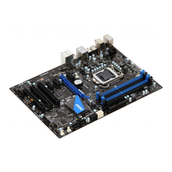
  • Page 1 P67A-C45/ P67A-C43/ P67S-C43/ P67A-S40 series MS-7673 (v1.x) Mainboard G52-76731X7...
  • Page 2 Alternatively, please try the following help resources for further guidance. ◙ Visit the MSI website for FAQ, technical guide, BIOS updates, driver updates, and other information: http://www.msi.com/index.php?func=service ◙ Contact our technical staff at: http://ocss.msi.com...
  • Page 3 MS-7673 MS-7673 Safety Instructions ■ Always read the safety instructions carefully. ■ Keep this User’s Manual for future reference. ■ Keep this equipment away from humidity. ■ Lay this equipment on a reliable flat surface before setting it up. ■...
  • Page 4 VOIR LA NOTICE D’INSTALLATION AVANT DE RACCORDER AU RESEAU. Micro-Star International MS-7673 This device complies with Part 15 of the FCC Rules. Operation is subject to the follow- ing two conditions: this device may not cause harmful interference, and this device must accept any interference received, including interference that may cause undesired operation.
  • Page 5 MSI will comply with the product take back requirements at the end of life of MSI-branded products that are sold into the EU.
  • Page 6 MSI će poštovati zahtev o preuzimanju ovakvih proizvoda kojima je istekao vek trajanja, koji imaju MSI oznaku i koji su prodati u EU. Ove proiz- vode možete vratiti na lokalnim mestima za prikupljanje.
  • Page 7 MSI si adeguerà a tale Direttiva ritirando tutti i prodotti marchiati MSI che sono stati venduti all’interno dell’Unione Europea alla fine del loro...
  • Page 8 Preface Preface Contents Copyright Notice .................... ii Trademarks ....................ii Revision History..................... ii Technical Support..................ii Safety Instructions ..................iii FCC-B Radio Frequency Interference Statement.......... iv WEEE (Waste Electrical and Electronic Equipment) Statement ....v English ...................... En-1 Mainboard Specifications ...................En-2 Quick Components Guide ..................En-4 Screw Holes .......................En-5 CPU (Central Processing Unit) ................En-6...
  • Page 9 MS-7673 MS-7673 Français ..................... Fr-1 Spécifications ......................Fr-2 Guide Rapide Des Composants ................Fr-4 Trous Taraudés ....................Fr-5 Processeur : CPU ....................Fr-6 Mémoire ......................Fr-10 Connecteurs d’alimentation ................Fr-12 Panneau arrière ....................Fr-13 Connecteurs ......................Fr-16 Indicateur de statut LED (en option) ..............Fr-23 Cavalier ......................Fr-24 Emplacements ....................Fr-25 Réglage BIOS ....................Fr-27...
  • Page 11 English P67A-C45/ P67A-C43/ P67S-C43/ P67A-S40 Series Europe version...
  • Page 12 MS-7673 Mainboard MS-7673 Mainboard Mainboard Specifications Processor Support ■ Intel processor in the LGA1155 package ® (For the latest information about CPU, please visit http://www.msi.com/index. php?func=cpuform2) Base Clock ■ 100 MHz Chipset ■ Intel P67 chipset ® Memory Support ■...
  • Page 13 ■ ATX (30.5 cm X 21.5 cm) Mounting ■ 6 mounting holes * If you need to purchase accessories and request the part numbers, you could search the product web page and find details on our web address http://www.msi.com/index. En-3...
  • Page 14 MS-7673 Mainboard MS-7673 Mainboard Quick Components Guide SYSFAN1, En-17 CPUFAN, En-17 DDR3, En-10 JPWR2, En-12 CPU, En-6 SYSFAN4, En-17 JCI1, En-22 Back Panel, En-13 JPWR1, En-12 PCIE, En-25 SATA1~6, En-16 JBAT1, En-24 PCI, En-26 JCOM1, En-17 SYSFAN2, En-17 SYSFAN3, En-17...
  • Page 15 Screw Holes When you install the mainboard, you have to place the mainboard into the chassis in the correct direction. The locations of screws holes on the mainboard are shown as below. The side has to toward the rear, the position for the I/O shield of the chassis.
  • Page 16 When you are installing the CPU, make sure to install the cooler to prevent overheating. If you do not have the CPU cooler, consult your dealer before turning on the computer. For the latest information about CPU, please visit http://www.msi.com/index. php?func=cpuform2...
  • Page 17 CPU & Cooler Installation When you are installing the CPU, make sure the CPU has a cooler attached on the top to prevent overheating. Meanwhile, do not forget to apply some thermal paste on CPU before installing the heat sink/cooler fan for better heat dispersion. Follow the steps below to install the CPU &...
  • Page 18 MS-7673 Mainboard MS-7673 Mainboard Visually inspect if the CPU is seated Engage the load lever while pressing well into the socket. If not, take out down lightly onto the load plate. the CPU with pure vertical motion and reinstall. Alignment Key...
  • Page 19 Align the holes on the mainboard with Press the four hooks down to fasten the heatsink. Push down the cooler the cooler. until its four clips get wedged into the holes of the mainboard. Turn over the mainboard to confirm Finally, attach the CPU Fan cable to that the clip-ends are correctly in- the CPU fan connector on the main-...
  • Page 20 MS-7673 Mainboard MS-7673 Mainboard Memory These DIMM slots are used for installing memory modules. For more information on compatible components, please visit http://www.msi.com/index.php?func=testreport DDR3 240-pin, 1.5V 48x2=96 pin 72x2=144 pin Dual-Channel mode Population Rule In Dual-Channel mode, the memory modules can transmit and receive data with two data bus lines simultaneously.
  • Page 21 Installing Memory Modules The memory module has only one notch on the center and will only fit in the right orientation. Insert the memory module vertically into the DIMM slot. Then push it in until the golden finger on the memory module is deeply inserted in the DIMM slot. The plastic clip at each side of the DIMM slot will automatically close when the memory module is properly seated.
  • Page 22 MS-7673 Mainboard MS-7673 Mainboard Power Supply ATX 24-pin Power Connector: JPWR1 This connector allows you to connect an ATX 24-pin power supply. To connect the ATX 24-pin power supply, make sure the plug of the power supply is inserted in the proper orientation and the pins are aligned.
  • Page 23 Back Panel For P67A-C45 Optical Keyboard/ Mouse IEEE 1394 Port S/PDIF-Out RS-Out Line-In USB 2.0 Port CS-Out Line-Out SS-Out USB 2.0 Port Coaxial USB 2.0 Port USB 2.0 Port USB 3.0 Port S/PDIF-Out Clear CMOS button For P67A-C43 Optical Keyboard/ Mouse S/PDIF-Out RS-Out Line-In...
  • Page 24 MS-7673 Mainboard MS-7673 Mainboard ▶ Mouse/Keyboard The standard PS/2 mouse/keyboard DIN connector is for a PS/2 mouse/keyboard. ® ® ▶ Clear CMOS Button (optional) There is a CMOS RAM on board that has a power supply from external battery to keep the system configuration data.
  • Page 25 ▶ The standard RJ-45 LAN jack is for connection to Yellow Green/ Orange the Local Area Network (LAN). You can connect a network cable to it. Color LED State Condition Left Yellow LAN link is not established. On(Steady state) LAN link is established. On(brighter &...
  • Page 26 MS-7673 Mainboard MS-7673 Mainboard Connectors Serial ATA Connector: SATA1~6 This connector is a high-speed Serial ATA interface port. Each connector can connect to one Serial ATA device. * The MB layout in this figure is for reference only. SATA1~2 (6 Gb/s) supported by Intel ®...
  • Page 27 Fan Power Connectors: CPUFAN,SYSFAN1~4 The fan power connectors support system cooling fan with +12V. When connecting the wire to the connectors, always note that the red wire is the positive and should be con- nected to the +12V; the black wire is Ground and should be connected to GND. If the mainboard has a System Hardware Monitor chipset on-board, you must use a specially designed fan with speed sensor to take advantage of the CPU fan control.
  • Page 28 MS-7673 Mainboard MS-7673 Mainboard Front Panel Connectors: JFP1, JFP2 These connectors are for electrical connection to the front panel switches and LEDs. The JFP1 is compliant with Intel Front Panel I/O Connectivity Design Guide. ® JFP2 JFP1 Front USB 2.0 Connector: JUSB1...
  • Page 29 Front USB 3.0 Connector: JUSB2 USB 3.0 port is backward-compatible with USB 2.0 devices. Supports data transfer rate up to 5 Gbit/s (SuperSpeed). * The MB layout in this figure is for reference only. USB 3.0 Bracket (optional) Important • Note that the pins of VCC and GND must be connected correctly to avoid possible damage.
  • Page 30 MS-7673 Mainboard MS-7673 Mainboard S/PDIF-Out Connector: JSP1 This connector is used to connect S/PDIF (Sony & Philips Digital Interconnect Format) interface for digital audio transmission. * The MB layout in this figure is for reference only. S/PDIF-Out Bracket (optional) IEEE1394 Connector: J1394_1 (optional) This connector allows you to connect the IEEE1394 device via an optional IEEE1394 bracket.
  • Page 31 TPM Module connector: JTPM1 This connector connects to a TPM (Trusted Platform Module) module (optional). Please refer to the TPM security platform manual for more details and usages. CD-In Connector: JCD1 (optional) This connector is provided for external audio input. En-21...
  • Page 32 MS-7673 Mainboard MS-7673 Mainboard DLED3 Connector: JDLED3 (optional) This is reserved for connecting the MSI future control card. Chassis Intrusion Connector: JCI1 This connector connects to the chassis intrusion switch cable. If the chassis is opened, the chassis intrusion mechanism will be activated. The system will record this status and show a warning message on the screen.
  • Page 33 LED Status Indicators (optional) CPU Power Phase LED These LEDs indicate the current CPU power phase mode. Follow the instructions below to read. Lights CPU is in 3 phase power mode. CPU is in 4 phase power mode. En-23...
  • Page 34 MS-7673 Mainboard MS-7673 Mainboard Jumper Clear CMOS Jumper: JBAT1 There is a CMOS RAM onboard that has a power supply from an external battery to keep the data of system configuration. With the CMOS RAM, the system can automatically boot OS every time it is turned on. If you want to clear the system configuration, set the jumper to clear data.
  • Page 35 Slots PCIE (Peripheral Component Interconnect Express) Slot The PCIE slot supports the PCIE interface expansion card. PCIE x16 Slot PCIE x1 Slot Important When adding or removing expansion cards, make sure that you unplug the power sup- ply first. Meanwhile, read the documentation for the expansion card to configure any necessary hardware or software settings for the expansion card, such as jumpers, switches or BIOS configuration.
  • Page 36 MS-7673 Mainboard MS-7673 Mainboard PCI (Peripheral Component Interconnect) Slot The PCI slot supports LAN card, SCSI card, USB card, and other add-on cards that comply with PCI specifications. 32-bit PCI Slot Important When adding or removing expansion cards, make sure that you unplug the power sup- ply first.
  • Page 37 BIOS Setup This chapter provides basic information on the BIOS Setup program and allows you to configure the system for optimum use. You may need to run the Setup program when: ■ An error message appears on the screen during the system booting up, and requests you to run BIOS SETUP.
  • Page 38 MS-7673 Mainboard MS-7673 Mainboard Control Keyboard Mouse Description <↑ ↓ > Select Item Move the cursor <Enter> Select Icon/ Field Click/ Double- click the left but- <Esc> Jumps to the Exit menu or returns to the previous from a submenu...
  • Page 39 The Main Menu Once you enter BIOS CMOS Setup Utility, the Main Menu will appear on the screen. The Main Menu allows you to select from the setup functions. ▶ Language After entering the Setup menu, you can see a “Language” button. Please click it and select the language, at your desire, for the BIOS setting first.
  • Page 40 MS-7673 Mainboard MS-7673 Mainboard When enter the BIOS Setup utility, follow the processes below for general use. Load Optimized Defaults : Select [Setting] -> [Save & Exit] -> [Restore Defaults] and click on it. And then the screen shows a pop-up message as below. Select [Yes] and click on it to load the default settings for optimal system performance.
  • Page 41 OC Menu Introduction : This menu is for advanced user who want to overclock the mainboard. ▶ Current CPU / DRAM Frequency These items show the current clocks of CPU and Memory speed. Read-only. ▶ CPU Base Frequency [10KHz] This item allows you to set the CPU Base clock (in 10KHz). You may overclock the CPU by adjusting this value.
  • Page 42 MS-7673 Mainboard MS-7673 Mainboard ▶ DRAM Ratio This setting controls the ratio of memory frequency to enable the memory to run at dif- ferent frequency combinations. ▶ Adjusted DRAM Frequency It shows the adjusted DRAM frequency. Read-only. ▶ Extreme Memory Profile(X.M.P) This item is used to enable/disable the Intel Extreme Memory Profile (XMP).
  • Page 43 ▶ tWTR Minimum time interval between the end of write data burst and the start of a col- umn-read command. It allows I/O gating to overdrive sense amplifiers before read command starts. ▶ tRRD Specifies the active-to-active delay of different banks. ▶...
  • Page 44 MS-7673 Mainboard MS-7673 Mainboard ▶ MEMORY-Z Press <Enter> to enter the sub-menu. ▶ DIMM1~4 Memory SPD Press <Enter> to enter the sub-menu. The sub-menu displays the informations of installed memory. ▶ X.M.P Support Information Press <Enter> to enter the sub-menu. These items display the current status of the X.M.P support information.
  • Page 45 ▶ Intel Virtualization Tech This item is used to enable/disable the Intel Virtualization technology. For further information please refer to Intel’s official website. ▶ Power Technology This item allows you to select the Intel Dynamic Power technology mode. ▶ C1E Support To enable this item to read the CPU power consumption while idle.
  • Page 46 Product info menu : It shows the newly information of MSI product. Security menu : It provides the useful antivirus program. Important Please visit the MSI officially website to get the latest drivers and BIOS for better system performance. En-36...
  • Page 47 Deutsch P67A-C45/ P67A-C43/ P67S-C43/ P67A-S40 Serie Europe Version...
  • Page 48 MS-7673 Mainboard MS-7673 Mainboard Spezifikationen Prozessoren ■ Intel Prozessor für Sockel LGA1155 ® (Weitere Informationen finden unter http://www.msi.com/index. php?func=cpuform2) Base-Taktsteuerung ■ 100 MHz Chipsatz ■ Intel P67 Chipsatz ® Speicher ■ 4 DDR3 DIMMs unterstützen DDR3 2133*(OC)/ 1600*(OC)/ 1333/ 1066 DRAM (max.
  • Page 49 1 PCIE x16-Steckplatz ■ 3 PCIE x1-Steckplätze ■ 3 PCI-Steckplätze Form Faktor ■ ATX (30,5 cm X 21,5 cm) Montage ■ 6 Montagebohrungen *Wenn Sie für Bestellungen von Zubehör Teilenummern benötigen, finden Sie diese auf unserer Produktseite unter http://www.msi.com/index.php De-3...
  • Page 50 MS-7673 Mainboard MS-7673 Mainboard Komponenten-Übersicht SYSFAN1, De-17 CPUFAN, De-17 DDR3, De-10 JPWR2, De-12 CPU, De-6 SYSFAN4, De-17 JCI1, De-22 Rücktafel, De-13 JPWR1, De-12 PCIE, De-25 SATA1~6, De-16 JBAT1, De-24 PCI, De-26 JCOM1, De-17 SYSFAN2, De-17 SYSFAN3, De-17 JAUD1, De-19 JDLED3, De-22...
  • Page 51 Schraubenlöcher Wenn Sie das Mainboard zu installieren, müssen Sie das Mainboard in das Chassis in der korrekten Richtung setzen. Die Standorte von Schraubenlöchern auf dem Main- board sind wie nachfolgend gezeigt. Die Seite muss nach hinten, die Position für die E/A-Abschirmung des Chassis.
  • Page 52 MS-7673 Mainboard MS-7673 Mainboard CPU (Prozessor) Wenn Sie die CPU einbauen, stellen Sie bitte sicher, dass Sie auf der CPU einen Kühler anbringen, um Überhitzung zu vermeiden. Verfügen Sie über keinen Kühler, setzen Sie sich bitte mit Ihrem Händler in Verbindung, um einen solchen zu erwerben und zu installieren.
  • Page 53 CPU & Kühler Einbau Wenn Sie die CPU einbauen, stellen Sie bitte sicher, dass Sie auf der CPU einen Kühler anbringen, um Überhitzung zu vermeiden. Vergessen Sie nicht, etwas Siliziumwärmel- eitpaste auf die CPU aufzutragen, bevor Sie den Prozessorkühler installieren, um eine Ableitung der Hitze zu erzielen.
  • Page 54 MS-7673 Mainboard MS-7673 Mainboard Begutachten Sie, ob die CPU richtig Schließen Sie die Abdeckung des im Sockel sitzt. Falls nicht, ziehen Sie Sockels und drücken Sie den Ver- die CPU durch eine rein vertikale Be- schlusshebel mit leichtem Druck wegung wieder heraus. Versuchen nach unten.
  • Page 55 Drücken Sie den Verschlusshebel Führen Sie den CPU-Kühler über mit leichtem Druck nach unten und den CPU-Sockel. arretieren Sie den Hebel unter dem Rückhaltehaken des CPU-Sockels. Drehen Sie das Mainboard um und Schließlich verbinden vergewissern Sie sich, dass das der Stromkabel des CPU Lüfters mit dem Kühler korrekt installiert ist.
  • Page 56 MS-7673 Mainboard MS-7673 Mainboard Speicher Diese DIMM-Steckplätze nehmen Arbeitsspeichermodule auf. Die neusten Infor- mationen über kompatible Bauteile finden Sie unter http://www.msi.com/index. php?func=testreport DDR3 240-polig, 1,5V 48x2=96 Pole 72x2=144 Pole Populationsregeln für Dual-Kanal-Speicher Im Dual-Kanal-Modus können Arbeitsspeichermodule Daten über zwei Datenbusleitun- gen gleichzeitig senden und empfangen.
  • Page 57 Vorgehensweise beim Einbau von Speicher Modulen Die Speichermodulen haben nur eine Kerbe in der Mitte des Moduls. Sie passen nur in einer Richtung in den Sockel. Stecken Sie das Arbeitsspeichermodul senkrecht in den DIMM-Steckplatz ein. Drücken Sie anschließnd das Arbeitsspeichermodul nach unten, bis die Kontakt- seite richtig tief in dem DIMM-Steckplatz sitzt.
  • Page 58 MS-7673 Mainboard MS-7673 Mainboard Stromversorgung ATX 24-poliger Stromanschluss: JPWR1 Mit diesem Anschluss verbinden Sie den ATX 24-poligen Anschluss des Netzteils. Achten Sie bei dem Verbinden des ATX 24-poligen Stromanschlusses darauf, dass der Anschluss des Netzteils richtig auf den Anschluss an der Hauptplatine ausgerichtet ist.
  • Page 59 Rücktafel Für P67A-C45 Optischer IEEE 1394 S/PDIF- Tastatur/ Maus Anschluss Ausgang USB 2.0 RS-Out Line-In Anschluss CS-Out Line-Out SS-Out Koaxialer USB 2.0 USB 2.0 USB 2.0 USB 3.0 S/PDIF- Anschluss Anschluss Anschluss Anschluss Ausgang CMOS leeren-Taste Für P67A-C43 Optischer S/PDIF- Tastatur/ Maus Ausgang USB 2.0...
  • Page 60 MS-7673 Mainboard MS-7673 Mainboard ▶ Maus/Tastatur Die Standard PS/2 Maus/Tastatur Stecker Mini DIN ist für eine PS/2 Maus/Tastatur. ® ® ▶ CMOS leeren-Taste (optional) Auf dem Mainboard befindet sich ein CMOS RAM, dass durch eine zusätzliche Batterie versorgt wird um Daten der Systemkonfiguration zu speichern. Mit diesem CMOS RAM kann das System bei Betätigung des Netzschalters jederzeit automatisch...
  • Page 61 ▶ Die Standard RJ-45 Buchse ist für Anschlus zum Gelb Grün/ Orange an ein Lokales Netzwerk (Local Area Network - LAN). Hier kann ein Netzwerkkabel angeschlossen werden. Farbe LED Status Zustand Links Gelb Keine Verbindung mit dem LAN. An (Dauerleuchten) Verbindung mit dem LAN.
  • Page 62 MS-7673 Mainboard MS-7673 Mainboard Anschlüssen Serial ATA Anschluss: SATA1~6 Der Anschluss ist eine Hochgeschwindigkeitsschnittstelle der Serial ATA. Pro An- schluss kann ein S-ATA Gerät angeschlossen werden. * Das MB-Layout in dieser Abbildung haben nur Orientierungscharakter. SATA1~2 (6 Gb/s) werden durch Intel P67 unterstützt...
  • Page 63 Stromanschlüsse für Lüfter: CPUFAN,SYSFAN1~4 Die Anschlüsse unterstützen aktive Systemlüfter mit +12V. Wenn Sie den Anschluss herstellen, sollten Sie immer darauf achten, dass der rote Draht der positive Pol ist, und mit +12V verbunden werden sollte. Der schwarze Draht ist der Erdkontakt und sollte mit GND verbunden werden.
  • Page 64 MS-7673 Mainboard MS-7673 Mainboard Frontpanel Anschlüsse: JFP1, JFP2 Diese Anschlüsse sind für das Frontpanel. Sie dienen zum Anschluss der Schalter und LEDs des Frontpanels. JFP1 erfüllt die Anforderungen des “Intel Front Panel I/O Con- ® nectivity Design Guide”. JFP2 JFP1 USB 2.0 Vorderanschluss: JUSB1...
  • Page 65 USB 3.0 Vorderanschluss: JUSB2 Der USB 3.0 Anschluss ist abwärtskompatibel mit USB 2.0-Geräten. Unterstützt Daten- transferraten bis 5 Gbit/s (SuperSpeed). * Das MB-Layout in dieser Abbildung haben nur Orientierungscharakter. USB 3.0 Slotblech (optional) Wichtig Bitte beachten Sie, dass Sie die mit VCC (Stromführende Leitung) und GND (Erdlei- •...
  • Page 66 MS-7673 Mainboard MS-7673 Mainboard S/PDIF-Ausgang: JSP1 Die S/PDIF (Sony & Philips Digital Interconnect Format) Schnittstelle wird für die Über- tragung digitaler Audiodaten verwendet. * Das MB-Layout in dieser Abbildung haben nur Orientierungscharakter. S/PDIF-Ausgang Slotblech (optional) IEEE1394 Anschluss: J1394_1 (optional) Mit diesem Anschluss verbinden Sie ein optionales IEEE 1394-Slotblech, das den An- schluss eines IEEE 1394-Gerätes ermöglicht.
  • Page 67 TPM Anschluss: JTPM1 Dieser Anschluss wird für das optionale TPM Modul (Trusted Platform Module) ver- wendt. Weitere Informationen über den Einsatz des optionalen TPM Modules entnehm- en Sie bitte dem TPM Plattform Handbuch. CD-Eingang: JCD1 (optional) Dieser Anschluss wird für externen Audioeingang zur Verfügung gestellt. De-21...
  • Page 68 MS-7673 Mainboard MS-7673 Mainboard DLED3 Anschluss: JDLED3 (optional) Dieser Anschluss ist für Verbindung der zukünftigen Steuerkarte von MSI reserviert. Gehäusekontaktanschluss: JCI1 Dieser Anschluss wird mit einem Kontaktschalter verbunden. Wird das Gehäuse geöff- net, wird der Schalter geschlossen und das System zeichnet dies auf und gibt auf dem Bildschirm eine Warnung aus.
  • Page 69 LED Statusanzeige (optional) CPU Power Phase LED Diese LEDs zeigen den gegenwärtigen CPU Auslastungsgrad an. Lesen Sie die folgen- den Anweisungen. Leuchtet CPU ist in der Phase 3 des Power-Modus. CPU ist in der Phase 4 des Power-Modus. De-23...
  • Page 70 MS-7673 Mainboard MS-7673 Mainboard Steckbrücke Steckbrücke zur CMOS- Löschung: JBAT1 Der Onboard CMOS Speicher (RAM) wird über eine zusätzliche Betterie mit Strom versorgt, um die Daten der Systemkonfiguration zu speichern. Er ermöglicht es dem Betriebssystem, mit jedem Einschalten automatisch hochzufahren. Wenn Sie die Sys- temkonfiguration löschen wollen, müssen Sie die Steckbrücke für kurze Zeit umsetzen.
  • Page 71 Steckplätze PCIE (Peripheral Component Interconnect Express) Steckplatz Der PCIE-Steckplatz unterstützt eine Erweiterungskarte mit der PCIE-Schnittstelle. PCIE x16-Steckplatz PCIE x1-Steckplatz Wichtig Achten Sie darauf, dass Sie zuerst das Netzkabel aus der Steckdose herausziehen, bevor Sie eine Erweiterungskarte installieren oder entfernen. Denken Sie bitte auch daran die Dokumentation der Erweiterungskarte zu lesen, um notwendige Hardware- oder Softwareeinstellungen für die Erweiterungskarte wie z.B.
  • Page 72 MS-7673 Mainboard MS-7673 Mainboard PCI (Peripheral Component Interconnect) Steckplatz Der PCI-Steckplatz kann LAN-Karten, SCSI-Karten, USB-Karten und sonstige Zusatz- karten aufnehmen, die mit den PCI-Spezifikationen konform sind. 32-Bit PCI-Steckplatz Wichtig Achten Sie darauf, dass Sie zuerst das Netzkabel aus der Steckdose herausziehen, bevor Sie eine Erweiterungskarte installieren oder entfernen.
  • Page 73 BIOS Setup Dieses Kapitel enthält Informationen über das BIOS Setup und ermöglicht es Ihnen, Ihr System optimal auf Ihre Anforderungen einzustellen. Notwendigkeit zum Aufruf des BIOS besteht, wenn: ■ Während des Bootvorgangs des Systems eine Fehlermeldung erscheint und Sie zum Aufruf des BIOS SETUP aufgefordert werden. ■...
  • Page 74 MS-7673 Mainboard MS-7673 Mainboard Steuertasten Tastatur Maus Beschreibung <↑ ↓ > Auswahl eines Eintrages Bewegen Sie den Cursor <Enter> Auswahl eines Symbols/ Feldes Klicken/ dop- pelt-klicken Sie mit der linken Maustaste <Esc> Aufruf Exit Menü oder zurück zum Hauptmenü von Untermenü...
  • Page 75 Das Hauptmenü Nachdem Sie das BIOS CMOS Setup Utility, aufgerufen haben, erscheint das Haupt- menü. Es weist fünf Setup-Funktionen. ▶ Language Nach der Eingabe des Einstellungsmenü können Sie eine Schaltfläche “Language”. Bitte klicken Sie darauf und wählen Sie die Sprache für die BIOS-Einstellung. ▶...
  • Page 76 MS-7673 Mainboard MS-7673 Mainboard Wenn Sie das BIOS Dienstprogramm öffnen, folgen Sie den untenstehenden An- weisungen. Laden der gespeicherten Werkseinstellung : Wählen Sie [Setting] -> [Save & Exit] -> [Restore Defaults] und klicken auf diese Schaltfläche. Und dann zeigt der Bild- schrim die folgende PopUp-Meldung.
  • Page 77 OC Menü Einführung: In diesem Menü können Benutzer das BIOS anpassen und übertakten. Bitte führen Sie nur Änderungen durch, wenn Sie sich über das Ergeb- niss sicher sind. Sie sollten Erfahrung beim Übertakten haben, da Sie sonst das Mainboard oder Komponenten des Systems beschädigen können. ▶...
  • Page 78 MS-7673 Mainboard MS-7673 Mainboard nahme bestehen. Die Leistung kann dynamisch erhöht oder reduziert werden. Diese Technologie ist ein Bestandteil neuer Intel Prozessoren. ▶ DRAM Ratio Die Einstellung steuert das Verhältnis der Speicher-Frequenz, um unterschiedliche Kombinationen der Speicherfrequenzen einzustellen. ▶ Adjusted DRAM Frequency Zeigt die Speicherfrequenz an.
  • Page 79 ▶ Minimum Intervall zwischen dem Datenflussende und dem Beginn eines vorgelad- enen Befehls. Erlaubt die Wiederherstellung der Daten in die Zellen. ▶ tWTR Minimum Intervall zwischen dem Datenflussende und dem Beginn eines Spaltenle- sebefehls. Es gestattet den I/O Ansteuerungssignalen die Datenwiederherstellung der Zelle vor dem Lesebefehl zu überschreiben.
  • Page 80 MS-7673 Mainboard MS-7673 Mainboard ▶ CPU Specifications Drücken Sie die Eingabetaste <Enter>, um das Untermenü aufzurufen. Das Untermenü zeigt die Information des verwendeten Prozessors an. ▶ CPU Technology Support Drücken Sie die Eingabetaste <Enter>, um das Untermenü aufzurufen. Das Unter- menü...
  • Page 81 tete “Buffer Overflow” Angriffe verhindern, wenn das Betriebssystem die CPU-Ei- genschaft unterstützt. Die Option der CPU erlaubt die Steuerung in welchen Be- reichen des Speicher Behle ausgeführt und welche blockiert werden können. Wird ein schadhafter Befehl in den Speicher geladen verhindert die CPU-Funktion die Ausführung des Befehls, um vor Schäden oder Verbreitung von Viren / Würmern zu schützen.
  • Page 82 Produktinformation-Menü : Es zeigt die neu Informationen von MSI Produkt. Sicherheits-Menü : Es bietet die nützliche Antivirenprogramm. Wichtig Besuchen Sie bitte die offizielle Website des MSI, um die neuesten Treiber und BIOS für bessere System Leistung zu erhalten. De-36...
  • Page 83 Français P67A-C45/ P67A-C43/ P67S-C43/ P67A-S40 Séries Europe version...
  • Page 84 Carte mère MS-7673 Spécifications Processeurs Supportés ■ Intel processeurs dans le paquet LGA1155 ® (Pour plus d'information sur le CPU, veuillez visiter http://www.msi.com/index. php?func=cpuform2) Horloge de base ■ 100 MHz Jeu de puces ■ Puces Intel ® Mémoire Supportée ■...
  • Page 85 ATX (30.5 cm X 21.5 cm) Montage ■ 6 trous de montage * Si vous désirez acheter des accessoires et vous avez besoin de numéros des pièces, vous pouvez chercher sur la page website et trouver les détails sur notre adresse ci- dessous http://www.msi.com/index.php Fr-3...
  • Page 86 Carte mère MS-7673 Guide Rapide Des Composants SYSFAN1, Fr-17 CPUFAN, Fr-17 DDR3, Fr-10 JPWR2, Fr-12 CPU, Fr-6 SYSFAN4, Fr-17 JCI1, Fr-22 Panneau arrière, Fr-13 JPWR1, Fr-12 PCIE, Fr-25 SATA1~6, Fr-16 JBAT1, Fr-24 PCI, Fr-26 JCOM1, Fr-17 SYSFAN2, Fr-17 SYSFAN3, Fr-17...
  • Page 87 Trous Taraudés Quand vous installez la carte mère, il faut déposer la carte dans le châssis en bonne position. La situation des trous taraudés sont montrée dans la figure ci-dessous. Face vers l’arrière, position pour la protège Entré/ Sortie du châssis. Trous taraudés Veuillez vous référer à...
  • Page 88 Quand vous installez le CPU, veuillez vous assurer d’installer un ventilateur pour éviter la surchauffe. Si vous n’en avez pas, contactez votre revendeu pour en acheter et in- stallez-les avant d’allumer votre ordinateur. Pour plus d’informations sur le CPU, veuillez visiter http://www.msi.com/index. php?func=cpuform2 Important Surchauffe La surchauffe endommage sérieusement l’unité...
  • Page 89 Installation du CPU et son ventilateur Quand vous installez le CPU, assurez-vous que le CPU soit équipé d’un ventilateur de refroidissement attaché sur le dessus pour éviter la surchauffe. Méanmoins, n’oubliez pas d’appliquer une couche d’enduit thermique sur le CPU avant d’installer le ventila- teur pour une meilleure dissipation de chaleur.
  • Page 90 Carte mère MS-7673 Inspectez visuellement si le CPU Engagez le levier de charge en ap- est bien posé dans la douille. Sinon, puyant doucement sur le plaque de sortez verticalement le CPU pur et la charge. réinstallez. Clé d’alignement Sécurisez le levier à côté du bout de Assurez-vous que les quatre cro- crochet sous l’onglet de rétention.
  • Page 91 Alignez les trous de la carte avec le Appuyez sur les quatre crochets afin dissipateur thermique. Appuyez sur de fixer le ventilateur. le ventilateur jusqu’à ce que les clips soient coincés dans les trous de la carte mère. Retournez la carte mère pour as- Finalement, attachez le câble du surer que le ventilateur est installé...
  • Page 92 Carte mère MS-7673 Mémoire Ces slots DIMM sont destinés à installer les modules de mémoire. Pour plus d’informations sur les composants compatibles, veuillez visiter http://www.msi.com/in- dex.php?func=testreport DDR3 240-pin, 1.5V 48x2=96 pin 72x2=144 pin Règle de population en mode double-canaux En mode de canaux-double, les modules de mémoire peuvent transmettre et recevoir les données avec simultanément deux lignes omnibus de données.
  • Page 93 Installation des modules de mémoire Le module de mémoire possède une seule encoche en son centre et ne s’adaptera que s’il est orienté de la mqnière convenable. Insérez le module de mémoire à la verticale dans le slot du DIMM. Poussez-le en- suite jusqu’à...
  • Page 94 Carte mère MS-7673 Connecteurs d’alimentation Connecteur d’alimentation ATX 24-pin : JPWR1 Ce connecteur vous permet de connecter l’alimentation ATX 24-pin. Pour cela, as- surez-vous que la prise d’alimentation est bien positionnée dans le bon sens et que les goupilles soient alignées. Enfoncez alors la prise dans le connecteur.
  • Page 95 Panneau arrière Pour P67A-C45 S/PDIF-Out Clavier/ Souris Port IEEE 1394 optique RS-Out Ligne-In Port USB 2.0 CS-Out Ligne-Out SS-Out Port USB 2.0 S/PDIF-Out Port USB 2.0 Port USB 2.0 Port USB 3.0 coaxial Bouton d’effacement CMOS Pour P67A-C43 S/PDIF-Out Clavier/ Souris optique RS-Out Ligne-In...
  • Page 96 Carte mère MS-7673 ▶ Souris/Clavier Le standard connecteur de souris/clavier DIN de PS/2 est pour une souris ou un clavier ® de PS/2 ® ▶ Bouton d’effacement CMOS (en option) Il y a un CMOS RAM intégré, qui possède un bloc d’alimentation alimenté par une bat- terie externe, destiné...
  • Page 97 ▶ La prise standard RJ-45 LAN sert à la connexion Jaune Vert/ Orange au réseau local (Local Area Network (LAN)). Vous pouvez y relier un câble de réseau. Couleur LED Statut Condition Gauche Jaune Eteinte La connexion au réseau LAN n’est pas établie. Allumée (Stable) La connexion au réseau LAN est établie.
  • Page 98 Carte mère MS-7673 Connecteurs Connecteur Sérial ATA : SATA1~6 Ce connecteur est un port d’interface de série ATA haut débit. Chaque connecteur peut être relié à un appareil de série ATA. * Le schéma de carte mère dans la figure n’est qu’à titre de référence.
  • Page 99 Connecteur d’alimentation du ventilateur : CPUFAN,SYSFAN1~4 Les connecteurs de courant du ventilateur supportent le ventilateur de refroidissement du système avec +12V. Lors du branchement des fils aux connecteurs, faites toujours en sorte que le fil rouge soit le fil positif devant être relié au connecteur +12V; et que le fil noir soit le fil de mise à...
  • Page 100 Carte mère MS-7673 Connecteur panneau avant : JFP1, JFP2 Ce connecteur est fourni pour la connecxion électrique aux interrupteuts et LEDs du panneau avant. Le JFP1 est conforme au guide de conception de la connectivité En- trée/sortie du panneau avant Intel ®...
  • Page 101 Connecteur USB 3.0 avant : JUSB2 Le port USB 3.0 est inférieur-compatible avec les périphériques USB 2.0. Il supporte le taux de transfert jusqu’à 5 Gbit/s (Super-Vitesse). * Le schéma de carte mère dans la figure n’est qu’à titre de référence. Support USB 3.0 (en option) Important •...
  • Page 102 Carte mère MS-7673 Connecteur S/PDIF-Out : JSP1 Ce connecteur sert à connecter l’interface S/PDIF (Sony & Philips Digital Interconnect Format) pour une transmission audio numérique. * Le schéma de carte mère dans la figure n’est qu’à titre de référence. Support S/PDIF-Out (en option)
  • Page 103 Connecteur de Module TPM : JTPM1 Ce connecteur est rélié à TPM (Trusted Platform Module) Module (en option). Veuillez vous référer au manuel de TPM plat-forme (en option) de sécurité pour plus de détails et d’utilisations. Connecteur CD-In : JCD1 (en option) Ce connecteur est fournit pour un audio externe d’entrer.
  • Page 104 Carte mère MS-7673 Connecteur DLED3 : JDLED3 (en option) Cela est réservé pour la connexion d’une future carte de contrôle MSI. Connecteur Châssis Intrusion : JCI1 Ce connecteur est connecté à un câble châssis intrusion switch. Si le châssis est ouvert, le switch en informera le système, qui enregistera ce statut et affichera un écran...
  • Page 105 Indicateur de statut LED (en option) CPU Power Phase LED (LED de phase d'alimentation du CPU) Ces LEDs indiquent le mode actuel de phase d'alimentation du CPU. Suivez les instructions ci-dessous pour le lire. Allumé Eteint Le CPU est au mode d'alimentation de phase 3. Le CPU est au mode d'alimentation de phase 4.
  • Page 106 Carte mère MS-7673 Cavalier Cavalier d’effacement CMOS : JBAT1 Il y a un CMOS RAM intégré, qui possède un bloc d’alimentation alimenté par une bat- terie externe, destiné à conserver les données de configuration du système. Avec le CMOS RAM, le système peut lancer automatiquement le système d’exploitation chaque fois qu’il est allumé.
  • Page 107 Emplacements Emplacement PCIE (Peripheral Component Interconnect Express) L’emplacement PCIE supporte la carte d’extension d’Interface PCIE. Emplacement PCIE x16 Emplacment PCIE x1 Important Lorsque vous ajoutez ou retirez une carte d’extension, assurez-vous que le PC n’est pas relié au secteur. Lisez la documentation pour faire les configurations nécessaires du matériel ou du logiciel de la carte d’extension, tels que cavaliers, interrupteurs ou la configuration du BIOS.
  • Page 108 Carte mère MS-7673 Emplacement PCI (Peripheral Component Interconnect) L’emplacement PCI supporte la carte LAN, la carte SCSI, la carte USB et d’autres cartes ajoutées qui sont compatibles avec les spécifications de PCI. Emplacement 32-bit PCI Important Lorsque vous ajoutez ou retirez une carte d’extension, assurez-vous que le PC n’est pas relié...
  • Page 109 Réglage BIOS Ce chapitre donne des informations concernant le programme de réglage du BIOS et vous permet de configurer le système pour obtenir des performances d’utilisation opti- mum. Vous aurez peut-être besoin de lancer le programme de réglage lorsque : ■...
  • Page 110 Carte mère MS-7673 Contrôle Clavier Souris Description <↑ ↓ > Choisir un article Bouger le curseur <Entrer> Choisir une icône/ un domaine Cliquer/ Double- cliquer le bouton gauche <Esc> Retourner au menu Exit ou revenir à la page précé- dente d’un sous-menu...
  • Page 111 Menu principal Une fois entré dans l’unité de réglages BIOS CMOS, le menu principal apparaît sur l’écran. Le Menu Principal vous permet de sélectionner parmi les fonctions de réglag- ▶ Language Entrez dans le menu Setup, vous voyez un bouton “Language”. Veuillez cliquer ce bou- ton et choisir la langue selon vos souhaits, pour le réglage BIOS d’abord.
  • Page 112 Carte mère MS-7673 Quand vous entrez dans l’unité de réglages BIOS, suivez les procédures suivantes pour l’utilisation générale. Load Optimized Defaults (Chargement des réglages optimisés par défaut) : Choi- sissez [Setting] -> [Save & Exit] -> [Restore Defaults] et cliquez. Puis apparaît un message sur l’écran comme ci-dessous.
  • Page 113 OC Menu Introduction (Introduction du Menu OC) : Ce menu est pour des utilisa- tions avancées destinées à overclocker la carte mère. ▶ Current CPU / DRAM Frequency Ces menus montrent la fréquence du CPU et de la mémoire. Lecture uniquement. ▶...
  • Page 114 Carte mère MS-7673 ▶ DRAM Ratio Ce réglage contrôle le ratio de fréquence mémoire pour permettra à la mémoire de fonctionner avec des combinaisons de différentes fréquences. ▶ Adjusted DRAM Frequency Il montre la fréquence ajustée de la DRAM. Lecture uniquement.
  • Page 115 ▶ tWTR L’intervalle de temps minimum entre la fin d’apparition d’écriture de données et le début de l’ordre de pré-charge. Permet au pont I/O de faire sur-fonctionner l’amplificateur sensitif avant qu’un ordre de lecture commence. ▶ tRRD Spécifie le retard active-à-active des différentes banques. ▶...
  • Page 116 Carte mère MS-7673 ▶ MEMORY-Z Appuyez sur <Enter> pour entrer dans le sous-menu. ▶ DIMM1~4 Memory SPD Appuyez sur <Enter> pour entrer dans le sous-menu. Le sous-menu affiche les in- formations de la mémoire installée. ▶ X.M.P Support Information Appuyez sur <Enter> pour entrer dans le sous-menu. Ces articles affichent l’état actuel de l’information du support X.M.P.
  • Page 117 ▶ Intel Virtualization Tech Ce menu sert à activer/ désactiver l’Intel Virtualization Technologie. Pour plus d’informations veuillez vous référer au site officiel d’Intel. ▶ Power Technology Cet article vous permet de choisir le mode Intel Dynamic Power technologie. ▶ C1E Support Activer cet article pour lire la consommation d’énergie du CPU lors de l’arrêt.
  • Page 118 Menu d’information du produit : Il montre les nouvelles informations sur le produit MSI. Menu de sécurité : Il fournit la programme d’antivirus. Important Veuillez consulter le site Web de MSI pour obtenir les derniers pilotes et BIOS pour une meilleure performance du système. Fr-36...
  • Page 119 Русский Серия P67A-C45/ P67A-C43/ P67S-C43/ P67A-S40 Europe version...
  • Page 120 MS-7673 Системная плата MS-7673 Системная плата Характеристики Процессор ■ Процессор Intel в конструктиве LGA1155 ® (Для получения самой новой информации о CPU, посетите сайт http://www.msi.com/index.php?func=cpuform2) Base Clock ■ 100 МГц Чипсет ■ Intel ® Память ■ 4 слота DDR3 DIMM поддерживают скорость DDR3 2133*(OC)/ 1600*(OC)/ 1333/ 1066 DRAM (16ГБ...
  • Page 121 ■ 3 слота PCIE x1 ■ 3 слота PCI Форм Фактор ■ ATX (30.5 см X 21.5 см) Крепление ■ 6 отверстий для крепления * Помощь в приобретении дополнительных аксессуаров и поиске номера изделия можно найти по адресу http://www.msi.com/index.php Ru-3...
  • Page 122 MS-7673 Системная плата MS-7673 Системная плата Размещение компонентов системной платы SYSFAN1, Ru-17 CPUFAN, Ru-17 DDR3, Ru-10 JPWR2, Ru-12 CPU, Ru-6 SYSFAN4, Ru-17 JCI1, Ru-22 Задняя панель, Ru-13 JPWR1, Ru-12 PCIE, Ru-25 SATA1~6, Ru-16 JBAT1, Ru-24 PCI, Ru-26 JCOM1, Ru-17 SYSFAN2, Ru-17...
  • Page 123 Отверстия для винтов При установке системной платы нужно вставить её в корпус в правильном направлении. Размещения отверстий для винтов показаны ниже. Боковые стороны следует против заднего корпуса, размещение для протектора входа/ выхода корпуса. Отверстия для винтов Следуйте указаниям выше указанно для установки держателей в правильном месте в...
  • Page 124 MS-7673 Системная плата MS-7673 Системная плата CPU (Центральный процессор) При установке CPU, чтобы уберечь процессор от перегрева, не забудьте установить процессорный кулер. Если у вас нет процессорного кулера, пожалуйста, свяжитесь с дилером с целью приобретения и его установки до того, как включите...
  • Page 125 Установка процессора и вентилятора Во избежание перегрева при работе обязательно установите вентилятор процессора. Одновременно, чтобы улучшить теплоотвод, убедитесь в том, что нанесён слой теплопроводящей пасты на процессоре перед установкой вентилятора. Следуйте данным указаниям для правильной установки. Неправильная установка приведет к повреждению процессора и системной платы. Потяните...
  • Page 126 MS-7673 Системная плата MS-7673 Системная плата Визуально проверьте правильность Опустите маталлическую крышку установки процессора в разъем. механизма крепления. Если процессор установлен неправильно, то выньте процессор и переустановите. Ключ для установки Опустите рычаг на крышку Перед установкой вентилятора механизма крепления и...
  • Page 127 Совместите отверстия системной Нажмите на четыре защелки и платы с защелками крепления закрепите вентилятор. вентилятора. Прижмите радиатор с вентилятором к процессору и проследите, чтобы четыре защелки вошли в отверстия системной платы. Переверните системную плату и По завершении подключите кабель убедитесь, что защелки надежно вентилятора...
  • Page 128 MS-7673 Системная плата MS-7673 Системная плата Память Слоты DIMM используются для установки модулей памяти. За дополнительной информацией о совместимых компонентах обратитесь на сайт http://www.msi.com/index.php?func=testreport DDR3 240-конт, 1.5V 48x2=96 конт 72x2=144 конт Правила установки модулей памяти для работы в двухканальном режиме...
  • Page 129 Установка модулей памяти Модули памяти имеют одну прорезь в средней части. Модуль войдет в разьем только при правильной ориентации. Вставьте модуль в DIMM слот в вертикальном направлении. Затем нажмите на него, чтобы золоченые контакты глубоко погрузились в DIMM слот. Если модуль...
  • Page 130 MS-7673 Системная плата MS-7673 Системная плата Разъем питания 24-контактный разъем питания ATX: JPWR1 Этот разъем позволяет подключить 24-контактный коннектор питания ATX. Для его подключения убедитесь, что коннектор и контакты разъема правильно сориентированы. Затем плотно вставьте его в разъем на системной плате.
  • Page 131 Задняя панель Для P67A-C45 Разъем Разъем Порт клавиатуры/ оптический мыши Порт IEEE 1394 S/PDIF-Out Линейный RS-выход Порт USB 2.0 вход Линейный CS-выход выход SS-выход Микрофон Разъем USB 2.0 Port Порт USB 2.0 Порт USB 2.0 Порт USB 3.0 коаксиальный S/PDIF-Out Кнопка...
  • Page 132 MS-7673 Системная плата MS-7673 Системная плата ▶ Порт мыши/клавиатуры Стандартные разъемы DIN PS/2 для подключения мыши/клавиатуры с ® интерфейсом PS/2 ® ▶ Кнопка очистки CMOS (опционально) На плате установлена CMOS память с питанием от батарейки, хранящая данные о конфигурации системы. Данные, хранящиеся в CMOS памяти, требуются...
  • Page 133 ▶ Разъем LAN Стандартный разъем RJ-45 для подключения к Жёлт. Зелён./ Оранж. локальной вычислительной сети (LAN). К нему подключается кабель локальной сети. Цвет Состояние LED Описание Лев. Жёлт. Нет LAN соединение не установлено. Есть(постоянно) LAN соединение установлено. Есть(ярче & мигает) Связь...
  • Page 134 MS-7673 Системная плата MS-7673 Системная плата Коннекторы Разъем Serial ATA: SATA1~6 Данный разъем является высокоскоростным портом интерфейса Serial ATA. Любой разъем Serial ATA может соединяться с одним устройством Serial ATA. * Компоненты системной платы в изображении только для справки. SATA1~2 (6 Гб/с) работают...
  • Page 135 Разъем питания вентиляторов: CPUFAN,SYSFAN1~4 Разъемы питания вентиляторов поддерживают вентиляторы с питанием +12В. При подключении необходимо помнить, что красный провод подключается к шине +12В, черный - к земле GND. Если на системной плате установлена микросхема аппаратного мониторинга, необходимо использовать специальные вентиляторы с датчиками...
  • Page 136 MS-7673 Системная плата MS-7673 Системная плата Коннекторы передней панели: JFP1, JFP2 Эти коннекторы используются для подключения кнопок и индикаторов, расположенных на передней панели корпуса. Коннектор JFP1 соответствует руководству Intel Front Panel I/O Connectivity Design. ® JFP2 JFP1 Разъем USB 2.0 передней панели: JUSB1 Разъем, соответствует...
  • Page 137 Разъем USB 3.0 передней панели: JUSB2 Порт USB 3.0 является обратно совместимым устройством с USB 2.0. Поддержка скорости передачи данных до 5 Gbit/s (SuperSpeed). * Компоненты системной платы в изображении только для справки. Выносная планка USB 3.0 (опционально) Внимание • Помните, что...
  • Page 138 MS-7673 Системная плата MS-7673 Системная плата Разъем S/PDIF-Out: JSP1 Этот разъем используется для подключения интерфейса S/PDIF (Sony & Philips Digital Interconnect Format) для передачи звука в цифровом формате. * Компоненты системной платы в изображении только для справки. Выносная планка S/PDIF-Out (опционально)
  • Page 139 Разъем TPM Модуля: JTPM1 Данный разъем подключается к модулю TPM (Trusted Platform Module) (опционально). За более подробной информацией и назначениями обращайтесь к описанию модуля TPM. Разъем CD-In: JCD1 (опционально) Этот коннектор предназначен для подключения внешнего входа аудио. Ru-21...
  • Page 140 MS-7673 Системная плата MS-7673 Системная плата Разъем DLED3: JDLED3 (опционально) Этот разъем зарезервирован для подключения контрольной карты MSI в будущем. Разъем датчика открывания корпуса: JCI1 К этому коннектору подключается кабель датчика, установленного в корпусе. При открывании корпуса его механизм активизируется. Система запоминает это...
  • Page 141 Световые индикаторы (опционально) Индикатор фаз CPU (CPU Power Phase LED) Эти индикаторы показывают режим работы источника питания CPU. Информация о состоянии индикаторов приведена в таблице. ВКЛЮЧЕН ВЫКЛЮЧЕН CPU использует 3 фазы питания. CPU использует 4 фазы питания. Ru-23...
  • Page 142 MS-7673 Системная плата MS-7673 Системная плата Перемычки Перемычки очистки CMOS: JBAT1 На плате установлена CMOS память с питанием от батарейки, хранящая данные о конфигурации системы. С помощью памяти CMOS, система автоматически загружается каждый раз при включении. Если у вас возникает необходимость...
  • Page 143 Слоты Слот PCIE (Peripheral Component Interconnect Express) Слот PCIE поддерживает карты расширения интерфейса PCIE. PCIE x16 слот PCIE x1 слот Внимание Перед установкой или извлечением карт расширения убедитесь, что кабель питания отключен от электрической сети. Прочтите документацию на карту расширения и выполните необходимые аппаратные или програмные установки для...
  • Page 144 MS-7673 Системная плата MS-7673 Системная плата Слот PCI (Peripheral Component Interconnect) Слот PCI позволяет установить карты LAN, SCSI, USB и другие дополнительные карты расширения, которые соответствуют спецификации PCI. 32-bit PCI слот Внимание Перед установкой или извлечением карт расширения убедитесь, что кабель...
  • Page 145 Настройка BIOS В этой главе приводятся основные сведения о режиме настройки BIOS (BIOS SETUP), который позволяет установить оптимальную конфигурацию системы. Этот режим может потребоваться в следующих случаях: ■ Во время загрузки системы появляется сообщение об ошибке с требованием запустить BIOS SETUP. ■...
  • Page 146 MS-7673 Системная плата MS-7673 Системная плата Контроль Клавиатура Мышь Описание <↑ ↓ > Выбор пункт Перемещение курсора <Enter> Выбор значка/ области Щелчок/ Двойной щелчок левой кнопки <Esc> Переход в меню Выход или возвращение к предыдущему пункту в подменю Щелчок правой...
  • Page 147 The Main Menu (Главное меню) При входе в режим настройки BIOS на экране отображается Главное меню. Главное меню позволяет выбрать следующие функций настроек. ▶ Language Пункт меню, в котором можно изменить текущий язык BIOS. ▶ Green Power Пункт меню, в котором можно изменить настройки режимов энергосбережения. ▶...
  • Page 148 MS-7673 Системная плата MS-7673 Системная плата Находясь в режиме настройки BIOS, рекомендуется выполнить следующие действия. Load Optimized Defaults : Выберите пункт [Setting] -> [Save & Exit] -> [Restore Defaults]. На экране появится всплывающее сообщение как на картинке. Нажмите [Yes], чтобы загрузить настройки по умолчанию для оптимальной...
  • Page 149 Раздел OC Menu: Это меню предназначено для опытных пользователей и предоставляет возможности для разгона системы. ▶ Current CPU / DRAM Frequency Эти пункты показывают текущую частоту CPU и скорость памяти. Только для чтения. ▶ CPU Base Frequency [10KHz] Этот пункт позволяет установить тактовую частоту Base clock CPU (в 10KHz). Изменение...
  • Page 150 MS-7673 Системная плата MS-7673 Системная плата (Dynamically scale up, Speed-Step Down). Это новая технология Intel. ▶ DRAM Ratio Пункт управления cоотношением частот памяти. ▶ Adjusted DRAM Frequency Этот пункт показывает текущую частоту DRAM. Только для чтения. ▶ Extreme Memory Profile(X.M.P) Этот...
  • Page 151 ▶ tWTR Минимальная временная задержка между выполнением команды записи и началом команды считывания столбца. Позволяет системе ввода/вывода сбросить напряжения на усилителях считывания. ▶ tRRD Определяет задержку перехода от активного-к-активному состоянию для разных банков. ▶ tRTP Временный интервал между командами чтения и предзаряда. ▶...
  • Page 152 MS-7673 Системная плата MS-7673 Системная плата ▶ CPU Technology Support Нажмите <Enter> для входа в подменю. В подменю показаны технологии, которые поддерживает установленый CPU. Только для чтения. ▶ MEMORY-Z Нажмите <Enter> для входа в подменю. ▶ DIMM1~4 Memory SPD Нажмите <Enter> для входа в подменю. Этот пункт показывает информацию об...
  • Page 153 кода, что остановит распространение вредоносной программы. ▶ Intel Virtualization Tech Этот пункт используется для включения/выключения технологии Intel Virtualiza- tion. За дополнительной информацией смотрите оффициальный вебсайт Intel. ▶ Power Technology Этот пункт позволяет выбрать режим технологии Intel Dynamic Power. ▶ C1E Support Включите...
  • Page 154 Service base menu (Меню сервисной базы): Позволяет соединить официальный вебсайт MSI. Product info menu (Меню продуктов): Показывает последнюю информацию о продуктах MSI. Security menu (Меню безопасности): Представляет полезные антивирусные программы. Внимание Пожалуйста, посетите вебсайт MSI для получения самых новых драйверов и BIOS, которые позволят улучшить производительность системы. Ru-36...