Télécharger Imprimer la page

Publicité

Les langues disponibles
  • FR

Les langues disponibles

  • FRANÇAIS, page 43

Liens rapides

E721
< (1)
BUS
2EASY
< (2)
< OPEN A
< GND
< OPEN B / CLOSE
/ SAFE
< STOP
/ SAFE
< FSW OP
< GND
< FSW CL
< +24
RADIO XF
F
-
+
SETUP
USB
OUT
- +

Publicité

loading

Sommaire des Matières pour FAAC E721

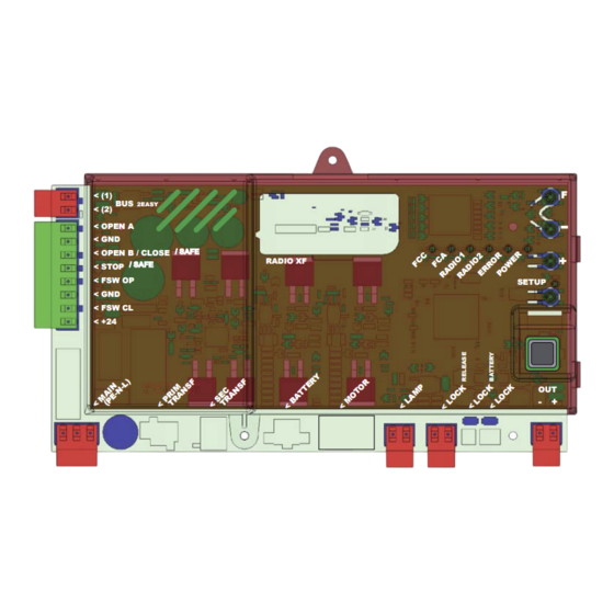
  • Page 1 E721 < (1) 2EASY < (2) < OPEN A < GND < OPEN B / CLOSE / SAFE RADIO XF < STOP / SAFE < FSW OP SETUP < GND < FSW CL < +24...
  • Page 3 8 PROVA DELL’AUTOMAZIONE ......................... 17 9 SEGNALAZIONE ALLARMI ED ERRORI ......................17 9.1 ALLARMI .................................. 17 9.2 ERRORI ................................... 17 10 LOGICHE DI FUNZIONAMENTO ........................18 DICHIARAZIONE CE DI CONFORMITÁ Fabbricante: Indirizzo: Dichiara che: AVVERTENZE 532014 - Rev. D E721...
  • Page 4 E721 1 AVVERTENZE Prima di effettuare qualsiasi tipo di intervento sull’apparecchiatura elettronica (collegamenti, manutenzione) togliere sempre l’alimentazione elettrica. Prevedere a monte dell’impianto un interruttore magnetotermico differenziale con adeguata soglia di intervento. Collegare il cavo di terra all’apposito morsetto. Separare sempre i cavi di alimentazione da quelli di comando e di sicurezza (pulsante, ricevente, fotocellule, ecc.).
  • Page 5 N.C. utilizzando questi ingressi configurati come SAFE, fare riferimento agli schemi indicati in Fig.13 e Fig. 14 N.C. (2) Il carico dell’uscita deve ritenersi già incluso nella corrente max disponibile per gli accessori N.C. 532014 - Rev. D E721...
  • Page 6 I cablaggi indicati in Fig. 2 fanno riferimento agli ingressi della scheda con configurazione di DEFAULT. / SAFE / SAFE 230 V ~ 115 V ~ CONTATTO SBLOCCO MOTORE (Blocca il motore quan- do si aziona la maniglia di sblocco motore) E721 E721 C720 C721 532014 - Rev. D E721...
  • Page 7 Tab. 2 - Descrizione led BUS-2EASY Se non si utilizza alcun accessorio BUS- Acceso 2EASY, lasciare libero il connettore BUS- fisso 2EASY (J12 - fig. 1). Lampeg- giante lento Spento (flash ogni 2,5 sec.) Spento 532014 - Rev. D E721...
  • Page 8 (vedi programmazione di 2° livello e Fig. 6). Utilizzando la sicurezza FAIL-SAFE anche gli ingressi di sicurezza non utilizzati andranno ponticellati col negativo di OUT (vedi Fig. 6). Altre sicurezze 532014 - Rev. D E721...
  • Page 9 FSW CL FSW CL +24V +24V Nel caso non vengano utilizzati dispositivi con contatto N.C. (Altre sicurezze) l’ingresso SAFE divrà essere ponticellato al -OUT con FAIL SAFE attivato o al GND con FAIL SAFE disattivato. 532014 - Rev. D E721...
  • Page 10 Configurando la scheda in modalità SLAVE non verranno visualizzati i parametri LO-PA-Pb-Ph-Op (per funzionamento Master/Slave vedi Par. 7.4) LOGICHE DI FUNZIONAMENTO: ” ” ” ” ” Parametro non visualizzato in modalità SLAVE TEMPO DI PAUSA A: TOTALE Parametro non visualizzato in modalità SLAVE 532014 - Rev. D E721...
  • Page 11 (vedi par. 7.3) VELOCITÀ CHIUSURA: Variando il valore della velocità è consigliabile eseguire un nuovo SETUP (vedi par. 7.3) RALLENTAMENTO IN APERTURA: 5-10-15 RALLENTAMENTO IN CHIUSURA: 5-10-15 VELOCITÀ IN RALLENTAMENTO: STATO DELL’AUTOMAZIONE: ” ” ” ” ” 532014 - Rev. D E721...
  • Page 12 TEMPO DI PRELAMPEGGIO (visibile solo se è stato selezionato un prelampeggio al menù precedente): 1 10 FOTOCELLULE IN CHIUSURA: Parametro non visualizzato in modalità SLAVE FOTOCELLULE IN APERTURA: Parametro non visualizzato in modalità SLAVE FUNZIONE ADMAP: ENCODER: 532014 - Rev. D E721...
  • Page 13 Nel caso si selezioni una logica di funzionamento che prevede l’utilizzo del co- mando di CLOSE (logica ) questa funzione sarà preimpostata a non sarà possibile modificarla. STOP / SICUREZZA COSTA: INVERSIONE PARZIALE: ” BLOCCO MOTORE: 532014 - Rev. D E721...
  • Page 14 A e OPEN B. Per utilizzare diversi sistemi di codifica sullo stesso canale occorre terminare l’appren- dimento di ciascun sistema e successiva- mente ripetere la procedura per l’altro. Non collegare alcun dispositivo radio su apparecchiature configurate come SLAVE. 532014 - Rev. D E721...
  • Page 15 Accertarsi che l’automazione sia libera da ogni ostacolo creato da persone o cose. Questa operazione NON è reversibile. Si cancelleranno tutti i codici dei radiocoman- di memorizzati sia come OPEN A che come OPEN B/CLOSE. 532014 - Rev. D E721...
  • Page 16 (situazione non pregiudicante il funzionamento del cancello) Spento Led ERROR acceso fisso indica errore in corso (situazione che blocca il funziona- 7.2 FUNZIONAMENTO A BATTERIA mento fino alla eliminazione della causa dell’errore) ATTENZIONE 532014 - Rev. D E721...
  • Page 17 APERTURA e il magne- te con il QUADRATO deve essere utilizzato come finecorsa di CHIUSURA (VEDI FIG. 17) In caso di impianto con configurazione MASTER/SLAVE i ma- gneti dei finecorsa dovranno essere in- stallati come in Fig. MASTER/SLAVE 532014 - Rev. D E721...
  • Page 18 MASTER questi valori, forzati precedentemente, vengono mantenuti all’interno della programma- zione. 7.4.1 CABLAGGI MASTER/SLAVE 2 EASY 2 EASY E721 MASTER E721 SLAVE 7.4.2 PROCEDURA DI SETUP MASTER/SLAVE La richiesta di SETUP tramite il lampeggio della sigla sul display può presentarsi sia sulla cen- trale MASTER che sulla centrale SLAVE.
  • Page 19 Alla movimentazione successiva 9 0 9 1 Gli errori sono visualizzati nella stessa direzione, un ostacolo nella solo su E721 configurate come MASTER e stessa posizione provocherà l’arresto del in particolare il e il indicano errori motore. E’ fondamentale configurare presenti sulla centrale SLAVE.
  • Page 20 FSW CL/OP CHIUSO IN APERTURA APERTO IN PAUSA IN CHIUSURA BLOCCATO LOGICA “A1” STATO AUTOMAZIONE OPEN A OPEN B CLOSE STOP FSW OP FSW CL FSW CL/OP CHIUSO IN APERTURA APERTO IN PAUSA IN CHIUSURA BLOCCATO 532014 - Rev. D E721...
  • Page 21 FSW CL/OP CHIUSO IN APERTURA APERTO IN PAUSA IN CHIUSURA BLOCCATO LOGICA “SP” STATO AUTOMAZIONE OPEN A OPEN B CLOSE STOP FSW OP FSW CL FSW CL/OP CHIUSO IN APERTURA APERTO IN PAUSA IN CHIUSURA BLOCCATO 532014 - Rev. D E721...
  • Page 22 FSW CL FSW CL/OP CHIUSO IN APERTURA APERTO IN CHIUSURA BLOCCATO LOGICA “C” COMANDI MANTENUTI IMPULSI STATO AUTOMAZIONE OPEN A CLOSE STOP FSW OP FSW CL FSW CL/OP CHIUSO IN APERTURA APERTO IN CHIUSURA BLOCCATO 532014 - Rev. D E721...
  • Page 23 8 TESTING THE AUTOMATED SYSTEM ......................17 9 ALARM AND ERROR SIGNALS ........................17 9.1 ALARMS ................................... 17 9.2 ERRORS .................................. 17 10 FUNCTION LOGICS ............................ 18 CE DECLARATION OF CONFORMITY Manufacturer: Address: Declares that: WARNINGS 532014 - Rev. D E721...
  • Page 24 E721 1 WARNINGS Before attempting any work on the control board (connections, maintenance), always turn off power. Install, upstream of the system, a differential thermal breaker with adequate tripping threshold. Connect the earth lead to the appropriate terminal. Always separate power cables from control and safety cables (push-button, receiver, photocells, etc.).
  • Page 25 SAFE configured inputs, please refer to the diagrams shown in Fig.13 and Fig. 14 N.C. (2) The output load must be considered as already included in the max. current available for the accessories 532014 - Rev. D E721...
  • Page 26 The wiring shown in Fig. 2 refers to the inputs of the board with DEFAULT configuration. / SAFE / SAFE 230 V ~ 115 V ~ MOTOR RELEASE CONTACT (Locks the motor when the motor release han- dle is operated) E721 E721 C720 C721 532014 - Rev. D E721...
  • Page 27 If no BUS-2EASY accessory is used, leave the Tab. 2 - Description of BUS-2EASY LED BUS-2EASY connector (J12 - fig. 1) free. Fixed ON Slow flasher Off (flash every 2.5 secs) 532014 - Rev. D E721...
  • Page 28 Fig. 6). If the FAIL-SAFE safety device is used, even the unused safety inputs must be connected via a shunt lead to the negative of OUT (see Fig. 6). Other safety devices 532014 - Rev. D E721...
  • Page 29 FSW CL FSW CL +24V +24V In case N.C. contact devices are not used (other safety devices) the SAFE input must be jumpered to -OUT with FAIL SAFE enabled or to GND with FAIL SAFE disabled. 532014 - Rev. D E721...
  • Page 30 Configuring the board in SLAVE mode you will not be able to view the parameters LO-PA-Pb-Ph-Op (for Master/Slave operation see Par. 7.4) FUNCTION LOGICS: “ ” “ ” “ ” ” “ ” Parameter not displayed in SLAVE mode PAUSE TIME A: TOTAL Parameter not displayed in SLAVE mode 532014 - Rev. D E721...
  • Page 31 When the speed value has been changed, it is advisable to perform a new SETUP (see par. 7.3) SLOWING DURING OPENING 5-10-15 SLOWING DURING CLOSING: 5-10-15 SPEED DURING SLOWING: STATUS OF AUTOMATED SYSTEM: “ ” “ ” “ ” “ ” “ ” 532014 - Rev. D E721...
  • Page 32 MAXIMUM TAKE-OFF POWER: PREFLASHING: PREFLASHING TIME (visible only if preflashing is selected in the previous menu): CLOSING PHOTOCELLS: Parameter not displayed in SLAVE mode OPENING PHOTOCELLS: Parameter not displayed in SLAVE mode ADMAP FUNCTION ENCODER: 532014 - Rev. D E721...
  • Page 33 If you select a function logic that involves the use of the CLOSE command (logic ) this function will be preset to and it will not be possible to change it. STOP / EDGE SAFETY DEVICE PARTIAL REVERSE: ” MOTOR LOCK: 532014 - Rev. D E721...
  • Page 34 A and OPEN B. To use the different coding systems on the same channel, finish the learning process for each system and then repeat the pro- cedure for another.. Do not connect any radio devices on SLAVE-configured equipment 532014 - Rev. D E721...
  • Page 35 Ensure the automated This operation is NOT reversible. All the codes device is free of any obstacle by people of the radiocontrols stored as OPEN A and or things. as OPEN B/CLOSE will be deleted. 532014 - Rev. D E721...
  • Page 36 (situation does not impair gate operation) ERROR LED on with a fixed light indicates an error in progress (situation that locks operation until the cause of the error has 7.2 BATTERY OPERATION been removed) ATTENTION “ ” 532014 - Rev. D E721...
  • Page 37 SQUARE must be used as a CLOSING limit switch. (SEE FIG. 17) When using a system with MASTER/SLAVE configuration, the limit switch magnets must be installed as shown in Fig. 18. MASTER/SLAVE 532014 - Rev. D E721...
  • Page 38 7.4.1 MASTER / SLAVE WIRING 2 EASY 2 EASY E721 MASTER E721 SLAVE 7.4.2 MASTER/SLAVE SETUP PROCEDURE The SETUP request signalled by the flashing on the display can occur both on the MASTER unit and on the SLAVE unit.
  • Page 39 It is essential to correctly Errors are displayed configure this parameter to adjust the only on E721 configured as MASTER and correct sensitivity of the “virtual” encoder in particular indicate errors with respect to obstacles during motion.
  • Page 40 DURING OPENING OPEN IN PAUSE DURING CLOSING LOCKED LOGIC "A1" PULSES OPEN A OPEN B CLOSE STOP FSW OP FSW CL FSW CL/OP STATUS OF AUTOMATED SYSTEM CLOSED DURING OPENING OPEN IN PAUSE DURING CLOSING LOCKED 532014 - Rev. D E721...
  • Page 41 DURING OPENING OPEN IN PAUSE DURING CLOSING LOCKED LOGIC "SP" PULSES OPEN A OPEN B CLOSE STOP FSW OP FSW CL FSW CL/OP STATUS OF AUTOMATED SYSTEM CLOSED DURING OPENING OPEN IN PAUSE DURING CLOSING LOCKED 532014 - Rev. D E721...
  • Page 42 STATUS OF AUTOMATED SYSTEM CLOSED DURING OPENING OPEN DURING CLOSING LOCKED LOGIC "C" COMMANDS MAINTAINED PULSES OPEN A CLOSE STOP FSW OP FSW CL FSW CL/OP STATUS OF AUTOMATED SYSTEM CLOSED DURING OPENING OPEN DURING CLOSING LOCKED 532014 - Rev. D E721...
  • Page 43 8 TEST DE L'AUTOMATISME ........................... 17 9 SIGNALISATION D'ALARMES ET D'ANOMALIES ....................17 9.1 ALARMES ................................17 9.2 ERREURS .................................. 17 10 LOGIQUES DE FONCTIONNEMENT ....................... 18 DÉCLARATION CE DE CONFORMITÉ Fabricant : Adresse : Déclare que : AVERTISSEMENTS 532014 - Rev. D E721...
  • Page 44 E721 1 AVERTISSEMENTS Avant d'effectuer un type quelconque d'intervention sur l'appareil électronique (branchements, entretien), couper toujours l'alimentation électrique. En amont de l'installation, prévoir un interrupteur magnétothermique différentiel avec un seuil d'intervention adapté. Brancher le câble de terre à la borne correspondante.
  • Page 45 SAFE, se référer aux schémas indiqués dans les figures Fig.13 et Fig. 14. N.F. (2) L'alimentation en sortie doit déjà être comprise dans le courant maximum disponible pour les accessoires 532014 - Rev. D E721...
  • Page 46 Les câblages indiqués dans la Fig. 2 se réfèrent aux entrées de la carte avec une configuration par DÉFAUT. / SAFE / SAFE 230 V ~ 115 V ~ CONTACT DEVERROUILLAGE DE MOTEUR (Bloque le moteur quand la poignée de déver- rouillage moteur est actionnée) E721 E721 C720 C721 532014 - Rev. D E721...
  • Page 47 Il faut s'assurer qu'il n'y ait pas deux ou Allumé fixe plusieurs paires de photocellules avec la même adresse. Clignotant Si l'on n'utilise aucun accessoire BUS-2EASY, lent laisser libre le connecteur BUS-2EASY (J12 - Éteint Fig. 1). (clignotement toutes les 2,5 sec.) Éteint 532014 - Rev. D E721...
  • Page 48 (voir pro- grammation de 2 niveau et Fig. 6). ème En utilisant la sécurité FAIL-SAFE, les entrées de sécurité non utilisées devront également être shuntées avec le négatif d'OUT (voir Fig. 6). Autres sécurités 532014 - Rev. D E721...
  • Page 49 FSW OP FSW CL FSW CL +24V +24V Si l’on utilise les dispositifs avec un contact N.F. (Autres sécurités), ponter l’entrée SAFE au négatif -OUT avec FAIL SAFE activé ou à GND avec FAIL SAFE désactivé. 532014 - Rev. D E721...
  • Page 50 En configurant la carte en modalité SLAVE, les paramètres sont pas affichés (pour le fonctionnement Master/Slave, voir Par. 7.4) LOGIQUES DE FONCTIONNEMENT : Paramètre non affiché en modalité SLAVE TEMPS DE PAUSE A : TOTALE Paramètre non affiché en modalité SLAVE 532014 - Rev. D E721...
  • Page 51 En modifiant la valeur de la vitesse, il est conseillé d'effectuer un nouveau SETUP (voir par. 7.3) RALENTISSEMENT EN OUVERTURE : 5-10-15 RALENTISSEMENT EN FERMETURE : 5-10-15 VITESSE EN RALENTISSEMENT : ÉTAT DE L'AUTOMATISME : 532014 - Rev. D E721...
  • Page 52 TEMPS DE PRÉ-CLIGNOTEMENT (visible uniquement si un pré-clignotement a été sélectionné dans le menu précédent) : 1 10 PHOTOCELLULES EN FERMETURE : Paramètre non affiché en modalité SLAVE PHOTOCELLULES EN OUVERTURE : Paramètre non affiché en modalité SLAVE FONCTION ADMAP : ENCODER : 532014 - Rev. D E721...
  • Page 53 Si l'on sélectionne une logique de fonctionnement qui prévoit l'utilisation de la commande de CLOSE (logique ), cette fonction sera préréglée sur et il ne sera pas possible de la modifier. STOP / SÉCURITÉ BORD : INVERSION PARTIELLE : BLOCAGE MOTEUR : 532014 - Rev. D E721...
  • Page 54 Pour utiliser différents systèmes de codage sur le même canal, il faut terminer l'appren- tissage de chaque système et répéter suc- cessivement la procédure pour l'autre.. Ne connecter aucun dispositif radio sur des armoires configurées comme SLAVE. 532014 - Rev. D E721...
  • Page 55 L’automatisme effectuera une ouverture. codes des radiocommandes mémorisées se- Il faut s'assurer que l'automatisme ne pré- ront effacés, tant comme OPEN A que comme sente aucun obstacle créé par des personnes OPEN B/CLOSE. ou des biens. 532014 - Rev. D E721...
  • Page 56 (situation ne nuisant pas au bon Éteint fonctionnement du portail) Led ERROR allumé fixe indique l'erreur en cours (situation qui bloque le fonctionne- ment jusqu'à l'élimination de la cause de 7.2 FONCTIONNEMENT À BATTERIE l'erreur) ATTENTION 532014 - Rev. D E721...
  • Page 57 En cas d’installation e n c o n f i g u r a t i o n MA STER/SL AVE, les aimants de fin de course devront être installés d’après la Fig. 18. MASTER/SLAVE 532014 - Rev. D E721...
  • Page 58 MASTER, ces valeurs qui avaient été forcées sont maintenues à l’intérieur de la programmation. 7.4.1 CÂBLAGES MASTER-SLAVE 2 EASY 2 EASY E721 MASTER E721 SLAVE 7.4.2 PROCÉDURE DE SETUP MASTER-SLAVE La demande de SETUP par l’intermédiaire du clignotement du sigle sur l’afficheur peut s’afficher sur la centrale MASTER et sur la centrale SLAVE.
  • Page 59 E721 configuré comme I l e s t f o n d a m e n t a l d e c o n f i g u r e r MASTER et en particulier les codes correctement ce paramètre pour régler...
  • Page 60 OUVERT EN PAUSE EN FERMETURE BLOQUE LOGIQUE « A1 » IMPULSIONS ETAT DE L' A UTOMATISME OPEN A OPEN B CLOSE STOP FSW OP FSW CL FSW CL/OP FERME EN OUVERTURE OUVERT EN PAUSE EN FERMETURE BLOQUE 532014 - Rev. D E721...
  • Page 61 OUVERT EN PAUSE EN FERMETURE BLOQUE LOGIQUE « SP » IMPULSIONS ETAT DE L' A UTOMATISME OPEN A OPEN B CLOSE STOP FSW OP FSW CL FSW CL/OP FERME EN OUVERTURE OUVERT EN PAUSE EN FERMETURE BLOQUE 532014 - Rev. D E721...
  • Page 62 EN OUVERTURE OUVERT EN FERMETURE BLOQUE LOGIQUE « C » COMMANDES MAINTENUES IMPULSIONS ETAT DE L' A UTOMATISME OPEN A CLOSE STOP FSW OP FSW CL FSW CL/OP FERME EN OUVERTURE OUVERT EN FERMETURE BLOQUE 532014 - Rev. D E721...
  • Page 63 2006/95/EG Niederspannungsrichtlinie 2004/10 /EG ichtlinie zur elektromagnetischen Verträglichkeit Anmerkung: Dieses Produkt wurde in einer typisch homogenen Konfiguration getestet (sämtliche Bauprodukte der Firma FAAC S.p.A.). Bologna, den 01-12-2011 Der Geschäftsführer A. Marcellan HINWEISE Achtung! Um die Personensicherheit zu gewährleisten, sollte die Anleitung aufmerksam befolgt werden.
  • Page 64 E721 1 HINWEISE Vor dem Ausführen jeglicher Art von Eingriffen am elektronischen Gerät (Anschlüsse, Instandhaltung) muss immer die Stromzufuhr abgeschaltet werden. Vor der Anlage sollte ein Differential-Wärmeschutzschalter mit entsprechender Auslöseschwelle vorgesehen werden. Das Erdungskabel an die entsprechende Klemme anschließen. Die Versorgungskabel immer von den Kabeln für die Steuerung und die Sicherheitsvorrichtungen (Taste, Empfänger, Fotozellen...
  • Page 65 (1) Die elektrische Ausgangsbelastung muss Vorrichtung mit ARBEITSKONTAKT, bereits im max. für die Zubehörgeräte ver- durch welche die Bewegung fügbaren strom berücksichtigt werden während des Schließens des Tors umgekehrt wird +24 V Positiv Versorgung Zubehörgeräte 532014 - Rev. D E721...
  • Page 66 230 V ~ 115 V ~ KONTAKT MOTORENTRIEGELUNG (Blockiert den Motor, wenn der Griff für die Entriegelung des Motors betätigt wird) Abb. 2 Fig. 2 E721 E721 C720 C721 Abb. Fig. Fotozellen für den SCHLIESS-Vorgang Fotozellen für den FFNUNGS-Vorgang Fotozellen für den FFNUNGS- und SCHLIESS-Vorgang Abb.
  • Page 67 Fotozelle belegt. Blinkt Mindestens eine angesteuerte Fotozelle belegt langsam bzw. nicht ausgerichtet. Ausgeschaltet (blinkt alle Kurzschluss BUS-2EAS -Leitung. 2,5 sec) - BUS-2EAS -Leitung deaktiviert (keine Versorgung) Ausgeschaltet - Batteriebetrieb - Steuergerät als SLAVE programmiert 532014 - Rev. D E721...
  • Page 68 Wenn die Sicherheitsvorrichtung FAIL-SAFE verwendet wird, und eines Paars beim ffnungs-/Schließvorgang müssen auch die nicht benutzten Sicherheitseingänge mit dem Negativ von OUT (siehe Abb. 6) überbrückt werden. Anschluss eines Fotozellenpaars beim ffnungsvorgang Andere Sicher- heitsvorrichtungen Abb. 7 Abb. 10 532014 - Rev. D E721...
  • Page 69 FSW OP FSW OP FSW CL FSW CL +24V Abb. 14 +24V Wenn Vorrichtungen mit Öffnerkontakt (andere Sicherheitseinrichtungen) eingesetzt werden, muss der SAFE-Eingang bei aktivierter FAILSAFE-Funktion an -OUT und bei deaktivierter FAILSAFE-Funktion an GND überbrückt werden. 532014 - Rev. D E721...
  • Page 70 Punkt getrennt sind) und die Zeit wird mit Schritten von jeweils 10 Sekunden bis zum maximalen ert von Minuten eingestellt. Z.B.: enn das Display anzeigt, beträgt die Pausenzeit 2 min und 50 sec. Im SLAVE-Modus nicht angezeigter Parameter 532014 - Rev. D E721...
  • Page 71 = Stillstand, dann FFNEN“ im Gange = Stillstand, dann SCHLIESSEN“ = Vorblinken, dann FFNEN“ = In PAUSE“ = Vorblinken, dann SCHLIESSEN“ = In ffnungsphase = GE FFNET bei Teilöffnung = In Schließphase = In PAUSE bei Teilöffnung 532014 - Rev. D E721...
  • Page 72 Die Empfindlichkeit des virtuellen“ Gebers muss eingestellt werden, wobei der Zeitraum, den die Karte wartet, bevor die Umkehr der Bewegung veranlasst wird, von einem Minimum von bis zu einem Maximum von sec in Schritten von einer Sekunde reichen kann. = höchste Empfindlichkeit = niedrigste Empfindlichkeit 532014 - Rev. D E721...
  • Page 73 Schließposition gefahren. MOTORVERRIEGELUNG: Es ist möglich, den Einsatz der Motorverriegelung während des Batteriebetriebs auszuwählen: = die Motorverriegelung funktioniert auch während des Batteriebetriebs regelmäßig weiter = im Batteriebetrieb bleibt die Motorverriegelung stets geöffnet 532014 - Rev. D E721...
  • Page 74 6. Um andere Codes hinzuzufügen, müssen die muss zuerst der Lernvorgang für ein System Arbeitsschritte ab Punkt 1 wiederholt werden. abgeschlossen und derselbe Arbeitsschritt dann für das nächste System angewandt werden. Keine Funkeinrichtung an als SLAVE konfigurierte Geräte anschließen. 532014 - Rev. D E721...
  • Page 75 Die Automation öffnet sich. Sicherstellen, dass die Automation frei von Hindernissen Dieser Vorgang kann NICHT rückgängig (Personen bzw. Gegenstände) ist. gemacht werden. Es werden sämtliche sowohl als OPEN A als auch als OPEN B/CLOSE gespeicherten Codes der Funksteuerungen gelöscht. 532014 - Rev. D E721...
  • Page 76 Taste + auf der Steuerkarte drücken. Nach diesem kurzen Tastendruck wird der Zustand der Automation für 2 Sekunden am Display LCD1 angezeigt, das danach wieder abgeschaltet wird. ährend einer normalen Bewegung arbeiten dagegen alle Diagnose-LED und LED zur Statusanzeige des Displays wieder entsprechend dem Zustand der Automation (siehe Abb. 16). 532014 - Rev. D E721...
  • Page 77 QUADRATISCHEN ENDE als Endschalter für den SCHLIESSVORGANG benutzt werden. (SIEHE ABB. 17) Bei Anlagen mit MASTER- SLAVE-Konfiguration müssen die Magneten der Endschalter gemäß den Anweisungen in Abb. 18 eingebaut werden. Abb, 17 MASTER/SLAVE Abb. 18 532014 - Rev. D E721...
  • Page 78 7.4 MASTER-SLAVE-KONFIGURATION Muss eine Anlage mit gegenläufigen Torflügeln realisiert werden, die zum ffnen und Schließen der Zufahrt gleichzeitig zu betätigen sind, besteht die Möglichkeit, zwei E721-Geräte im Master-Slave-Modus anzuschließen und einzurichten. Das MASTE -Gerät (festgelegter ert für den Parameter der ersten Programmierebene: ) muss alle für...
  • Page 79 Die Fehlercodes werden nur ein Hindernis an derselben Position die an als MASTER konfigurierten E721-Geräten Stillsetzung des Motors. Die korrekte angezeigt; insbesondere verweisen die Codes E i n s t e l l u n g d i e s e s Pa r a m e t e r s z u r auf Fehler am SLAVE-Steuergerät.
  • Page 80 Auswirkung keine Auswirkung keine Auswirkung BLOCKIERT schließt das Tor schließt das Tor schließt das Tor (OPEN/CLOSE unterdrückt) (OPEN unterdrückt) (CLOSE unterdrückt) (OPEN/CLOSE unterdrückt) ährend des Teilöffnungszyklus wird das Tor durch einen OPEN-A-Impuls vollständig geöffnet. 532014 - Rev. D E721...
  • Page 81 (OPEN unterdrückt) (CLOSE unterdrückt) (OPEN/CLOSE unterdrückt) schl i e ßt das Tor i m mer schl i e ßt das Tor i m mer ährend des Teilöffnungszyklus wird das Tor durch einen OPEN-A-Impuls vollständig geöffnet. 532014 - Rev. D E721...
  • Page 82 ährend des Teilöffnungszyklus wird das Tor durch einen OPEN-A-Impuls vollständig geöffnet. (2) Beim Einschalten werden von der Karte die Eingänge überprüft, und wenn ein OPEN-A- bzw. ein OPEN-B-Befehl aktiv ist, öffnen sich der Flügel bzw. das Tor, ansonsten werden sie geschlossen. 532014 - Rev. D E721...
  • Page 83 2006/95/CE Directiva Baja Tensi n 2004/108/CE Directiva Compatibilidad Electromagn tica Nota adicional: Este producto se ha sometido a pruebas en una configuraci n t pica homog nea (todos los productos est n fabricados por FAAC S.p.A.). Bolonia, 01-12-2011 El Administrador Delegado A. Marcellan ADVERTENCIAS Atenci n! Para la seguridad de las personas es sumamente importante seguir atentamente estas instrucciones.
  • Page 84 E721 1 ADVERTENCIAS Desconecte la alimentación eléctrica antes de realizar cualquier intervención en la instalación electrónica (conexiones, mantenimiento). Coloque encima del equipo un interruptor magnetotérmico diferencial con un umbral de inter- vención adecuado. Conecte el cable de tierra al borne correspondiente.
  • Page 85 (2) La carga de la salida debe considerarse si n del movimiento duran- ya incluida en la corriente máx. disponible te el cierre de la cancela para los accesorios +24 V Positivo alimentaci n accesorios 532014 - Rev. D E721...
  • Page 86 DE DESBLOQUEO DEL MOTOR (Bloquea el motor cuan- do se acciona la mani- lla de desbloqueo del motor) Fig. 2 E721 E721 C720 C721 Fig. Fotoc lulas con intervenci n en CIE Fotoc lulas con intervenci n en APE TU A Fotoc lulas con intervenci n en APE TU A y CIE Fig.
  • Page 87 Apagado (luz cada L nea BUS-2EAS en cortocircuito 2,5 s) -L nea BUS-2EAS desactivada (no sumini- stra alimentaci n) Apagado - Funcionamiento con bater a. - Central programada como SLAVE 532014 - Rev. D E721...
  • Page 88 OUT (véase Fig. 6). Conexión de un par de fotoc lulas en apertura Otros dispositivos de seguridad Fig. 7 Fig. 10 532014 - Rev. D E721...
  • Page 89 Fig. 14 +24V Si no se utilizan dispositivos con contacto N.C. (Otros dispositivos de seguridad) la entrada SAFE deberá puentearse con el -OUT con FAIL SAFE activado, o con el GND con FAIL SAFE desactivado. 532014 - Rev. D E721...
  • Page 90 10 segundos hasta un valor m ximo de minutos. EJ.: si la pantalla indica , el tiempo de pausa corresponde a 2 minutos y 50 segundos Parámetro no visualizado en modo SLAVE 532014 - Rev. D E721...
  • Page 91 = Parpadeo previo, despu s “AB I ” = En “PAUSA” = Parpadeo previo, despu s “CE A ” = En fase de apertura = ABIE TO en Apertura parcial = En fase de cierre = En PAUSA Apertura parcial 532014 - Rev. D E721...
  • Page 92 Es necesario regular la sensibilidad del encoder “virtual“ modificando el tiempo que la tarjeta espera antes de accionar la inversión del movimiento desde un m nimo de segundos a un m ximo de segundos en pasos de un segundo. = m xima sensibilidad = m nima sensibilidad 532014 - Rev. D E721...
  • Page 93 Se puede seleccionar el uso del bloque motor durante el funcionamiento con bater a: = el bloque motor sigue funcionando normalmente durante el funcionamiento con bater a. = cuando se pasa al funcionamiento con bater a el bloque motor permanece siempre abierto. 532014 - Rev. D E721...
  • Page 94 6. Para a adir otros códigos diferentes al que acaba de finalizar el aprendizaje de cada sistema y, a memorizar repita el procedimiento desde el punto 1. continuación, repetir el procedimiento para el otro. No conecte ningún dispositivo radio en equipos configurados como SLAVE. 532014 - Rev. D E721...
  • Page 95 Asegúrese de que en el automatismo no Esta operación NO es reversible. Se elimina- haya ningún obstáculo creado por perso- rán todos los códigos de los radiomandos nas u objetos. memorizados como OPEN A o como OPEN B/CLOSE. 532014 - Rev. D E721...
  • Page 96 Sin embargo, durante un movimiento normal, todos los diodos de diagnóstico y las se alizaciones del display vuelven a ser coherentes con el estado del automatismo (v ase Fig. 16). 532014 - Rev. D E721...
  • Page 97 S i e l e q u i p o e s t á configurado MASTER/ SLAVE, los imanes de los finales de carrera deben estar instalados como se muestra en la Fig. 18. Fig. 17 MASTER/SLAVE Fig. 18 532014 - Rev. D E721...
  • Page 98 Si fuera necesario realizar un equipo con hojas contrapuestas que se han de accionar simult neamente para la apertura y el cierre de la v a, se pueden conectar y configurar dos equipos E721 en modo Master/Slave. El equipo MASTE (par metro del primer nivel de programación configurado como...
  • Page 99 9 0 9 1 Los errores sólo aparecen la parada del motor. Es fundamental en E721 configuradas como MASTER y en configurar correctamente este parámetro especial el y el indican errores para ajustar la correcta sensibilidad del presentes en la central SLAVE.
  • Page 100 BLOQUEADO cierra la cancela cierra la cancela cierra la cancela (OPEN/CLOSE inhibidos) (OPEN inhibido) (CLOSE inhibido) (OPEN/CLOSE inhibidos) (1) Durante el ciclo de apertura parcial, un impulso de OPEN A provoca la apertura total 532014 - Rev. D E721...
  • Page 101 (OPEN/CLOSE i n hi b i d os) de STOP ci e rra si e mpre de STOP ci e rra si e mpre (1) Durante el ciclo de apertura parcial, un impulso de OPEN A provoca la apertura total 532014 - Rev. D E721...
  • Page 102 (1) Durante el ciclo de apertura parcial, un impulso de OPEN A provoca la apertura total (2) Cuando se enciende, la tarjeta comprueba las entradas y si un accionamiento de OPEN A o B est activo abre la hoja o la cancela, de lo contrario, cierra. 532014 - Rev. D E721...
  • Page 103 CE-VERKLARING VAN OVEREENSTEMMING Fabrikant: FAAC S.p.A. Adres: Via Calari, 10 - 40069 Zola Predosa BOLOGNA - ITALI verklaart dat: De elektronische apparatuur E721 in overeenstemming is met de belangrijkste veiligheidseisen van de volgende EEG-richtlijnen: 2006/95/EG Laagspanningsrichtlijn 2004/108/EG ichtlijn Elektromagnetische compatibiliteit...
  • Page 104 E721 1 WAARSCHUWINGEN Alvorens werkzaamheden aan de elektronische apparatuur te verrichten (aansluitingen, onderhoud) moet altijd eerst de elektrische voeding worden weggenomen. Breng bovenstrooms van het systeem een thermomagnetische differentieelschakelaar aan met een juiste inschakellimiet. Sluit de aardleiding op de betreffende klem aan.
  • Page 105 Inrichting met NG-contact dat zorgt voor de omkering van de beweging tijdens het sluiten van de poort +24V Positieve voor voeding accessoires 532014 - Rev. D E721...
  • Page 106 115 V ~ CONTACT MOTORONTGRENDELING (Blokkeert de motor wanneer de hendel van de motorontgrendeling wordt bewogen) Fig. 2 E721 E721 C720 C721 Fig. Fotocellen voor interventie tijdens SLUITING Fotocellen voor interventie tijdens OPENING Fotocellen voor interventie tijdens OPENING en SLUITING Fig.
  • Page 107 -Lijn BUS-2EAS gedeactiveerd (geeft geen voeding) erking op batterijen. - B e s t u r i n g s e e n h e i d a l s S L A V E geprogrammeerd 532014 - Rev. D E721...
  • Page 108 Wanneer de FAIL-SAFE beveiliging wordt gebruikt, moeten ook de niet-gebruikte veiligheidsingangen paar bij opening/sluiting worden verbonden met de negatieve pool van OUT (zie fig. 6). Aansluiting van n paar fotocellen bij opening Overige beveiligingen Fig. 7 Fig. 10 532014 - Rev. D E721...
  • Page 109 FSW CL FSW CL +24V Fig. 14 +24V Als geen inrichtingen met een NG-contact (andere veiligheidsinrichtingen) worden gebruikt, moet de SAFE-ingang met -OUT worden doorverbonden als FAIL-SAFE is geactiveerd, of met GND als FAIL-SAFE is gedeactiveerd. 532014 - Rev. D E721...
  • Page 110 Vervolgens verandert de weergave in minuten en tienden van seconden (gescheiden door een punt) en is de tijd instelbaar in stappen van 10 seconden, tot de maximumwaarde van minuten. Bijv.: als het scherm aangeeft, correspondeert de pauzetijd met 2 min. en 50 sec. Parameter niet weergegeven in SLAVE-modus 532014 - Rev. D E721...
  • Page 111 = Gestopt daarna “OPENEN” = Voorknipperen daarna “OPENEN” = Gestopt daarna “SLUITEN” = Voorknipperen daarna “SLUITEN” = In “PAUZE” = OPEN bij Gedeeltelijke opening = Gaat open = In PAUZE bij Gedeeltelijke opening = Gaat dicht 532014 - Rev. D E721...
  • Page 112 De gevoeligheid van de virtuele encoder moet worden ingesteld door de wachttijd, voordat de kaart het commando geeft tot omkering van de beweging, in te stellen van minimaal sec tot maximaal sec in stappen van een seconde. = maximale gevoeligheid = minimale gevoeligheid 532014 - Rev. D E721...
  • Page 113 Het is mogelijk om het gebruik van de motorblokkering te selecteren tijdens de werking op accu: = de motorblokkering blijft gewoon functioneren ook tijdens de werking op accu = wanneer wordt overgegaan op de werking op accu blijft de motorblokkering altijd open. 532014 - Rev. D E721...
  • Page 114 1 worden herhaald. beëindigd en moet vervolgens de procedure voor het andere worden herhaald. Sluit geen enkele radiovoorziening op de als SLAVE geconfigureerde apparatuur aan. 532014 - Rev. D E721...
  • Page 115 Deze handeling kan NIET ongedaan worden kels in de vorm van personen of voorwer- gemaakt. Alle codes van de radiobesturin- pen. gen die zowel als OPEN A of OPEN B/CLOSE in het geheugen zijn opgeslagen, zullen worden gewist. 532014 - Rev. D E721...
  • Page 116 Gedurende de normale beweging werken alle diagnoseleds en de signaleringen van de status van het display daarentegen weer conform de daadwerkelijke toestand van het automatisch systeem (zie Fig. 16). 532014 - Rev. D E721...
  • Page 117 ï n s t a l l e e r d z o a l s aangegeven in Fig. 18. Fig. 17 MASTER/SLAVE Fig. 18 532014 - Rev. D E721...
  • Page 118 7.4 CONFIGURATIES MASTER / SLAVE Als een installatie moet worden vervaardigd met tegenoverstaande vleugels die tegelijkertijd moeten worden ingeschakeld voor het openen en sluiten van de doorgang, moeten de twee apparaten E721 in de modus Master-/ Slave worden aangesloten en geconfigureerd.
  • Page 119 MASTER geconfigureerde motor gestopt. Het is fundamenteel deze E721’s; 9 geven foutmeldingen parameter correct te configureren om aan op de SLAVE-besturingseenheid. Als deze de juiste gevoeligheid van de “virtuele”...
  • Page 120 GEBLOKKEERD sluit de poort sluit de poort sluit de poort (OPEN/CLOSE onderdrukt) (OPEN onderdrukt) (CLOSE onderdrukt) (OPEN/CLOSE onderdrukt) (1) Tijdens de gedeeltelijke openingscyclus zorgt een impuls OPEN A voor de totale opening 532014 - Rev. D E721...
  • Page 121 (OPEN/CLOSE onderdrukt) (OPEN onderdrukt) (CLOSE onderdrukt) (OPEN/CLOSE onderdrukt) na STOP al t i j d na STOP al t i j d (1) Tijdens de gedeeltelijke openingscyclus zorgt een impuls OPEN A voor de totale opening 532014 - Rev. D E721...
  • Page 122 (1) Tijdens de gedeeltelijke openingscyclus zorgt een impuls OPEN A voor de totale opening (2) Bij inschakeling controleert de kaart de ingangen en als een commando OPEN A of B actief is, wordt de vleugel of poort geopend, of anders gesloten. 532014 - Rev. D E721...
  • Page 124 +33 4 72218700 tel. +1 904 4488952 tel. +971 42146733 www.faac.fr www.faacusa.com www.faac.ae FAAC FRANCE - AGENCE PARIS FAAC INTERNATIONAL INC Massy - Paris, France Fullerton, California - U.S.A. tel. +33 1 69191620 tel. +1 714 446 9800 www.faac.fr www.faacusa.com...